
Damage Repair and Distressing
In general, the goal of visual effects compositing is to seamlessly integrate elements such as live-action plates, 3D animation, digital matte paintings, and so on. Part of this task requires the removal or integration of artifacts that naturally occur when motion picture film, analog video, or digital video is captured. Grain and noise are common artifacts that you can remove within After Effects. Conversely, you have the option to add noise or grain to elements that lack it, such as 3D renders. Randomly appearing artifacts, which include scratches and dust, require more complex techniques for removal or addition. The After Effects set of paint tools offers a means to remove random artifacts and any unwanted elements through the “paint fix” process (Figure 9.1). Another variation of distress involves the addition of distortion effects.
This chapter includes the following critical information:
• Adding noise, grain, and similar film and video artifacts
• Removing noise and grain
• Repairing and altering footage with paint tools
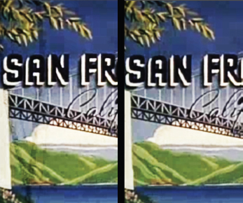
FIG 9.1 Left: Damaged motion picture film footage with two large scratches at the left of frame. Right: Same footage after paint fixes are applied. This process is demonstrated in the “Removing Film Damage” mini-tutorial later in this chapter.
Working with Noise, Grain, and Compression Blocks
Motion picture film captures images with a celluloid or plastic base coated with gelatin containing microscopic, light-sensitive silver halide crystals. The presence of the crystals creates the appearance of film grain (Figure 9.2). The grain varies with each frame and therefore appears to be in constant motion. The size, color, and contrast of the grain varies with each specific film stock.
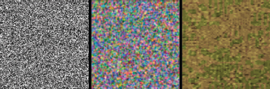
FIG 9.2 Left to right: Close-ups of film grain, video noise, and video compression blocks as they might appear over a gray field.
In comparison, video noise occurs when light photons randomly strike a sensor in a low-light scenario or when random electrical signals are present in a system. Video noise appears as one-pixel, random variations in color or brightness (Figure 9.2). Video static occurs when the only information present is noise (hence, you see static on a television when there is no reception).
Video compression blocks, which appear as irregularly formed rectangular shapes, are created by compression algorithms in order to reduce file size (Figure 9.2). Compression blocks and noise may appear simultaneously in a video sequence. Although professional digital cameras suffer less from noise and compression blocks, all digital video carries these artifacts to some degree.
After Effects provides an Effects > Noise & Grain menu. You can use the Remove Grain effect, available in this menu, to remove noise or grain. You can follow these basic steps:
1. When you apply the Remove Grain effect, the result is displayed in a white preview box (Figure 9.3). You can move the preview box to different areas of the frame by LMB-dragging the box center. You can alter the box size by changing the Width and Height values in the Preview Region section. Due to the calculation-intensive grain removal process, it’s generally better to fine-tune the effect while previewing a small area.
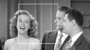
FIG 9.3 Close-up of a grainy motion picture film clip. The Remove Grain effect reduces the grain within its white preview box. The footage is included as Grainy.##.png in the ProjectFiles PlatesNoiseGrainScratchesGrainy directory.
2. Adjust the aggressiveness of the effect by raising or lowering the Noise Reduction property in the Noise Reduction Settings section. The goal is to remove the noise and grain without overly softening the resulting image. To further adjust the result, you can change the Passes value, which sets the number of iterative reduction passes. Lower Passes property values tend to create a blotchier result. You also have the option to adjust the removal aggressiveness per channel through the Channel Noise Reduction subsection. Color film and video often creates different degrees of noise in the red, green, and blue channels. You can view a color channel at any time by using the Show Channel button menu in the view panel.
3. You can resharpen the result by raising the Amount value in the Unsharp Mask section. The unsharp mask process increases the contrast around edges. The extent of the high-contrast area is set by the Radius property. Use this section with caution. Excessive sharpening may reveal or exaggerate additional artifacts, such as compression blocks, dirt, or other damage.
4. When you are satisfied with the settings, change the Viewing Mode menu from Preview to Final Output. Test the settings at different frames along the timeline.
The clip used in this section is taken from Soundie: Reg Kehoe and his Marimba Queens, a short film from the Prelinger Archives, made available via a Creative Commons Public Domain license. For more information, visit www.archive.org/details/prelinger.
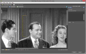
There are a number of third-party plug-ins that tackle noise removal. For example, the Neat Video Reduce Noise plug-in offers advanced removal techniques. The following tutorial describes its application.
Neat Video mini-tutorial
To apply Neat Video Reduce Noise, follow these basic steps:
1. Select the layer that contains the noise or grain and choose Effect > Neat Video > Reduce Noise.
2. In the Effect Controls tab, click on the Options link at the top of the Reduce Noise properties section. A separate window opens.
3. The first step to the removal process is the identification of a noise pattern within a region of the frame that includes little variation (e.g. en empty sky or blank wall). The plug-in identifies this area automatically if you click the Auto Profile button at the top left. A blue square appears over the identified region. If the square is less than 128x128 pixels in size, a warning box opens; despite this, you can choose to build a noise profile by clicking the Yes button. The larger the noise pattern region, the greater the success of the plug-in. However, the plug-in often works with small regions.
4. Alternatively, you can LMB-drag a region box in the plug-in window viewer to manually identify a noise pattern region. The box appears yellow (Figure 9.4). To create the noise profile at that point, click the Auto Profile button. With the creation of the profile, the Noise Filter Settings tab becomes available. Switch to that tab.
5. The Noise Filter Settings tab allows you to fine-tune the aggressiveness of the noise removal. To adjust the removal based on luminance (brightness), adjust the Luminance slider at the right. To adjust the removal based on color values, adjust the Chrominance slider. The result is visible in the plug-in window viewer. You can resharpen the edges within the frame by adjusting the Amount slider in the Sharpening section. This sharpen varies from the After Effects Remove Grain effect in that it doesn’t use an unsharp filter, which tends to create heavy contrast around edge. Nonetheless, high Amount slider values may reveal compression block edges or create diagonal striations.
6. When you’re satisfied with the results, click the Apply button at the bottom right. The window closes and the removal is applied to the timeline. For more information on the Neat Video Reduce Noise plug-in, visit www.neatvideo.com.
To better match a particular piece of footage, it may be necessary to add noise or grain to a layer. For example, you may choose to add noise to a 3D render to better integrate it with live-action footage. There are two ways to approach this: add generic noise/grain or replicate noise/grain from a different layer.
To add a generic grain to a layer, you can apply the Add Grain effect (in the Effect > Noise & Grain menu). The effect is designed to replicate film grain, which tends to appear larger and more irregular than video noise. However, you can reduce the grain size to make the result more video-like. The effect includes the following properties and property sections:
Viewing Mode This menu allows you to preview a small area and functions in the same way as it does for the Remove Grain effect (Figure 9.5).
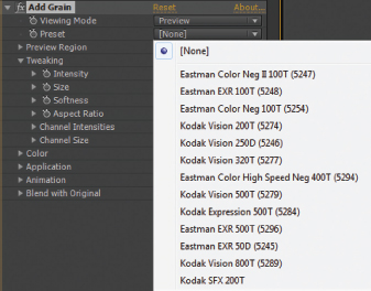
FIG 9.5 The Add Grain effect and its list of available Presets that emulate specific film stocks. Note that the effect shares many properties with the Remove Grain effect.
Preset This menu offers a number of presets that match specific motion picture film stocks. Although this menu is optional, it provides a quick way to create a wide range of looks.
Tweaking and Application These sections set the intensity (brightness), grain size, grain softness, and contrast between the shadows, midtone, and highlight regions.
Color This section allows you to create monochromatic (grayscale) grains or tint them with a single color. Older film and video technologies that produce black-and-white images create monochromatic noise and grain while newer color technologies create color noise and grain.
Animation By default, grain created with the Add Grain effect is pre-animated. You can slow down the rate of the grain change by lowering the Animation Speed property in this section.
In addition, the Noise, Noise Alpha, Noise HLS, and Noise HLS Auto effects create one-pixel-size brightness variations within a layer. These are designed to re-create video noise and video static. With Noise and Noise Alpha, the noise intensity is set by the Amount Of Noise and Amount properties, respectively. Noise Alpha varies from Noise in that it places the variations in the alpha channel, but not the RGB channels. While the Noise effect automatically randomizes the noise pattern, creating static-like animation, you must manually animate the Noise Alpha effect’s Random Seed property to create a similar look.
Noise HLS allows you to insert noise into a particular channel of HLS color space. For example, you can insert noise into the S (Saturation) channel to randomly vary the saturation between pixels. Noise HLS Auto automatically varies the noise with each frame. With Noise HLS, you must animate the Noise Phase property to create similar variation over time. Noise HLS and Noise HLS Auto allow you to create film-like grain by switching the Noise menu to Grain and adjusting the Grain Size property. You can also switch the menu to Squared to create a noise distribution that is slightly sparser than the default Uniform noise.
The Noise & Grain menu provides two effects that are not intended to create a specific noise or grain: Fractal Noise and Turbulent Noise. These effects create a procedural noise pattern based on Perlin noise techniques, which generate a pattern through a random number algorithm (Figure 9.6).
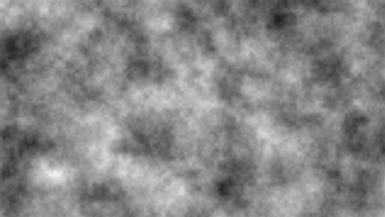
FIG 9.6 Noise pattern created with the Fractal Noise effect when applied to a solid layer.
Noise created by Fractal Noise and Turbulent Noise is not generally used as is, but is combined with other effects. For example, if you apply the Fractal Noise effect to a solid layer, blur the result, and combine it with a lower layer through the Screen blending mode, you can create the illusion of smoke or fog (Figure 9.7).
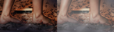
FIG 9.7 Left: Original footage. Right: Fog added by adjusting a Fractal Noise effect. A project file is included as fractal_fog.aep in the ProjectFiles aeFilesChapter9 tutorial directory.
Fractal Noise and Turbulent Noise effects carry an identical list of properties. By default, Turbulent Noise creates a softer noise pattern. Critical properties for both effects are discussed here:
Scale The Scale property, in the Transform section, affects the size of the noise “grains.” Larger Scale values create the illusion that the camera is zooming in to the noise field.
Complexity This slider determines how many different noise patterns are combined to create a more complex pattern. Each pattern that is added is at a different scale, which allows the combination of small and large detail. If Complexity is set to 1.0, the pattern appears smooth. The higher the Complexity value, the more ragged the light and dark edges of the noise grains.
Evolution By default, the noise pattern is static. However, animating the Evolution rotation over time causes the pattern to shift. This creates the illusion that the camera is flying though three-dimensional noise or that different “slices” of a three-dimensional noise are sampled with each frame. If you prefer that the noise simply drifts in one direction, make the noise layer larger than the composition layer and animate its Position X or Position Y over time.
Fractal Type and Noise Type You can create different styles of noise by altering these menus. For example, to create pixelated noise, change the Noise Type menu to Block.
Note that Turbulent Displace, found in the Effect > Distort menu, uses a hidden fractal noise pattern to distort a layer. Hence, it shares many of its attributes with Fractal Noise. The Turbulent Displace effect is discussed in the section “Overview of Distortion Effects” later in this chapter.
Adding Other Film and Video Artifacts
In addition to grain and noise, motion picture film and video suffer from various artifacts discussed in this section. After Effects provides numerous tools and effects which you can use to emulate the artifacts.
Scratches, Dirt, Debris, and Dropout
Motion picture film stock suffers from scratches as positive prints are run through projectors. Alternatively, film negatives may be scratched during processing. Film stocks may also pick up dirt and debris, such as hairs, through extensive handing. Scratches and debris on positive prints appear dark as they block the projector light or interfere with the digital scanning process (left side of Figure 9.8). Scratches and debris that attach itself to a negative appear white as they interfere with processing.
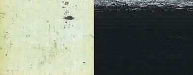
FIG 9.8 Left: Vertical scratches and dirt on a positive film print with an overexposed background. Right: Dropout on analog video, as seen against black.
Although analog videotape doesn’t suffer from scratches or display specific pieces of debris, it may be affected by dropout. Dropout occurs when magnetic data is missing through damage or wear to the tape. Dropout creates white lines, horizontal distortions, and associated static (right side of Figure 9.8).
An efficient way to create the look of scratches, dirt, debris, and dropout is to blend scanned motion picture footage or captured video footage with a layer that requires the artifacts. For example, in Figure 9.9 motion picture footage of a white, overexposed background is combined with a nondamaged layer. The motion picture footage is placed on top and its layer-blending mode is set to Multiply.
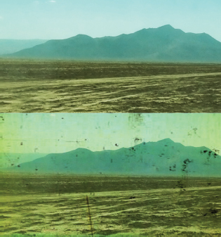
FIG 9.9 Top: Video layer with no damage. Bottom: Dirt and discoloration added with the Multiply blending mode.
Stock footage providers generally offer clips that contain scratched and dirtied film, video static, or blank video with dropout. The scratched footage featured in Figure 9.9 is included as ScratchesDirt.##.png in the ProjectFilesPlatesNoiseGrainScracthesScratchesDirt directory. A project file is included as dirt.aep in the ProjectFilesaeFilesChapter9 tutorial directory.
As motion picture film prints age, they tend to shrink unevenly. This causes the film prints to weave back and forth as the print is fed through the projector. You can re-create this left-right motion by animating the Position X of a layer (Figure 9.10). To avoid seeing empty edges on the frame left and right side, the layer must be scaled larger than the current composition. Although scaling over 100 percent may lead to degradation of the layer, a small-scale increase, such as 102 percent, is generally acceptable. You can also nest a larger-resolution composition into a smaller-resolution composition to create a similar overhang. For more information on nesting, see Chapter 4.
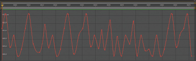
FIG 9.10 Film weave is simulated by creating semirandom left-right motion for a layer. The layer’s X Position curve, as seen in the Graph Editor, moves the layer between 0 and 3 pixels with each frame. A sample project file is included as film_weave.aep in the ProjectFilesaeFilesChapter9 tutorial directory.
Halation, Glow, Glint, and Glare
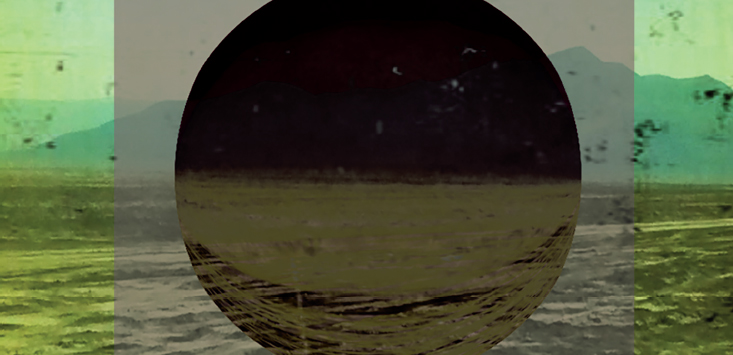
Halation is the spreading of light around bright areas of an image. This often results from light bouncing off substrates of motion picture film and photographic film stock. In contrast, glow occurs when light bounces off participating media in the air, such as fog, haze, smoke, water vapor, and so on (Figure 9.11).
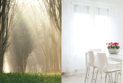
FIG 9.11 Left: Glow created by participating media in the form of haze. Right: Glare from a window erodes the window frame and nearby walls. Left photo © Ping Phuket/Dollar Photo Club. Right photo © Lulu/Dollar Photo Club.
Glints and glares occur when a bright subject, such as a bright lamp or the reflection of the sun off glass, overexposes the immediate area around the subject (Figure 9.10). Glint varies from glare in that glints come and go in brief flashes. For example, the sun may glint off rippling water.
After Effects provides the Glow effect to create halation, glow, and glare (this is found in the Effect > Stylize menu). To adjust the Glow effect, follow these basic steps:
1. Reduce the Glow Threshold to determine what part of the frame glows (Figure 9.12). Pixels with values above the Glow Threshold are included in the glow.
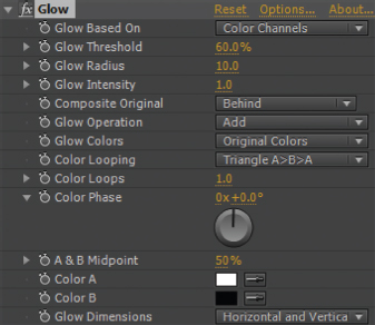
FIG 9.12 Glow effect properties.
2. Adjust the glow brightness by altering Glow Intensity. Alter the softness of the halation and its spread by adjusting the Glow Radius property (Figure 9.13).
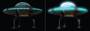
FIG 9.13 Left: Unaltered layer. Right: Halation created with the Glow effect. This project is included as glow.aep in the ProjectFilesaeFilesChapter9 tutorial directory.
3. By default, the glow colors are based on the original pixels. However, you can select your own colors by switching the Glow Colors menu to A & B Colors and changing the Color A and Color B color swatches.
Note that the glow may extend past the alpha matte edge. Depending on the colors that are used to create the glow, this may create an edge glow that is darker than the colors in lower layers. As an alternative to the Glow effect, you can create your own custom glow with these steps:
1. Duplicate the layer that requires the glow. Select the higher of the two identical layers and apply one or more color effects, such as Brightness & Contrast or Curves, and a blur effect, such as Gaussian Blur or Fast Blur.
2. Use the color effect to make the higher layer significantly brighter. Use the blur effect to blur the higher layer (Figure 9.14).
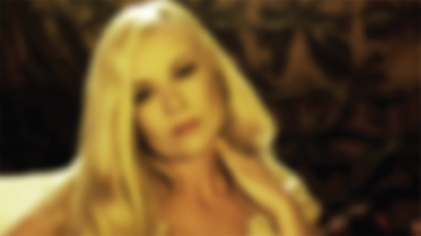
FIG 9.14 A blurred, brightened duplicate of a layer is the first component of a custom glow effect.
3. Switch the higher layer’s blending mode to Screen. This allows the bright areas of the layer to show over the original layer. The glow is created (Figure 9.15). If the glow is too intense, reduce the Opacity value of the higher layer.

FIG 9.15 Left: An unaltered layer that requires glow. Right: The resulting custom glow after a duplicate layer is blurred, brightened, and combined with the Screen blending mode. This project is included as glow_custom.aep in the ProjectFilesaeFilesChapter9 tutorial directory.
When light bounces through the internal mechanism of a lens, it may create a lens flare. Although this phenomenon is related to halation, lens flares often take on specific shapes that relate to the specific lens. For example, common prime lenses, such as 35mm, create the typical chain of hexagonal spots (the hexagonal shape is the shape of the camera aperture). Anamorphic Cinemascope lenses, on the other hand, form horizontal streaks. After Effects provides the Lens Flare effect (Effect > Generate) to create hexagonal- or circular-style flares (Figure 9.16). With this effect, you can choose between three lens types, the flare brightness, and flare origin within the frame. Other plug-ins, such as Video Copilot Optical Flares, Boris FX Lens Flare 3D, and Sapphire LensFlare, offer additional options to create more realistic custom flares.
When motion picture film or analog videotapes age, they often degrade. This may cause the original colors to shift. For example, certain motion picture print stocks tend to lose contrast and become more red with age. You can re-create fading and color shifting through color grading techniques, which are detailed in Chapter 8.
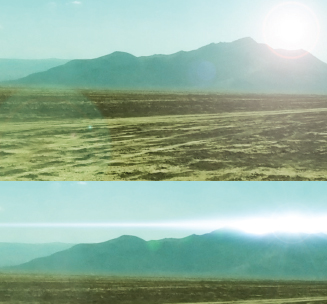
FIG 9.16 Top: Flare created with the After Effects Lens Flare effect. Bottom: Cinemascope-style flare created with Boris FX Lens Flare 3D.
Older forms of motion picture film, analog video, and digital video captured their images through different mechanical, chemical, magnetic, optical, and/or digital processes. As such, each form of film and video capture technology utilized a different color space. For example, the colors in a Technicolor film print appear significantly different from a Kodak Safety film print—even if the same subject with the same lighting was recorded. Along those lines, analog videotape may appear different than 8-bit digital video and both formats may appear dissimilar to 10-bit digital video. Hence, it may be necessary to replicate the color space of a specific capture technology. This becomes a challenge when the technology is no longer used. For an example of this challenge, see the tutorial at the end of the chapter.
Several effects in After Effects employ median filters and can be used to reduce noise, grain, and small, pixel-sized elements, such as dust, dirt, and short scratches. The effects may also be useful for creating stylized results. For example, the Median effect (in the Effect > Noise & Grain menu), averages pixel values through a convolution filter. The averaged values are halfway between the highest and lowest values within the convolution filter sample area (essentially a small window that slides over the image). This results in a softening of the image, which tends to remove small variations in pixel values. The effect includes a Radius property, which determines the pixel size of the convolution filter. Large property values cause heavy averaging, thus creating a painterly look (Figure 9.17). For the effect to successfully reduce noise or grain without affecting the layer in an excessively detrimental way, the source footage must be high resolution.
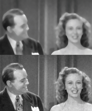
FIG 9.17 Top: Grainy footage with a Medium Radius set to 5. Bottom: Same footage with Radius set to 1.0. This project is included as median.aep in the ProjectFilesaeFilesChapter9 tutorial directory.
The Dust & Scratches effect (Effect > Noise & Grain) also applies a median filter in an attempt to reduce noise and grain. However, the effect includes a Threshold property, which sets the degree of contrast between sampled pixels required to average an area within the convolution filter window. This sensitivity allows the effect to maintain sharper edges on shapes within the image.
After Effects includes a set of paint tools that allow you to paint strokes on a layer (see Figure 9.20 later in this chapter). Each stroke is based on a specialized spline. You can create solid-colored strokes or clone color values from the current layer or a different layer. You can use the strokes to create motion graphic shapes, such as text, or use the strokes as part of a paint fix. Paint fixes remove unwanted elements from an image or otherwise “repair” problematic footage.
To create a paint stroke on a layer, follow these steps:
1. Switch to the Layer view by double-clicking a layer. A stroke must be attached to a particular layer. The Layer view is distinguished from the Composition view in that it carries an embedded timeline and playback controls.
2. Click the Brush tool button in the top program toolbar (Figure 9.18). LMB-drag a stroke in the viewer. Release the mouse button to end the stroke. A colored line is drawn along the stroke. The spline defining the line is hidden initially.

FIG 9.18 The Brush, Clone Stamp, and Eraser tool buttons, found in the top program toolbar.
3. To create another stroke, repeat step 2. Before drawing a stroke, you can alter the stroke’s basic properties through the Paint panel at the bottom right of the program window (see Figure 9.21 later in this chapter). If the panel is not visible, choose Window > Paint. The properties include color and opacity. Note that the color of the resulting line is set by the Set Foreground Color swatch (the top left swatch box).
Each stroke you draw is added as Brush n to the Effects > Paint subsection of the layer.
Editing a Stroke’s Color, Opacity, and Softness
Properties set by the Paint panel appear in the Effects > Paint > Brush n > Stroke Options subsection of the layer and may be changed after the stroke is drawn. The properties include Color, Opacity, and Diameter, which sets the line width (Figure 9.19).

FIG 9.19 The Stroke Options subsection of a Paint tool stroke, as seen in the layer outline.
In addition, you can find these unique properties:
Start and End By default, the colored line runs the entire length of the stroke you interactively draw with the Brush tool. However, you can raise the Start value so that the colored line starts later. Conversely, you can lower the End value so that the line ends sooner. You can animate Start and End over time so that it appears as if the line is drawn as the timeline moves forward. This creates the illusion of handwriting and may be useful for animated motion graphics.
Hardness and Flow Hardness controls the line softness, with higher values making the line hard-edged. Flow sets the opacity of individual shapes used to create the stroke line. Flow values lower than 100 percent cause the line to appear softer—even when Hardness is set to 100 percent.
Spacing, Roundness, and Angle A line created by a stroke is actually a series of overlapping shapes. If you raise the Spacing value, the shapes are spread out over the stroke with larger gaps. When the Roundness property is set to 100 percent, the shapes are circles. When you lower the Roundness, the shapes become more oval-like. If you lower the Roundness and Spacing to 0 percent, the line varies in width in a fashion similar to a line drawn by a calligraphy pen. You can alter the areas of the line that becomes thin and flattened out by adjusting the Angle property.
Blending Mode By default, a stroke created with the Brush or Clone tool is combined with its layer through the Normal blending mode. However, you can change the blending mode menu, beside the Brush n name in the layer outline, to any other mode.
Transforming and Erasing a Stroke
Each stroke added to a layer carries an Effect > Brush n > Transform subsection. The transform properties are similar to a standard layer and include Anchor Point, Position, Scale, and Rotation. You can animate these properties.
The Anchor Point of a stroke is located at the start of the stroke. However, the stroke itself, which is the specialized spline, is only visible if you select the Brush n section name in the layer outline (Figure 9.20). You can interactively move the stroke in the viewer by returning to the Selection tool and LMB-dragging the stroke spline or its Anchor Point. To delete a stroke, select it in the layer outline and press the Delete key. You can add as many strokes as you like to a single layer by returning to the Brush tool.
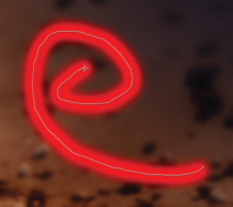
FIG 9.20 A selected stroke reveals its associated spline, which is colored white.
By default, a stroke exists for the entire duration of the timeline. However, you can alter this behavior by changing the Duration menu in the Paint panel before drawing the stroke (Figure 9.21). If you set Duration to Single Frame, the drawn stroke exists on the timeline for one frame. If you set Duration to Custom, you can choose a duration through the frame field directly to the right of the menu. If you set Mode to Write On, the program animates the End property so that the colored line is revealed over time (see the previous section). Returning Duration to Constant ensures that the stroke starts on the frame it was painted and continues to the end of the timeline. You are free to alter the duration of any drawn stroke by LMB-dragging the end of the stroke’s duration bar in the timeline panel.
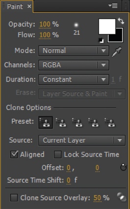
FIG 9.21 The Paint panel.
If you create a stroke with the Eraser tool, the resulting stroke cuts a hole through any other stroke that crosses its path. In addition, the eraser stroke cuts a hole into the current layer. When you switch back to the Composition view, the hole reveals lower layers. Thus, the Eraser tool offers a means to remove parts of a frame that may otherwise be cut out through a masking/rotoscoping process. An eraser stroke receives an Eraser n subsection on the layer and carries the same properties as a stroke created with the Brush tool.
The Clone Stamp tool allows you to sample one area of the frame and paint it as a stroke in a different area. This is ideal for making paint fixes and similar repairs to footage. To apply the tool, follow these steps:
1. Switch to the Layer view by double-clicking a layer. A stroke must be attached to a particular layer.
2. Click the Clone Stamp tool in the program toolbar (Figure 9.18 earlier in this chapter). Place the mouse over an area you wish to clone and press the Alt/Opt key. Move the mouse to the area you wish to paint the stroke and LMB-drag to create a stroke. Release the mouse button to end the stroke. Note that the Clone Stamp tool clones any other stroke that may exist on the layer.
A Clone n subsection is added to the layer when a Clone Stamp stroke is drawn. The included properties are identical to a Brush tool stroke with the addition of several Clone properties. By default, the Clone Source menu is set to the current layer. However, you can switch this menu to a different layer. This may be useful when sampling a clean plate or footage that doesn’t include the artifact or element you’re trying to paint over. (A clean plate is a variation of a shot that removes actors and props in favor of an empty set.) The Clone Position property indicates the XY position where you press the Alt/Opt key to establish the clone source origin for the stroke. Clone Time Shift allows you to offset the frame that’s used for the clone source. This is useful when painting over dust, scratches, and other debris that may appear briefly within the frame. For a demonstration of dust removal, see the mini-tutorial at the end of this section.
The Paint panel provides readout options to refine the application of the Clone Stamp tool. The Offset X and Y fields display the distance from the cloned point to the point where you begin the current stroke. The Aligned check box, when selected, offsets each painted stroke so each stroke stays relative to the last point sampled. This allows you to cover a large area without having to resample with each stroke. If Aligned is deselected, each stroke uses the same sampled point and no offsetting occurs. In general, the Aligned option is desirable when creating paint fixes to cover up or remove unwanted elements.
The Preset buttons, on the other hand, memorize the current Clone Stamp settings when a Preset button is clicked. You can switch between any of the Preset buttons at any time. The buttons provide an efficient means to jump between settings when creating extensive paint fixes. In addition, the Paint panel includes a Source menu and Source Time Shift property that allows you to set their namesakes before drawing the stroke. Additional brush options are included in the Brushes panel and are discussed in the following tutorial.
Removing film damage mini-tutorial
The Clone Stamp tool provides a means to interactively remove dust, scratches, and similar damage from footage. For example, as seen in Figure 9.1 at the start of this chapter, a digital transfer of amateur motion picture film reveals such damage. To apply the Clone Brush tool to this footage, follow these steps:
1. Create a new project. Import Title.##.png in the ProjectFilesPlatesNoiseGrainScracthesTitle directory. Interpret the image sequence so that it is read at 24 fps. Place the image sequence into a new composition that is 960x720 resolution, 24 fps, and 32 frames in duration.
2. Play back the timeline and examine individual frames. Many pieces of dust appear for a single frame (Figure 9.22). Scratches appear longer and constantly shift. Double-click the layer so that it opens in the Layer view. Return to frame 1. Play forward, one frame at a time, until you identify a distinct black spot created by dust. For example, on frame 15, a black spot appears in the sky.
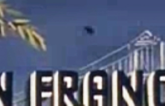
FIG 9.22 A piece of dust appears like a black dot in the sky. Also note the appearance of compression blocks beside the dust and the building. The blocks were created by the digital compression when the film footage was transferred.
3. While the layer is visible in the Layer view, select the Clone Stamp tool from the main toolbar. Adjust the size of the brush by using the Brushes panel (Window > Brushes). You can choose a preset brush from the top of the panel or select a particular Diameter value. If you’re using a stylus to paint, you can set stylus-specific traits such as angle and roundness. You can reduce the softness of the brush edge by raising the Hardness value. For this tutorial, make the brush soft-edged and slightly larger than the dust spot.
4. In the Paint panel (Window > Paint), set Duration to Single Frame. In the Layer view, place the mouse to the left of the dust spot (to the right of the tree and over the blue sky). Press Alt/Opt and the left mouse button to sample that area of the frame. LMB-drag over the dust spot to create a short stroke. The Clone Stamp color, sampled from the sky, covers the spot. Optionally, you can make the stroke long enough to cover up the compression blocks to the left of the spot.
5. Expand the Effects > Paint section of the layer in the layer outline. The stroke is listed as Clone 1. Select the Clone 1 name. The stroke spline is revealed in the viewer (Figure 9.23). Note that the footage bar beside Clone 1 in the timeline has a one-frame duration.
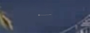
FIG 9.23 A Clone Stamp stroke covers the dust spot for one frame.
6. Step forward one frame at a time and identify a new piece of dust. Repeat steps 3 and 4 to remove the dust. (If the prior Clone stroke is selected in the layer outline, the old stroke is updated with the new one.) Continue this process, repairing as many spots as possible. Some frames include slightly larger patches of dirt. In such a situation, you can create a large brush or, alternatively, paint multiple corrective strokes on the same frame. Some dirt and dust may last two or three frames due to the nature of the film transfer. As such, you are free to LMB-drag the ends of the stroke duration bars to make the strokes last additional frames (Figure 9.24).
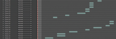
FIG 9.24 Multiple Clone Stamp strokes are painted on a layer. Their durations are adjusted to last one or two frames.
Some areas of the footage are heavily dirtied or stained. For example, frames 20 through 22 reveal dirt spots along the top and bottom left of the footage. There are several approaches you can take to repairing these areas:
• If a problem area is only affected by dirt for a few frames, you can sample pixels from an earlier or later frame on the timeline that might be dirt-free. To do so, change the Source Time Shift property in the Paint panel. For example, if you change the property to –1, the pixels are taken from the previous frame. This allows you to take a sample directly over the dirtied area when Alt/Opt + LMB-clicking. Note that the Source Time Shift property resets itself to 0 after each stroke is painted. To use this option more efficiently, I recommend Alt/Opt+LMB-clicking to sample the frame, changing the Source Time Shift value, and then LMB-clicking to draw a stroke. To preview the source layer with an offset time, you can raise the Clone Source Overlay value to 100 percent. This displays the source while your mouse hovers over the Layer view. The Clone Source Overlay property is located at the bottom of the Paint panel.
• Alternatively, you can use the Eraser tool to cut out the dirtied area and reveal a lower, clean layer. For example, place another copy of the footage on a lower layer, offset the new, lower layer so that it starts a few frames sooner, and use the Eraser tool to cut holes in the old, upper layer (Figure 9.25). When you return to the Composition view, the lower layer shows through the holes. An example file that uses this technique is included as mini_clone_stamp.aep in the ProjectFilesaeFilesChapter9 tutorial directory.
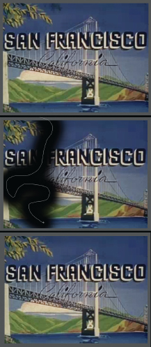
FIG 9.25 Top: Original footage showing a dirtied area at the left and top left side of the frame. Center: In the Layer view, a large Eraser stroke is drawn to cut out the problem area. Bottom: As seen in the Composition view, a second copy of the footage is placed on the lower layer and is offset by a few frames to reveal a clean area through the new hole.
Note that these two techniques only work if the camera is not moving. Nevertheless, you can apply either of these techniques when removing scratches from a static shot. For an example of this, see Figure 9.1 at the start of this chapter. Keep in mind that the paint fix repairs may never be perfect; however, you can significantly reduce the appearance of dust, dirt, scratches, and other unwanted elements (such as those discussed in the section “Adding Other Film and Video Artifacts” earlier in this chapter).
The film footage in this section is taken from Amateur film: Summers collection: San Francisco, California, 1941 (Part I), which is part of the Prelinger Archives, made available via a Creative Commons Public Domain license. For more information, visit www.archive.org/details/prelinger.
Overview of Distortion Effects
After Effects includes a long list of distortion effects with the Effect > Distort menu designed to alter pixel positions within a layer. Although these effects are not strictly designed to replicate film and video artifacts, they can replicate some unique phenomena captured by film and video cameras. Here are a few examples of their application.
This effect displaces a layer based on the intensity values of a built-in fractal noise pattern. The distortion may be useful for replicating undulating substances or surfaces, such as the swelling of water, the movement of fabric in wind, or the optical distortions to air caused by heat rising off the ground. For example, you can create heat wave distortions by applying the effect to a semi-opaque copy of a layer (Figure 9.26).
The built-in noise of the effect is controlled by properties similar to those carried by the Fractal Noise and Turbulent Noise effects (see the “Using Perlin Noise” section earlier in this chapter). The strength of the displacement is set by the Amount property. The size of the noise “grains” is set by the Size property. By default, the noise and displacement is static. However, you can animate the Evolution property increasing over time to create the undulation.
This effect mimics the spherical edge distortions created by some lenses. You can use this effect to match undistorted layers to footage that carries the lens distortion. The Field Of View (FOV) property controls the degree of distortion, with higher values pulling the outer edges inwards. If you select the Reverse Lens Distortion check box, the distortion becomes concave and the edges are pushed outwards (Figure 9.27). You can use the effect with a high Field Of View (FOV) value to stylistically create a “fish eye” lens or “tiny planet” effect. Note that you may need to nest the resulting layer due to the shrinking of the image and the appearance of empty black edges.
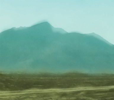
FIG 9.26 Close-up of a heat wave effect created by placing a semi-opaque copy of a layer at the top of the layer outline with the Turbulent Displace and Fast Blur effects. This project is included as heat_displace.aep in the ProjectFilesaeFilesChapter9 tutorial directory.
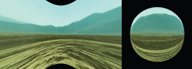
FIG 9.27 A landscape is distorted with the Optics Compensation effect. The Reverse Lens Distortion option causes concave distortion (left), while a high Field Of View (FOV) creates a “fish eye” effect (right). This project is included as optics_compensation.aep in the ProjectFilesaeFilesChapter9 tutorial directory.
This effect creates a spherical, convex distortion. If the Size and Convergence properties are set to high values, the result is similar to a light probe map, a specialized spherical mapping created with High Dynamic Range (HDR) photographs intended for HDR lighting within a 3D program. (For more information on HDR, see Chapter 8.)
Several additional distortion effects provide a means to interactively “push” pixels. Although these are not intended to replicate particular real-world phenomena, they are often useful for common visual effects tasks. These are discussed briefly here.
The Mesh Warp effect allows you to push pixels around by interactively LMB-dragging a grid overlay in the view panel. The Liquify effect also allows you to push pixels, but provides a wide range of brushes to complete the task. The brush tools are contained within the Effect Controls panel and include Push, Turbulence, Twirl, Pucker, and Bloat. Both of these effects allow you to animate the distortion over time (select the Distortion Mesh check box). Hence, they are suitable for warping an element within a frame. For example, you can use Liquify to bend the fender of a car to simulate the impact of a piece of debris thrown out by an explosion.
This effect provides a more accurate means to upscale (scale a layer over 100 percent). If you switch the Alpha property menu to Detail Preserving and raise the Detail property value, a large Scale value is able to preserve more edge detail than the standard bicubic upscale applied by the layer’s Scale transform.
This effect reduces the presence of rolling shutter artifacts (diagonal distortions in moving objects caused by the vertical or horizontal scanning of a frame employed by some digital cameras).
In addition, the Wave Warp effect creates a sine-wave distortion. This is demonstrated in the following tutorial.
Chapter Tutorial: Emulating Low-Quality Video Footage
Sometimes, for stylistic reasons, it’s desirable to intentionally degrade your work in After Effects. This might be necessary to match new elements to old motion picture or video footage or to make new footage look like it was shot in a different time period or with different equipment. For example, with this tutorial we can take high-quality HD video footage and make it look like it was shot with a standard-definition, black-and-white security camera. Follow these steps:
1. Create a new project. Import the 1_3a_2look.###.png image sequence from the ProjectFilesPlatesColorGrading1_3a_2look directory. Create a new composition that’s 1920x1080, 24 fps, and 48 frames in duration. LMB-drag the image sequence into the new composition.
2. With the new layer selected, add Hue/Saturation, Curves, and Brightness & Contrast effects. With the Hue/Saturation effect, reduce Master Saturation to –100 to convert the sequence to grayscale. With the Curves effect, add one point to the center of the curve and bow the curve center upwards to brighten the midtones and highlights. With the Brightness & Contrast effect, set Brightness to 125 and Contrast to 100. You can combine multiple color correction effects to create more extreme results. With this series of steps, the dynamic range of the image is intentionally reduced with some areas pushed to the maximum value of 255 (Figure 9.28). A limited dynamic range emulates poor-quality video cameras.

FIG 9.28 HD video footage desaturated and given increased brightness and contrast.
3. Add a Fast Blur effect. Set Blurriness to 3. Additional image softness emulates a low-quality lens or video sensor. With the layer selected, choose Edit > Duplicate. Select the new, upper layer and set the Blurriness of the Fast Blur effect to 30. Set the top layer’s blending mode to Screen. Reduce the top layer’s Opacity to 75 percent. This series of steps creates a halation-like glow over the old frame, another indication of a low-quality lens.
4. Create a new composition that is 640x480, 24 fps, with a 48-frame duration. 640x480 was the standard resolution of pre-digital, analog standard-definition television. Nest the first composition within the new composition. The first composition overhangs. Reduce the scale of the new layer to 50 percent and position the layer to center the actress (Figure 9.29).
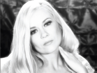
FIG 9.29 The first composition, which has a custom glow added to it, is nested in a second, smaller composition.
5. With the layer selected, choose Effect > Distort > Wave Warp. The effect distorts the layer with a sine-wave pattern. By default, the distortion is vertical, so that it looks like the image is melting. Change the Direction property to 0 degrees. The distortion becomes horizontal. Change Wave Width to 5. This narrows each wave peak and valley. The result is similar to analog video interlacing. Increase the Wave Height. The image is pulled apart to the left and right as if interlaced lines are separated (Figure 9.30).
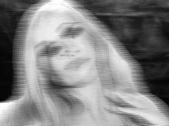
FIG 9.30 The result of the Wave Warp effect with Direction set to 0, Wave Width set to 5, and Wave Height set to 50.
6. Activate the Time icon for Wave Height and randomly animate its values changing over the timeline. Play back and adjust the animation. These steps re-create poor reception or other interference suffered by analog video systems. Add a Fast Blur effect to the layer and set Blurriness to 4. This softens the edges of the sine peaks and valleys.
7. Create a new solid, making it the same size as the composition. Set the solid to a medium gray color. Move the solid to the top of the layer outline. With the solid layer selected, choose Effect > Noise & Grain > Noise. Change the effect’s Amount Of Noise property to 100 percent. Deselect the Use Color Noise property. Fine, grayscale noise appears over the solid and is pre-animated so it shifts over time.
8. Change the solid layer’s blending mode to Screen. Animate the solid’s Opacity, changing it from 5 percent to 50 percent over time. Match the animation to the animation of the Wave Height of the Wave Warp effect. When Wave Height is high, make the solid’s Opacity high and vice versa. The result further emulates poor analog reception. Scale the solid layer up to 200 percent. This creates larger noise “grains.” Play back. The footage shifts from moderate quality to low quality in a random fashion (Figure 9.31).
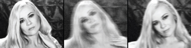
FIG 9.31 A Noise effect adds its namesake to a gray solid layer, which is screened over the footage of the actress. Animation of the Wave Warp effect’s Wave Height and the Opacity of the solid layer creates a shifting quality.
A finished version of this project is saved as low_quality_video.aep in the ProjectFilesaeFilesChapter9 directory.