9
Using Common Design Patterns
The previous chapters described general techniques for building database designs. For example, Chapter 5, “Translating User Needs into Data Models,” explained how to build semantic object models and entity-relationship diagrams for a database, and how to convert those models into relational designs. Chapter 7, “Normalizing Data,” explained how to transform those designs to normalize the database.
This chapter takes a different approach. It focuses on data design scenarios and describes methods for building them in a relational model.
In this chapter, you will learn techniques for:
- Providing different kinds of associations between objects
- Storing data hierarchies and networks
- Handling time-related data
- Logging user actions
This chapter does not provide designs for specific situations such as order tracking or employee payroll. Appendix B, “Sample Relational Designs,” contains those sorts of examples.
This chapter focuses on a more detailed level to give you the techniques that you need to build the pieces that make up a design. You can use these techniques as the beginning of a database design toolbox that you can apply to your problems.
The following sections group these patterns into three broad categories: associations, temporal data, and logging and locking.
ASSOCIATIONS
Association patterns represent relationships among various data objects. For example, an association can represent the relationship between a rugby team and its opponents during matches.
The following sections describe different kinds of associations.
Many-to-Many Associations
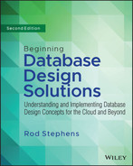
It's easy to represent a many-to-many association in an ER diagram. For example, a Student can be enrolled in many Courses and a Course includes many Students, so there is a many-to-many relationship between Students and Courses. Figure 9.1 shows an ER diagram modeling this situation.
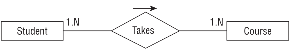
Unfortunately, relational databases cannot handle many-to-many relationships directly. To build this kind of relationship in a relational database, you need to add an association table to represent the relationship between students and courses. Simply create a table called StudentCourses and give it fields StudentId and CourseId. Figure 9.2 shows this structure.
To list all of the courses for a particular student, find the StudentCourses records with the required StudentId. Then use each of those records' CourseId values to find the corresponding Courses records.
To list all of the students enrolled in a particular course, find the StudentCourses records with the required CourseId. Then use each of those records' StudentId values to find the corresponding Students records.
Multiple Many-to-Many Associations
Sometimes, a many-to-many relationship contains extra associated data. For example, the previous section explained how to track students and their current course enrollments. Suppose you also want to track student enrollments over time. In other words, you want to know each student's enrollments for each year and semester. In this case, you actually need to make multiple many-to-many associations between students and courses. You need whole sets of these associations to handle each school semester.
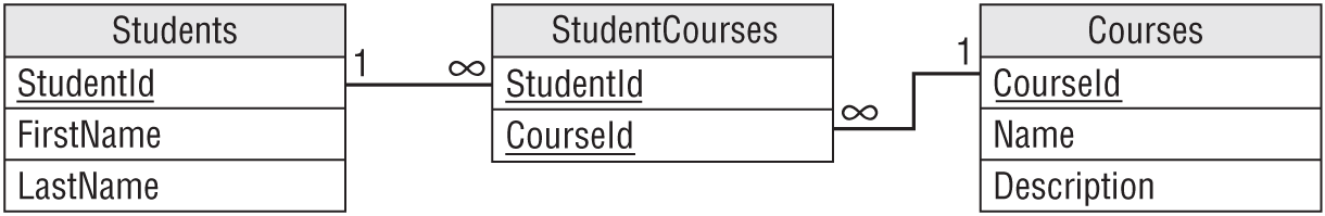
Fortunately, this requires only a small change to the previous solution. The StudentCourses table shown in Figure 9.2 can already represent the relationship of students to courses. The only thing missing is a way to add more records to this table to store information for different years and semesters.
The solution is to add Year and Semester fields to the StudentCourses table. Figure 9.3 shows the new model.
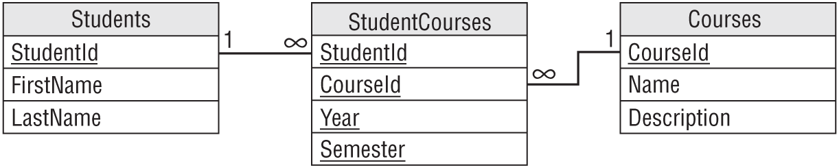
Now, the StudentCourses table can store multiple sets of records representing different years and semesters.
If you need to store extra information about each semester, you could make a new Semesters table to hold that information. Then you could add the Year and Semester fields to this new table and use them as a foreign key in the StudentCourses table.
Multiple-Object Associations
A multiple-object association is one where many different kinds of objects are collectively associated to each other. For example, making a movie requires a whole horde of people, including a director, a bunch of actors, and a huge number of crew members with improbable titles like gaffer, dolly grip, best boy, and python wrangler. (No, I didn't invent any of those.) You could model the situation with the ER diagram shown in Figure 9.5.
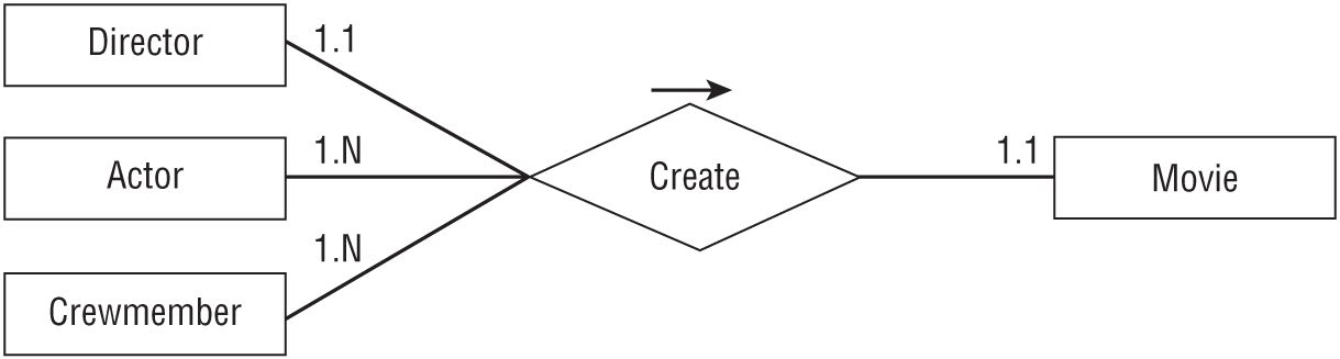
If this collection of people always worked as a team, then this situation would be easy to implement in a relational model. You would assign all of the people a TeamId, and then build a Movies table with a TeamId field to tell who worked on that movie.
Unfortunately, this idea doesn't quite work because all these people can work on any number of movies in any combination.
You can solve this problem by thinking of the complex multi-object relationship as a combination of simpler relationships. In this case, you can model the situation as a one-to-one Director/Movie relationship, a many-to-many Actor/Movie relationship, and a many-to-many Crewmember/Movie relationship.
Figure 9.6 shows the new ER diagram.
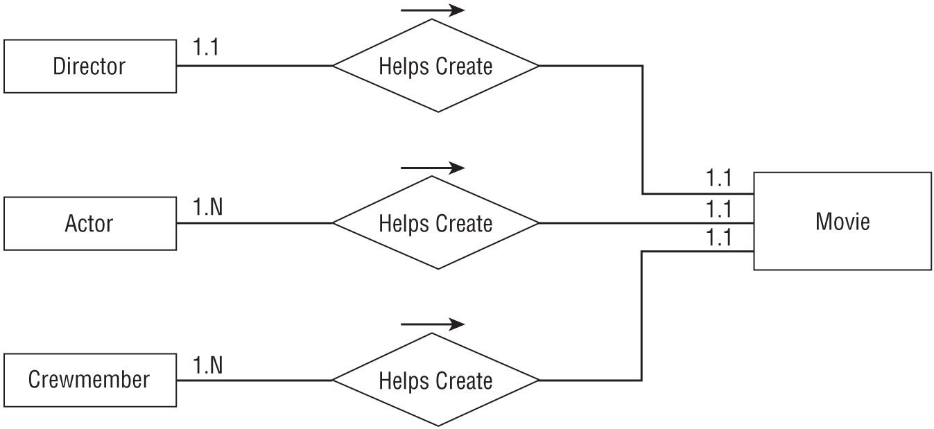
You can convert this simpler diagram into a relational model, as shown in Figure 9.7.
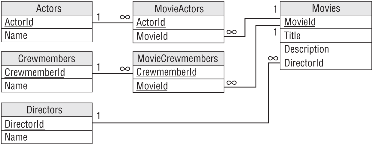
Notice that this model uses two association tables to represent the two many-to-many relationships. The relationship between Directors and Movies doesn't require an association table because this is a simpler one-to-one relationship.
Repeated Attribute Associations
Some entities have multiple fields that represent either the same kind of data or a very similar kind of data. For example, it is common for purchase orders and other documents to allow you to specify a daytime phone number and an evening phone number. Other contact-related records might allow you to specify even more phone numbers for such things as cellphones, emergency contacts, fax numbers, pagers, and others.
Figure 9.10 shows a semantic object model for a PERSON class that allows any number of Phone attributes.
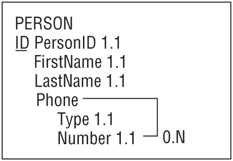
In this model, we want to allow any number of instances of the repeated attribute even if they have the same type. For example, we would allow an order to include multiple emergency contact phone numbers.
To allow any number of repeated attributes in a relational model, build a new table to contain the repeated values. Use the original table's primary key to link the new records back to the original table.
Figure 9.11 shows how to do this for the PERSON class shown in Figure 9.10.
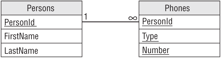
Because the Phones table's primary key includes all of the table's fields, the combination of PersonId/Type/Number must be unique. That means a person can only use a phone number for a particular purpose once. That makes sense. It would be silly to list the same phone number as a work number twice for the same person. However, a person could have the same number for multiple purposes (daytime and evening numbers are the same cell phone) or have multiple phone numbers for the same purpose (office and receptionist numbers for work phone).
You can use the primary keys and other keys to enforce other kinds of uniqueness. For example, to prevent someone from using the same number for different purposes, make PersonId/Number a unique key. To prevent someone from providing more than one number for the same purpose (for example, two cell phone numbers), make PersonId/Type a unique key.
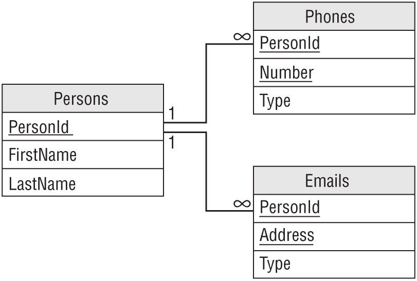
For another example, suppose you want to add multiple email addresses to the Persons table, allow each person to have any number of phone numbers and email addresses of any type, but not allow duplicate phone numbers or email addresses. (For example, you cannot use the same phone number for Home and Work numbers.)
Just as you created a Phones table, you would create an Emails table with Type and Address fields, plus a PersonId field to link it back to the Persons table. To prevent an email address from being duplicated for a particular person, include those fields in the table's primary key. Figure 9.12 shows the new relational model.
Reflexive Associations
A reflexive association or recursive association is one in which an object refers to an object of the same class. You can use reflexive associations to model a variety of situations ranging from simple one-to-one relationships to complicated networks of association.
The following sections describe different kinds of reflexive associations.
One-to-One Reflexive Associations
As you can probably guess, in a one-to-one reflexive association an object refers to another single object of the same class. For example, consider the PERSON class's Spouse field. A Person can be married to exactly one other person (at least in much of the world), so this is a one-to-one relationship. Figure 9.13 shows an ER diagram representing this relationship.
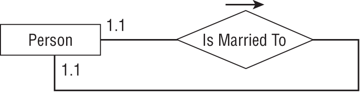
Figure 9.14 shows a relational model for this relationship.
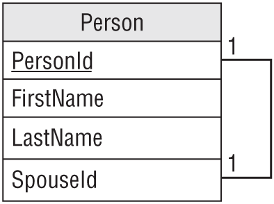
Unfortunately, this design does not require that two spouses be married to each other. For example, Ann could be married to Bob and Bob could be married to Cindy. That might make an interesting television show, but it would make a confusing database.
Another approach would be to create a Marriage table to represent a marriage. That table would hold the IDs of the spouses involved in the marriage. Figure 9.15 shows this design.
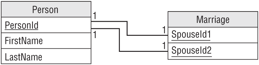
In this design, the Person table refers to itself indirectly.
For another example, suppose you're making a database that tracks competitive rock-paper-scissors matches (see https://wrpsa.com/rock-paper-scissors-tournaments). You need to associate multiple competitors with each other to show who faced off in the big arena. You also want to record who won and what the winning moves were.
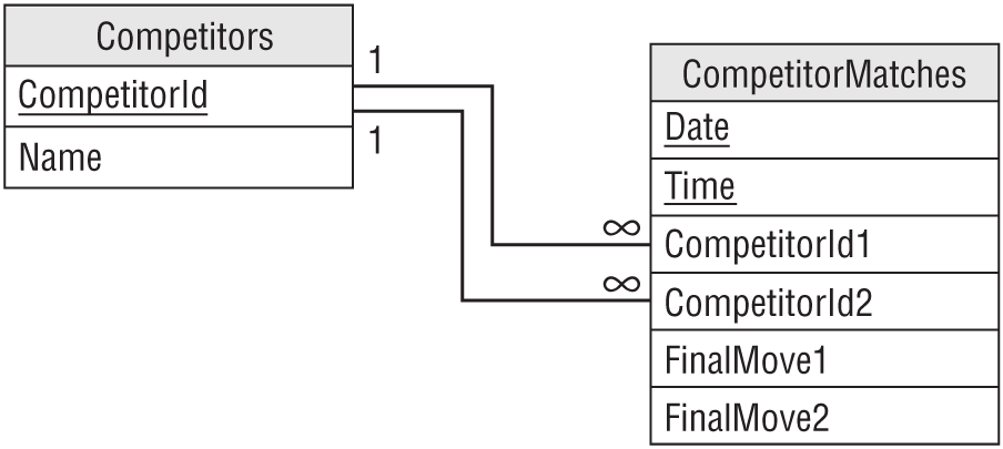
You would start by making a Competitors table with fields Name and CompetitorId.
Next, you would make a CompetitorMatches table to link Competitors. This table would contain CompetitorId1 and CompetitorId2 fields, and corresponding FinalMove1 and FinalMove2 fields to record the contestants' final moves. To distinguish among different matches between the same two competitors, the table would also include Date and Time fields.
Figure 9.16 shows the relational model.
One-to-Many Reflexive Associations
Typically, employees have managers. Each employee is managed by one manager and a manager can manage any number of employees, so there is a one-to-many relationship between managers and employees.
But a manager is just another employee, so this actually defines a one-to-many relationship between employers and employees. Figure 9.17 shows an ER diagram for this situation.
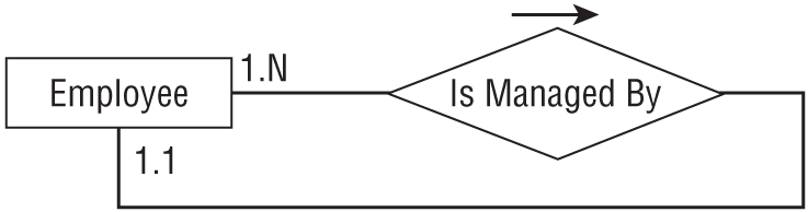
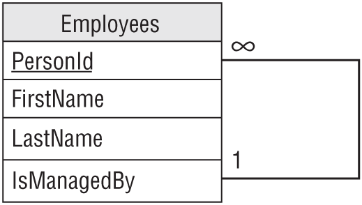
Figure 9.18 shows a relational model that handles this situation.
Hierarchical Data
Hierarchical data takes the form of tree-like structures. Every object in the hierarchy has a “parent” object of the same type. For example, a corporate organizational chart is a hierarchical data structure that shows which employee reports to which other employee. Figure 9.19 shows the org chart for a fictional company.
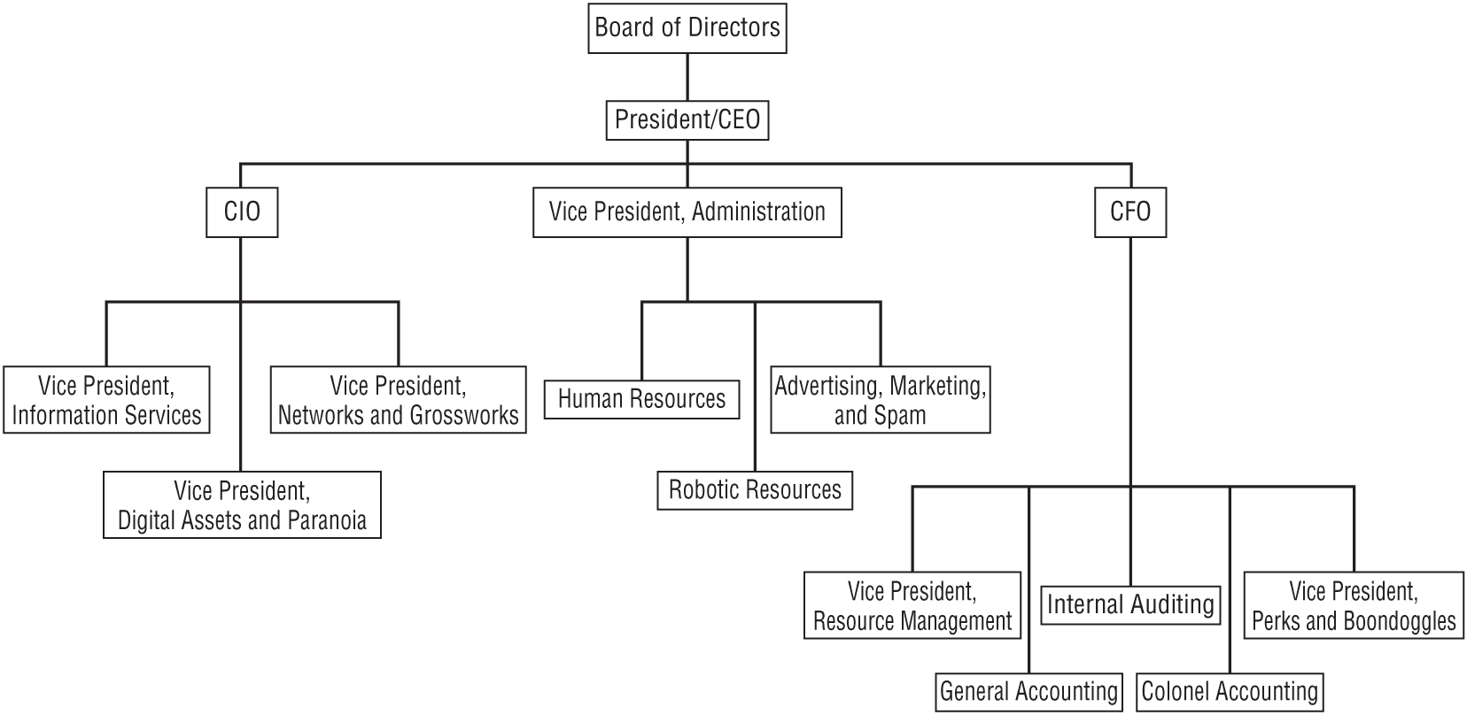
Hierarchical data is an instance of a one-to-many reflexive association as described in the previous section. Generally, people think of the “Is Managed By” relationship as being relatively flat, so managers supervise front-line employees but no one needs to manage the managers. In that case, the hierarchy is very short.
An org chart can also represent the infinitesimally different concept of “Reports To.” I guess this is more palatable to managers who don't mind reporting to someone even if they don't need help managing their own work (although I've known a few managers who could have used some serious help in that respect).
The “Reports To” hierarchy may be much deeper (physically, not necessarily intellectually) than the “Manages” hierarchy, but you can still model it in the same way. Figure 9.20 shows an EMPLOYEE class that can model both hierarchies simultaneously.
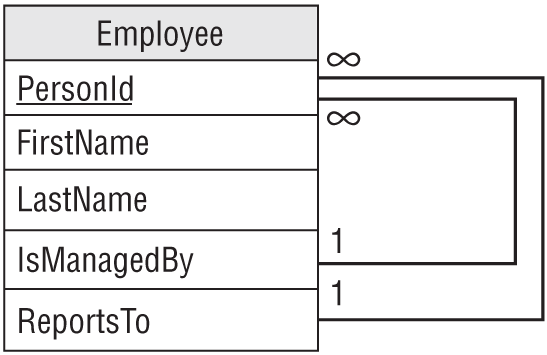
Notice that the relationships used to implement a hierarchy are “upward-pointing.” In other words, each object contains a reference to an object higher up in the hierarchy. This is necessary because each object has a single “parent” in the hierarchy but may have many “children.” Though you can list an object's parent in a single field, you cannot list all of its children in a single field.
This method of building a tree works, but it might require a program to jump all over the database fetching the tree's nodes one at a time, possibly from widely separated parts of the disk drive. If the database is small, that's not a problem. If the database is large, however, then this might force the database to reload the same pages of the hard drive many times, and that can greatly slow the process.
In that case, it might be better to load all the tree information all at once and then process it in memory to build the tree. Alternatively you can consider NoSQL databases.
Hierarchical Data with NoSQL
The preceding section explained how to represent hierarchical data in a relational database. It works fairly well, but relational databases aren't truly intended to work with hierarchical data. However, certain kinds of NoSQL databases are.
A graph database is, as I'm sure you can guess, designed to work with graphs. A graph (which is also called a network) represents objects connected by relationships. For example, a street network represents locations in the real world connected by streets.
The trees described in the previous section are a special case of a graph where each node has at most one parent. That means a NoSQL graph database can represent trees easily. Because those kinds of databases are designed to work with graphs, they might also provide features for searching graphs and therefore trees. For example, you might be able to query the database to find out who reports directly or indirectly to VP Shtick.
The JavaScript Object Notation (JSON) and Extensible Markup Language (XML) file formats are naturally hierarchical, so they can easily store tree-like data. By themselves these are just file formats, but they have been around long enough that there are tools for working with those formats. For example, many programming languages have libraries that can read, write, and search JSON and XML files extremely quickly.
Unless you need relational capabilities, you'll probably get better performance if you store hierarchical data in a NoSQL graph database or in a JSON or an XML file.
Network Data
A network (or graph) contains objects that are linked in an arbitrary fashion. References in one object point to one or more other objects.
For example, Figure 9.22 shows a street network. Each circle represents a node in the network. An arrow represents a link between two nodes. The numbers give the approximate driving times across the links. Notice the one-way streets with arrows pointing in only one direction.
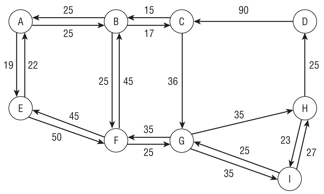
An object cannot use simple fields to refer to an arbitrary number of other objects, so this situation requires an intermediate table describing the links between objects.
Figure 9.23 shows an ER diagram describing the network's Node object. Notice that the Connects To relationship has a LinkTime attribute that stores the time needed to cross the link.
The section “Many-to-Many Associations” earlier in this chapter showed how to build a relational model for many-to-many relationships. That method just needs a small twist to make it work for a many-to-many reflexive relationship.
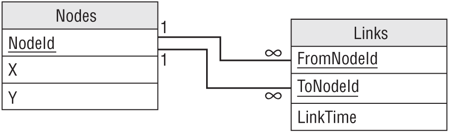
Instead of creating two tables to represent the related objects, just create a single Nodes table. Then create an intermediary Links table to represent the association between two nodes. That object represents the network link and holds the LinkTime data.
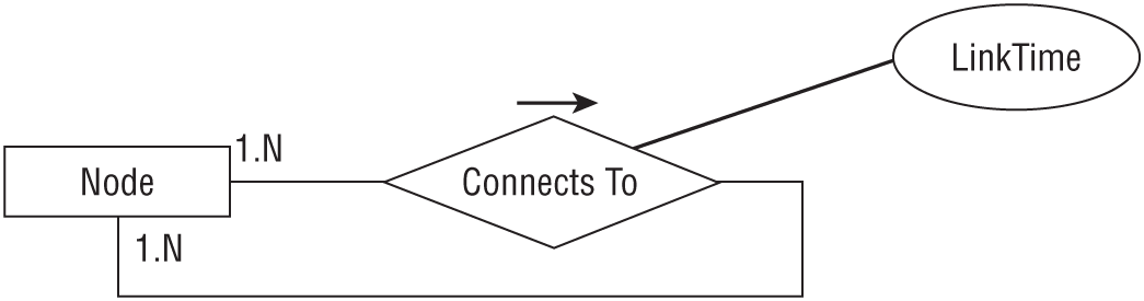
Figure 9.24 shows this design. In addition to a NodeId, the Nodes table contains X- and Y- coordinates for drawing the node.
Note that you need to use some care when you try to use this data to build a network in a program. One natural approach is to start with a node, follow its links to new nodes, and then repeat the process, following those nodes' links. Unfortunately, if the network contains loops, the program will start running around in circles like a dog chasing its tail and it will never finish.
A better approach is to select all of the Nodes records and make program objects to represent them. Then select all of the Links records. For each Links record, find the objects representing the “from” node and the “to” node and connect them. This method is fast, requires only two queries, and best of all, eventually stops.
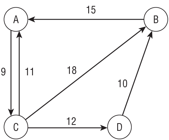
For a concrete example, consider the small network shown in Figure 9.25. As before, the numbers next to links show the links' times.
Start by making a Nodes table with fields NodeId, X, and Y. The following table shows the Nodes table's values. The X and Y fields are blank here because we're not really going to draw the network, but a real program would fill them in.
| NODEID | X | Y |
|---|---|---|
| A | ||
| B | ||
| C | ||
| D |
Next make a Links table with fields FromNode and ToNode, plus a LinkTime field. Look at Figure 9.25 to see which nodes are connected to which others and what their LinkTime values should be. The following table shows the Links table's data.
| FROMNODE | TONODE | LINKTIME |
|---|---|---|
| A | C | 9 |
| B | A | 15 |
| C | A | 11 |
| C | B | 18 |
| C | D | 12 |
| D | B | 10 |
Network Data with NoSQL
Two sections ago, I mentioned NoSQL graph databases. They work well with trees because trees are a special kind of graph. They also work with more general graphs (which are also called networks), and they have the same advantages that they do for trees.
JSON and XML files are naturally hierarchical, so they make storing tree-like data easy. They're not really intended to work with network data, however. In particular, they have trouble with loops in the link data. You can still use them, but you might have to use special tools or do some of the work in your code. You can still store networks in these kinds of files, but it may be easier to use a graph database.
Unless you need relational capabilities, you'll probably get better performance if you store network data in a NoSQL graph database.
TEMPORAL DATA
As its name implies, temporal data involves time. For example, suppose you sell produce and the prices vary greatly from month to month. (For instance, tomatoes are expensive in the winter, while pumpkins are practically worthless on November 1.) To keep a complete record of your sales, you need to track not only orders but also the prices at the time each order was placed.
The following sections describe a few time-related database design issues.
Effective Dates
One simple way to track an object that changes over time is to add fields to the object giving its valid dates. Those fields give the object's effective or valid dates.
Figure 9.26 shows a relational model for temporal produce orders or orders for any other products with prices that change over time.
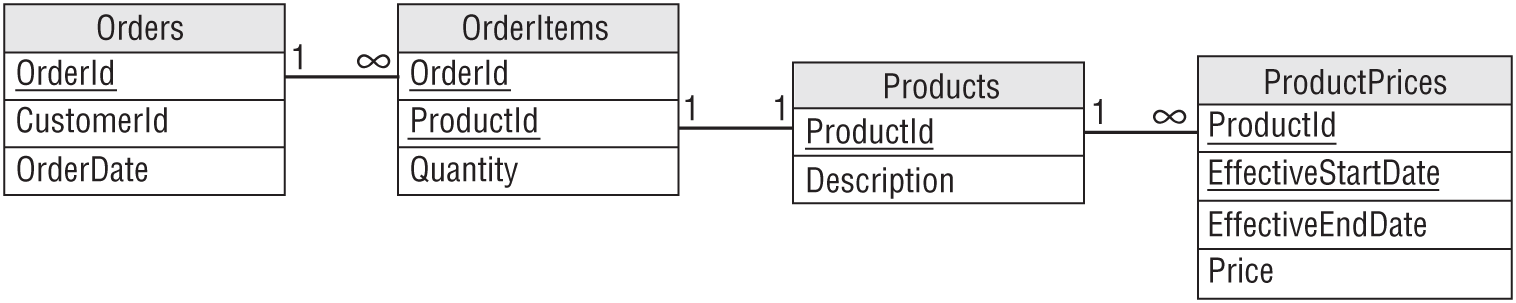
The Orders table contains an OrderId field and a Date, in addition to other order information such as CustomerId. The OrderId field provides the link to the OrderItems table.
Each OrderItems record represents one line item in an order. Its ProductId field provides a link to the Products table, which describes the product purchased on this line item. The Quantity field tells the number of items purchased.
The ProductPrices table has a ProductId field that refers back to the Products table. The Price field gives the product's price. The EffectiveStartDate and EffectiveEndDate fields tell when that price was in effect.
To reproduce an order, you would follow these steps:
- Look up the order in the Orders table and get its OrderId. Record the OrderDate.
- Find the OrderItems records with that OrderId. For each of those records, record the Quantity and ProductId. Then:
- Find the Products record with that ProductId. Use this record to get the item's description.
- Find the ProductPrices record with that ProductId and where EffectiveStartDate ≤ OrderDate ≤ EffectiveEndDate. Use this record to get the item's price at the time the order was placed.
The result is a snapshot of how the order looked at the time it was placed. By digging through all of these tables, you should be able to reproduce every order as it appeared when it was entered into the system.
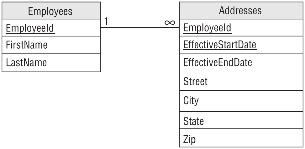
For another example, suppose you want to store one address for each employee but you want to track addresses over time. You don't want to track any other employee data temporally.
To build a relational model to hold this information, start by creating a basic Employees table that holds EmployeeId, FirstName, LastName, and other fields as usual.
Next, design an Addresses table to hold the employee addresses. Create Street, City, State, and Zip fields as usual. Include an EmployeeId field to link back to the Employees record and EffectiveStartDate and EffectiveEndDate fields to track temporal data.
Figure 9.27 shows the resulting relational model.
Deleted Objects
When you delete a record, the information that the record used to hold is gone forever. If you delete an employee's records, you lose all of the information about that employee, including the fact that he was fired for selling your company's secrets to the competition. Because the employee's records were deleted, they could potentially get a job in another part of the company and resume spying with no one the wiser.
Similarly when you modify a record, its previous values are lost. Sometimes that doesn't matter, but other times it might be worthwhile to keep the old values around for historical purposes. For example, it might be nice to know that an employee's salary was increased by only 0.25 percent last year, so you might consider a bigger increase this year.
One way to keep all of this data is to never, ever delete or modify records. Instead, you use effective dates to “end” the old record. If you're modifying the record rather than deleting it, you would then create a new record with effective dates starting now.
For example, suppose you hired Hubert Phreen on 4/1/2027 for a salary of $45,000. On his first anniversary, you increased his salary to $46,000 and on his second you increased it to $53,000. He then grew spoiled and lazy, so he hasn't gotten a raise since. The following table shows the records this scenario would generate in the EmployeeSalaries table. Using this data, you can tell what Hubert's current salary is and what it was at any past point in time.
| EMPLOYEE | SALARY | EFFECTIVESTARTDATE |
|---|---|---|
| Hubert Phreen | $45,000 | 4/1/2027 |
| Hubert Phreen | $46,000 | 4/1/2028 |
| Hubert Phreen | $53,000 | 4/1/2029 |
Deciding What to Temporalize
If you decide to use effective dates instead of deleting or modifying records, then you will end up with a bigger database. Depending on how often these sorts of changes occur, it might be a much bigger database.
Disk space and cloud storage is relatively inexpensive these days (as little as $0.022 or so per GB and dropping every year), so that may not be a big issue. If the database is enormous, however, you may want to be selective in what tables you make temporal.
For example, in the model shown in Figure 9.26, only the ProductPrices table has effective dates. That would make sense for that example if you don't allow changes to orders after they are created. That greatly reduces the amount of data that you will have to duplicate to record changes.
Before you rush out and add effective dates to everything in sight, carefully consider what data is worth saving in this manner. Be sure to decide which tables to make temporal as early as possible because retrofitting effective date fields can be very difficult, particularly for any programs that access the data. Any queries that request data from tables with effective dates must be parameterized to get the right dates. This is definitely a case where you want thorough planning before you start to build.
If the application will generate too much temporal data, then you may want to consider moving older records into long-term storage. You can buy separate hard drives to hold older data and tuck them away somewhere on a less used server. It might take you longer to pull this data back when you need it, but this approach will keep the main database leaner and faster.
If you're using a cloud database, then you can move older data into your provider's long-term storage plans. This typically makes storing data cost less, but you might pay an access fee to retrieve data and there may be minimum duration requirements. For example, to use Google's Nearline storage, you need to keep the data in storage for at least 30 days.
The following table shows approximate prices for Google's cloud storage for a server in Iowa. (I found these prices at https://cloud.google.com/storage/pricing#storage-pricing, but they are subject to change. In fact, they're likely to change before you even see this book. I can't even guarantee that Google won't move that page.)
| PLAN | MINIMUM DURATION | STORAGE PER GB | RETRIEVAL PER GB |
|---|---|---|---|
| Standard | None | $0.0200 | $0.00 |
| Nearline | 30 days | $0.0100 | $0.01 |
| Coldline | 90 days | $0.0040 | $0.02 |
| Archive | 365 days | $0.0012 | $0.05 |
The exact prices depend on many factors such as the frequency of transactions, average availability of the servers in hours per day and days per week, number of CPUs, GPUs, and threads, number of nodes, number of certain kinds of operations, and the data center's physical location. (Presumably the bytes are bigger in Texas and more fashionable in Milan or something.) In general, longer-term plans cost less for storage and more for retrieval. You can do your own calculations to see which plan will be most cost-effective for your scenario.
LOGGING AND LOCKING
Two techniques that I've found useful in a number of database applications are audit trails and turnkey records. Audit trails let you log changes to key pieces of data. Turnkey records let you easily control access to groups of related records.
Audit Trails
Many databases contain sensitive data, and it is important to make sure that the data is safe at all times. While you cannot always prevent a user from incorrectly modifying the data, you can keep track of who made a modification. Later, if it turns out that the change was unauthorized, you can hunt down the perpetrator and wreak a terrible vengeance.
One way to provide a record of significant actions is to make an audit trail table. This table has fields Action, Employee, and Date to record what was done, who did it, and when it happened. For some applications, this information can be nonspecific, for example, recording only that a record was modified and by whom. In other applications, you might want to record the fields that were modified together with the old and new values.
A similar technique works well with the effective dates described in the section “Temporal Data” earlier in this chapter. If you never delete or update records, then you can add a CreatedBy field to a table that you want to audit and fill in the name of the user who created the record. Later, if someone modifies the record, you will be able to see who made the modification in the new version of the record.
You may still want a separate AuditEvents table, however, to record actions other than creating, deleting, and modifying records. For example, you might want to keep track of who views records (as in the State Department passport case), generates or prints reports (so you know that they were printed), sends emails, or prints letters. You might even want to record user log in and log out times depending on your security needs, accountability requirements, and general level of paranoia.
Turnkey Records
When a user needs to modify a record, a relational database locks that record so that other users can't see an inconsistent view of the data. This prevents others from seeing a half-completed operation. (This isn't necessarily true in NoSQL databases, which only guarantee eventual consistency.)
Relational databases also provide transactions that allow one user to perform a series of actions atomically—as if they were a single operation. This effectively locks all the records involved in those actions until the transaction is complete.
These features work well, but their record-locking behaviors can lead to a couple of problems.
First, most databases won't tell you who has a record locked. If someone is in the middle of editing a record in the Employees table, you won't be able to edit that record. Unfortunately, the database won't tell you that Frank has the record locked, so you can't go down the hall and ask him to release it. Or worse, you'll discover that Frank left his computer locked and went home for an early weekend so you're stuck until Monday. In that case, it will require database administrator powers and an act of Congress to unlock the record so you can get some work done.
A second issue is that a complicated series of locks adds to the database's load.
One technique that I've found useful for addressing these problems is to use a turnkey record to control access to a group of tables.
Suppose normalization has spread a work order's data across several tables holding basic information, addresses, phone numbers, email addresses, the actual items ordered, and other stuff. Now, suppose the system is designed to assign work orders to users for processing. It would be nice to lock a work order's data while a user is working on it so others can't blunder in and make conflicting changes. Unfortunately, it's wasteful to lock all of those records.
To use a turnkey record, add a LockedBy field to a table that is central to the work order. This is probably the table that contains the work order's basic information.
Now to “reserve” the work order for use by a particular user, the program sets this record's LockedBy field to the user's name. That token means that this user has permission to mess with all of the work order's records in all of its tables without actually locking anything. Because the user's name is in the database, other parts of the program can tell that the record is locked and by whom. The program can even allow an administrator with appropriate privileges to clear that field so you can fix the work order after Frank has gone home.
The one drawback to this method is that if Frank's computer crashes while he has the work order reserved, then it remains reserved just as if Frank has left for an endless vacation. To recover, you'll need to add an option in the program to clear those sorts of zombie reservations.
A similar technique gives most of the same benefits while removing the problems that come with a LockedBy field. Suppose you assign each work order to a particular person who then works on it, and no one else is allowed to work on that order.
To handle this case, add an AssignedTo field to the order. Some agent (either human or automated) sets the AssignedTo field and after that the field doesn't need to be changed. In that case, if Frank's computer crashes, his record is still assigned to him after he reboots. Because Frank is still the one who should work on the job, you don't need to clear this field. (In practice, however, there will always be a situation where someone needs to foist a job off on someone else for some weird reason, so you should allow some way for an administrator to step in and fix it if necessary.)
SUMMARY
This chapter described some common patterns that you can use to solve particular database design problems. For example, if you need to build a database that includes many-to-many relationships, you can use the pattern described in the section “Many-to-Many Associations” to implement that part of your relational database design.
In this chapter, you learned to model:
- Many-to-many relationships and multiple-object associations
- Repeated attribute associations
- Reflexive or recursive associations
- Temporal data
- Logging and locking
The next chapter does the opposite of this one. It describes common mistakes that people make when designing databases and explains ways to avoid those mistakes.
Before you move on to Chapter 10, however, use the following exercises to test your understanding of the material covered in this chapter. You can find the solutions to these exercises in Appendix A.