
4
![]()
Multibound Solitons
![]()
Le Nguyen Binh
Hua Wei Technologies, European Research Center, Munich, Germany
Nguyen Duc Nhan
Institute of Technology for Posts and Telecommunications, Hanoi, Vietnam
CONTENTS
4.2 Bound Solitons in Passive Mode Locking
4.2.2 Bound States in a Passive Mode-Locked Fiber Ring
4.3 Bound Solitons in Active Mode Locking and Binding Conditions
4.4 Generation of Multibound Solitons in Frequency Modulation Mode-Locked Fiber Laser
4.4.3.1 Formation of Multisoliton Bound States
4.4.3.2 Evolution of the Bound Soliton States in a Frequency Modulation Fiber Loop
4.5 Relative Phase Difference of Multibound Solitons
4.5.1 Interferometer Measurement and Experimental Setup
4.7 Effect of Phase Modulation on Multibinding of Soliton Pulses
4.7.1 Electro-Optic Phase Modulators
4.7.1.2 Traveling-Wave Modulator
4.7.2 Characterization Measurements
4.7.3 Comb Spectrum in Active Fiber Ring Resonator Using Phase Modulator
4.7.3.1 Birefringence and Comb Spectrum in the Fiber Ring Using Phase Modulator
4.7.3.2 Discrete Wavelength Tuning
4.7.4 Influence of Phase Modulator on Multibound Solitons
4.7.4.1 Formation of Multibound Solitons
4.7.4.2 Limitation of Multibound Soliton States
![]()
4.1 Introduction
Optical solitons have attracted considerable attention in research and practical applications on not only their generation techniques but also dynamics. Understanding the dynamics of solotonic waves is of much significance for soliton applications in communications and signal processing. Therefore, extensive studies on soliton interactions must be conducted. For practical dissipative systems such as mode-locked fiber lasers, the interaction between solitons can be theoretically described by the complex Ginzburg–Landau equation (CGLE) instead of the nonlinear Schrödinger equation, which is only valid in conservative systems. Hence, interaction states of solitons based on CGLE have attracted considerable attention in theoretical approaches. Malomed analyzes the interaction of slightly overlapping CGLE solitons and first predicted about the formation of effectively stable dual- and multipulse bound states of solutions [1,2]. Then Akhmediev et al. numerically investigated the interaction of the CGLE solitons by using a two-dimensional (2-D) phase space approach [3]. They also found the stable solution of dual and multipulse bound solitons with a π/2 phase difference between them. These theoretical results opened a new research frontier on the mutual relationship between the states and the dynamics of short pulses in the mode-locked fiber lasers.
It had taken one decade since Malomed’s prediction to experimentally demonstrate the existence of the bound solitons in the passive mode-locked fiber laser using nonlinear polarization rotation (NPR) technique [4]. Then, the bound solitons were also reported in the passive mode-locked fiber laser using a nonlinear fiber loop mirror (NFLM) [5]. Most numerical and experimental investigations on various operational modes and dynamics of bound solitons have been implemented in the passive mode-locked fiber lasers [4–18]. However, the question is whether or not it is possible to generate bound solitons in active mode-locked fiber lasers. Bound soliton pairs, but not multibound solitons, were experimentally observed for the first time in an active frequency modulation (FM) mode-locked fiber laser [19]. Then, multibound solitons with an order higher than two were experimentally demonstrated [20]. In this chapter, we describe the generation and the formation mechanism of multibound solitons from active FM mode-locked fiber lasers. The characteristics of multibound solitons are described and analyzed.
![]()
4.2 Bound Solitons in Passive Mode Locking
4.2.1 Multipulsing Operation
Bound soliton states can be considered as one of the multiple soliton operation modes of the passive mode-locked fiber laser. On the other hand, the formation of bound solitons relates to multipulse operation and effective interactions between solitons inside the fiber cavity. In a strongly nonlinear regime of operation, passive mode-locked fiber lasers exhibit a multipulsing behavior. The existence of multiple solitons in the cavity also refers to the soliton energy quantization effect that limits the peak power of solitons under some specific conditions. Efforts in finding mechanisms of multipulse formation that is important for optimization and design of solution fiber lasers have been achieved [21–23].
There are three main mechanisms of multipulse formation that limit the peak power of the pulse circulating in the cavity. The first mechanism relates to the pulse splitting due to the limited gain bandwidth [22]. Under high nonlinearity due to strong pumping, the mode-locked pulse is compressed by the self-phase modulation (SPM) effect so that its spectrum is broadened so wide that some frequency components can exceed limited bandwidth of the gain medium. Consequently, the pulse experiences higher extra loss of the cavity and splits into two pulses with wider pulse width or smaller spectral width to avoid this loss.
According to the above mechanism, a pulse would experience a compression process until its width is so narrow that it splits into two pulses. In conditions of the fiber laser, however, solutions are considerably chirped by SPM and gain bandwidth limitation effect. A generation of subpulses from an initial pulse can occur during circulating in the high-power cavity because of strong chirping after a number of round-trips [21]. These subpulses can keep growing to have the same width and amplitude. According to dissipative solution theory, this second mechanism of the multipulse generation can also be explained as follows: Due to the dissipative nature of the fiber lasers, the dispersive waves are generated by shedding the energy of the solution during circulating in the cavity. In a strongly pumping gain medium, a part of dispersive waves acquires sufficient gain to grow and evolve into a new dissipative solution with the width and amplitude specified by the fiber cavity parameters [24].
Another mechanism of multipulsing is based on the cavity effect that relates to the transmittance of the cavity formed by NPR or NFLM. As explained in Chapter 3, the transmittance of the fiber cavity in both techniques using NPR and NFLM is a sinusoidal function of the nonlinear phase delay (modulation). Thus, there are two distinct regimes of operation in a period of the transmittance curve (see Figure 3.1). In the first half, the transmittance increases with increasing intensity, while the transmittance decreases with increasing intensity in the second half. The maximum of the transmittance curve is also the transition point between two regimes. For mode locking, the cavity operates in the first regime due to the characteristic of saturable absorption. When the nonlinear phase delay is sufficient in solution operation of the fiber laser, the cavity can be dynamically switched from the saturable absorption mode to the saturable amplification mode that limits the peak of solutions generated inside the cavity. For NPR technique, the switching point between two modes can be adjusted by changing the setting of polarization controllers to change the linear phase delay. As a result of the cavity feedback, the peak power of solution is limited, which is responsible for the multipulse operation in the cavity [25].
4.2.2 Bound States in a Passive Mode-Locked Fiber Ring
Although the multipulsing operation was experimentally observed sometime ago [26], only until 2001 were the bound states of solitons confirmed for the first time in an experiment on soliton formation in a passive mode-locked fiber laser using the nonlinear polarization rotation technique [4]. This observation activated stimulating research interest in new states of solitons in the mode-locked fibers. Grelu et al. also reported the experimental observation of two, three, and multibound solitons with the separation between adjacent pulses varying under different conditions [6,9]. By using a strictly dispersion-managed fiber cavity, multipulse solitons can be formed with a fixed pulse separation [15]. In the bound states, the multipulse bound solitons function as a unit, and they also behave in similar dynamics to a single soliton in the cavity such as forming states of bound multipulse solitons or period-doubling, period-quadrupling, and chaotic states [16]. The investigation of bound solitons was extended in fiber lasers operating in large normal cavity dispersion regimes where the pulse shape is parabolic rather than hyperbolic secant [27]. Bound soliton pairs were also observed in nonlinear optical loop mirror (NOLM) figure-eight fiber lasers under the condition of nonbalancing in the total dispersion [8]. Research efforts on bound solitons have been in progress, and the latest report has shown the observation of the bound state of 350 pulses or a “soliton crystal” in an NPR mode-locked fiber laser, a record in the number of pulses in a bound state [28].
The formation of bound states following the pulse-splitting process in passive mode locking can be affected by various interaction mechanisms among solitons inside the cavity. Depending on the setup of the fiber laser, one or more than one interaction mechanisms become stronger than the others and determine the formation and the dynamics of bound solitons. In passive mode-locked fiber lasers, there are a variety of possible interaction mechanisms that relate to different modes of bound solitons as follows:
• Gain depletion and recovery: The interaction between pulses with the transient depletion and recovery dynamics of the gain medium. The pulses effectively repel each other due to a group velocity drift caused by the time-dependent gain depletion acting in conjunction with the gain recovery. This mechanism is significant in the stabilization of pulse spacing in harmonic mode locking [29].
• Acoustic effect and electrostriction: Due to the intense electric field, the optical pulses can interact with the materials forming the fiber-guided medium to generate acoustic waves in the propagation of the consecutive pulses. This electrostriction induces a small frequency shift between the lightwaves under the pulses leading to effective pulse-to-pulse attraction [30].
• CW component and soliton interaction: In some given settings of the passive mode-locked fiber laser using NPR, a CW component can coexist with the solitons in the cavity. It has been experimentally shown that the CW component causes the central frequency shift in each soliton [12]. When the CW component becomes unstable, the solitons acquire different frequency shifts that result in their various relative velocities in the cavity. This interaction is also responsible for motion mode and harmonic mode locking in passive mode-locked lasers [31].
• Soliton–soliton interaction: This direct interaction between solitons is from the nature of fundamental solitons that can attract or repel each other depending on their relative phases. A repulsive force appears between quadrature solitons, that is when their phase difference is in a multiple number of pi/2, while an attraction occurs when they are in phase. In general, this interaction is considerably effective only when the solitons are sufficiently close together [32].
• Soliton-dispersive wave interaction: During the circulating in the cavity, solitons radiate dispersive waves or continuum due to periodically varying perturbations of the cavity such as losses, bandwidth limited gain [32]. The dispersive waves create a local interaction that can generate an attractive or repulsive force between solitons [33].
When solitons interact together through these mechanisms, different bound states can be formed inside the fiber cavity. Depending on the binding strength between solitons, bound solitons can be classified into two basic types: loosely and tightly bound solitons. For the former type, solitons are often bound together into a bunch with the temporal separation between the pulses much larger than their pulse width. Therefore, the loosely bound solitons have a weak binding energy, and they would be easily destroyed by environmental perturbations. Due to wide separation between solitons, the long-range interactions such as the two first mechanisms play a dominant role in formation of loosely bound solitons. Self-stabilization of this state can be achieved by a balance of the interplay between these mechanisms [34].
For tightly bound solitons, two last mechanisms play a major role in the formation of the bound states. Because solitons in this type are closely separated, local interactions are attributed to the binding energy between individual solitons that determines the characteristics and the dynamics of bound solitons. It has been shown that the direct soliton interaction mainly contributes to the formation of tightly bound solitons with discrete fixed separations [15]. We note that pulses formed in the fiber lasers are often chirped solitons, the direct interaction among them is not like that of nonlinear Schrödinger equation (NLSE) solitons. Therefore, the overlap of oscillating tails of solitons results in an effective binding between them to obtain a stable bound state. However, it was believed that the dispersive wave-soliton interaction also affects the ability to generate various dynamics of bound solitons [35]. Due to strong binding energy, the tightly bound soliton behaves as a unit and exhibits all features of a single soliton pulse such as collision, harmonic mode locking, and evenly bound state.
Summarily, all various interactions among solitons always coexist in a passive mode-locked fiber laser. However, only one or two of them play a key role in the formation and characteristic of bound solitons. Furthermore, the existence of other interactions also contributes to the dynamics of their bound states. In other words, the bound soliton falls into only one of multipulse operations under some specific conditions of the cavity settings.
![]()
4.3 Bound Solitons in Active Mode Locking and Binding Conditions
In active mode locking, although the multipulsing operation is more difficult to achieve than that in passive mode locking due to higher loss of the cavity, it still occurs under strong pumping mode of the gain medium. Mechanisms of pulse splitting in active mode locking are also similar to those for passive mode locking. However, the width of the pulse in active mode locking is much wider than that in the passive mode locking, and the contribution of the limited bandwidth of the gain medium of the peak power limiting effect is negligible, unless when either a band-pass filter is inserted into the ring or an intrinsically filtering effect from the ring cavity sufficiently shortens the gain-bandwidth product. Therefore, splitting of a single pulse into multipulses can only occur in an active fiber cavity when the power in the fiber ring increases above a certain mode-locking threshold. At a higher-power, higher-order solitons can be excited. In addition, the accumulated nonlinear phase shift in the loop must be sufficiently high so that a single pulse can split into many pulses [36]. The number of split pulses depends on the optical power preserved in the ring, so there is a specific range of power for each splitting level. The fluctuation of pulses may occur at a region of power where there is a transition from the lower splitting level to the higher. Moreover, the chirping caused by the phase modulator in the loop also makes the process of pulse conversion from a chirped single pulse into multipulses taking place more easily [37,38]. In hybrid mode-locked fiber lasers using NPR for pulse shaping, the peak power limiting effect is caused by the additive pulse limiting (APL) effect [39]. By a proper setting of the cavity parameters, the cavity can be switched from an additive pulse mode (APM) locking regime to an APL regime that can clamp the peak of solitons at a certain level.
Because the pulse splitting only occurs at some specific positions around the minima of the modulation curve in the cavity, the split pulses are closely separated. The tightly bound states are thus assuming the only mode existed in the active mode-locked fiber lasers. Hence, there are effective interactions among these pulses to stabilize the multibound states in the cavity. In other words, the multibound solitons can be formed and stabilized by a balanced interplay between these interactions. The direct soliton interaction, which is influenced by the relative phase difference of the optical carrier under the envelope of adjacent pulses, is believed to contribute significantly in the formation of bound solitons. However, for an actively FM mode-locked fiber laser, another interaction among these pulses needs to be considered due to the linear chirping effect caused by active phase modulation. Particularly, the multibound soliton sequence is only stably formed at the up-chirping half-cycle for the case of an anomalous path-averaged dispersion fiber ring. On the other hand, the bound soliton pulses should be symmetrically distributed around the extreme of the positive phase modulation half-cycle where the pulses acquire up-chirping as described in Figure 4.1. Thus, the group velocity of the lightwave, induced by anomalous dispersion, contained within the first pulse of the soliton bunch is decreased after passing through the phase modulator, while the last pulse of the bunch receives the opposite effect—enhancement of group velocity. The variation of the group velocity between pulses creates an attractive force that pulls them to the extreme of a modulation half-cycle similar to the jittering control in soliton transmission systems [40]. Thus, another interaction between the solitons is required to balance the effective attraction by linear chirping, and it is the direct soliton interaction. A repulsive force sufficient enough to balance with the effective attractive force appears only in case of the π phase difference between adjacent pulses [41–43]. For other phase differences, there is an energy exchange or an attraction between pulses that are possibly not conforming to the stable existence of multibound pulse sequence in an frequency modulation mode-locked fiber laser (FM-MLFL). Thus, we can generate the multisoliton bound states using an appropriate phase modulation profile that can even be the high-order harmonics of the modulation frequency. When stable pulse sequence is formed, the pulses have traveled at least 500 rounds of the fiber ring. Thus, significant delays occur between the lightwave carriers under the bound soliton pulses. If longer distance is traveled by the pulse sequence, there would be breaking up of the sequence, and any nonlinear phase shifts can push the sequence into chaotic states. Currently it is difficult to compensate for the different delays between the lightwaves contained within the pulses. Therefore, in a specific mode-locked fiber laser setup, beside the optical power level and net dispersion of the fiber cavity, the modulator-induced chirp or the phase modulation index determine not only the pulse width but also the temporal separation of bound-soliton pulses at which the interactive effects cancel each other.

FIGURE 4.1
Effective interactions in multibound solitons: (a) dual-soliton bound state and (b) triple-soliton bound state.
The presence of a phase modulator in the cavity is to balance the effective interactions among bound-soliton pulses, which is similar to the use of this device in a long haul soliton transmission system to reduce the timing jitter [44,45]. For this reason a simple perturbation technique can be applied to determine the role of phase modulation on the formation mechanism of multibound solitons. The optical field of a multisoliton bound state can be described as
![]()
and
![]()
where N is the number of solitons in the bound state; T0 is the pulse width of soliton; and Ai, Ti, θ i, ω i represent the amplitude, position, phase, and frequency of soliton, respectively. In the simplest case of the multisoliton bound state, N is equal to 2 or we consider the dual-soliton bound state with the identical amplitude of pulse and the phase difference of π value (Δθ = θ i+1 – θi =π). The ordinary differential equations for the frequency difference and the pulse separation can be derived by using the perturbation method [44,45]:
![]()
![]()
where β2 is the averaged group-velocity dispersion of the fiber loop, ΔT is temporal separation between two adjacent solitons (Ti+1 – Ti = ΔT) and Lcav is the total length of the ring, m is the phase modulation index, and ωm is the angular modulation frequency. Equation (4.4) shows the evolution of frequency difference and position of bound solitons in the fiber ring in which the first term on the right-hand side represents the accumulated frequency difference of two adjacent pulses during a round-trip of the fiber ring, and the second represents the relative frequency difference of these pulses when passing through the phase modulator. At a steady state, the pulse separation is constant and the induced frequency differences cancel each other. On the other hand, if setting Equation (3.4) to zero, we have
![]()
We can see from (4.5) the effect of phase modulation to the pulse separation, and β2 and αm must have opposite signs, which means that in an anomalous dispersion fiber ring with negative value of β2, the pulses should be up-chirped. With a specific setup of the active FM fiber laser, when the magnitude of chirping increases, the bound pulse separation can decrease subsequently. The pulse width is also reduced according to the increase in the phase modulation index and modulation frequency, so that the ratio ΔT/T0 cannot change substantially. Thus, the binding of solitons in the FM mode-locked fiber laser is assisted by the phase modulation. Bound solitons in the ring experience periodically the frequency shift, and hence their velocity in response to changes in their temporal positions by the interactive forces in the equilibrium state.
In principle, multibound solitons can also be generated in any active mode-locked fiber laser including amplitude mode locking with an appropriate frequency chirping in the cavity. Controllability of linear chirping in the amplitude modulator is required in order to maintain a balance in the steady state. Moreover, a frequency shifting facilitates a pulse splitting due to broadening the pulse spectrum in a limited gain bandwidth [38].
![]()
4.4 Generation of Multibound Solitons in Frequency Modulation Mode-Locked Fiber Laser
4.4.1 Experimental Setup
An active FM-MLFRL has been set up to generate multibound solitons. Initially, we used the experimental setup of the FM mode-locked fiber laser as shown in Figure 4.2a. Because the erbium-doped fiber amplifier (EDFA) in this setup has low gain and saturated power that was insufficient for multipulse operation, two EDFAs with 12 dBm maximum output were used for the experiment of multibound soliton generation. However, this setup was limited in the number of bound solitons due to the limitation of the saturated power of the EDFA. Moreover, the amplification stimulated emission(ASE) noise was enhanced by the presence of two EDFAs in the ring that degraded the performance of the bound solitons. Therefore, we replaced this setup with the setup similar to that in the generation of a single-soliton train as described in Chapter 2. We show again the experimental setup of the active FM mode-locked fiber laser for generation of multibound solitons in Figure 4.2b. In this setup, only one EDFA with higher gain and maximum saturated power of 17 dBm is used. The modulation frequency of about 1 GHz is selected to generate the bound solitons. The output is characterized by the instruments in Chapter 2 to estimate the performance of the pulse train.
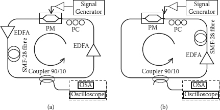
FIGURE 4.2
The experimental setups for multibound soliton generation (a) using two EDFAs with low gain and saturated power and (b) using one EDFA with high gain and saturated power.
4.4.2 Results and Discussion
In our initial setup, the generation of multibound solitons in the active MLFL was achieved [46], yet the number of bound solitons was limited up to the quadruple state due to the limitation of the saturated power of the EDFA. We then extended the experimental investigation with the bound states of up to the sixth order by adjusting the polarization states in association with the total circulating optical power in the cavity. The multisoliton bound states are depicted in Figure 4.3. When the average optical power is sufficiently increased to a certain level, the dual bound states are correspondingly switched to higher-order states. A slight adjustment of the polarization controller is necessary to stabilize the bound states. Figures 4.3a through 4.3e show the traces and spectra of the lowest- to highest-order bound states, the sextuple-soliton bound state, as observed in our experiment. The significant advantage of the active fiber laser is the ease of generation of multisoliton bound sequence at moderately high modulation frequency as shown in the inset of Figure 4.3c1).


FIGURE 4.3
Time-domain oscilloscope traces (1) and optical spectra (2) of (a) dual-soliton, (b) triple-soliton, (c) quadruple-soliton, (d) quintuple-soliton, and (e) sextuple-soliton bound states.
In the tightly bound states, solitons are closely separated, and then the overlap between solitons causes their spectra modulated with the shape and the symmetry depending on their relative phase difference. Hence the existence of the bound states is also confirmed through the shapes of modulated optical spectra as compared to the conventional spectrum of the single soliton state. When the multibound states appear after the optical power in the cavity is increased to an appropriate level, there is a sudden change of the optical spectrum. The symmetry of spectra in Figures 4.3a2 through 4.3e2 indicates a relative phase difference of π between two adjacent bound solitons. The dashed-dot lines show the envelope of modulated spectra that correspond to the spectrum of a single soliton pulse. The suppression of the carrier at the center of the pass-band spectrum further confirms the π phase difference between adjacent pulses, especially the pair of dual-bound solitons. The distance between the two spectral main lobes is exactly correlated to the temporal separation between two adjacent pulses in the time domain. The specific shape of the spectrum depends on the number of solitons in the bound states, which can be odd or even. In the case of even-soliton bound states, such as dual-soliton and quadruple-soliton bound states, there is always a dip at the center of the spectrum, while there is a small hump in the case of the odd-soliton bound state, such as the triple-soliton bound state and quintuple-soliton bound state. The small hump at the center of the spectrum is formed by the far interaction between the next neighboring pulses that are in-phase in bound states. This is similar to the case for the quadrature phase shift keying modulation format, which is well known in the field of digital communications [47]. When the phase difference moves away from the π value, the modulation and symmetry of spectrum vary accordingly. For the sextuple-soliton bound state, its spectrum is weakly modulated due to the variation of phase difference induced by enhanced ASE noise. The change in relative phase locking influences the interaction of adjacent pulses or the performance of bound soliton output as in Figure 4.3e.

FIGURE 4.4
The variation of parameters with the number of solitons in bound states: (a) pulsewidth and temporal separation, (b) ratio between pulsewidth and separation, (c) peak power, and (d) corresponding average power of the cavity.
All important parameters of the multibound solitons experimentally measured are summarized in Figure 4.4 that plots the average values of the pulse width and the time separation between pulses (Δτ), the maximum peak power of a soliton pulse (P0), and average optical power inside the fiber ring against the number of bound solitons. Figure 4.4a shows the variation of the pulsewidth decreasing with respect to the increase in the number of pulses in bound states. This is due to the pulse compression effect, the self-phase modulation, enhanced by the higher optical power level in the cavity at higher-order bound states. The temporal separation between pulses in the multibound state also accordingly decreases to remain a ratio between separation and pulsewidth that is nearly unchanged, which is approximately three as shown in Figure 4.4b. The onset power level of the energy stored in the ring is 7.5, 12, 17, 30, and 40 mW for the generation of dual, triple, quadruple, quintuple, and sextuple states, respectively.

FIGURE 4.5
Time traces of dual-bound solitons in rational harmonic mode-locking schemes: (a) the second-order rational harmonic and (b) the third-order rational harmonic.
Similar to the single-soliton state, the multibound solitons can be generated in rational harmonic mode locking. Figure 4.5 shows the time traces of dual- and triple-bound solitons at the second and third rational harmonic mode locking after increasing properly the intracavity saturated power as well as the radio-frequency (RF) input power to enhance the second harmonic of modulation frequency. With an appropriate phase modulation profile formed by the detuning amount of ± fc / 2, the multibound solitons in rational harmonic mode locking are generated in the same interaction mechanism with the same characteristics as those in the conventional harmonic mode locking. However, the temporal separation between solitons in this case is smaller than that in conventional harmonic mode locking due to the higher chirp rate of higher-order harmonics of modulation frequency. Thus, the multibound solitons can exist in various regimes of operation similar to the conventional single-pulse mode.

FIGURE 4.6
The radio-frequency (RF) spectra of (a) the dual-bound soliton and (b) the quadruple-bound soliton in the span of 10 MHz. (Inset: The RF spectra with high resolution in span of 10 kHz.)
When the higher-order bound solitons operate at a higher power level, they are more sensitive to the change in the polarization state and an even multiwavelength operation can occur. This effect is disadvantageous to the multibound soliton operation due to the reduction of energy of the operating wavelength from other excited wavelengths. On the other hand, higher-order bound solitons are more sensitive to fluctuations of the environmental condition. In experimental conditions, these polarization effects are usually controlled by a polarization controller, especially at the input of an integrated optical modulator so only one polarized state can be preferred through the modulator and hence the forcing of the matching condition of this polarized state. Moreover, the increase in saturated power in the fiber cavity allows generation of higher-order bound soliton states, yet the ASE noise is also enhanced under a strong pumping scheme in the EDFAs. If the phase noise induced by ASE noise is sufficient, it affects not only the phase matching conditions of the fiber ring but also the phase locking between adjacent pulses as discussed above. Figure 4.6 shows the RF spectra of the dual- and quadruple-bound soliton trains to estimate the stability of the multibound soliton train. From the results of RF spectrum analysis, the sideband to carrier ratio (SCR) is higher 45 dB for the dual-bound soliton, but it is reduced to 40 dB for the quadruple-bound soliton. Obviously, there are more fluctuations in higher-order bound states or they are more sensitive to the environmental conditions. However, there are small fluctuations in amplitude and temporal position of solitons in bound states as indicated by a broadening of the spectral line in insets of Figure 4.6. In the experiment, it has been found that the tuning of the polarization controller becomes harder to obtain a stable bound state when the number of solitons in the bound state is larger.

FIGURE 4.7
Time traces of the noise-like pulse at the optical power levels of (a) quadruple-bound and (b) quintuple-bound solitons, respectively.

FIGURE 4.8
Variation of time-separation of dual and triple bound soliton states with respect to the phase modulation index.
Although the electro-optic (EO) phase modulator plays a key role as a mode locker in our active mode-locked fiber laser, we should note that the polarization effect shows an important influence on multibound solitons. At high-power levels of the cavity, the polarization-dependent mechanisms such as polarization-dependent loss (PDL) and polarization-dependent gain (PDG) are enhanced due to the phase modulator also being a polarizing element [48–51]. Hence, the variation of the polarization state changes the total loss or the gain of the cavity that affects the shaping, the formation, as well as the parameters of multibound solitons. We have found that a stable multibound state is only obtained by proper polarization settings. If changing the setting of the polarization controller, beside the stable multibound states observed above, a noise-like pulse regime has been obtained. Figure 4.7 shows the time traces of the noise-like “square” pulses at the power levels of the quadruple- and quintuple-bound solitons, respectively. Although the pulses cannot be resolved in the traces, the widths of these pulses are exactly the same width of the bunch of corresponding bound solitons. This regime seems to be a multipulsing operation but is unstable. Optical spectra of these states are slightly modulated and varied similar to Figure 4.3e2. The pulses in the bunch, which might be in phase, move and even collide together or oscillate very fast around the extreme of the modulation cycle. As a result the pulses cannot be clearly isolated in the bunch. Therefore, the traces of these states on oscilloscope are seen like noisy waveforms.
Different from passive mode-locked fiber lasers, the active phase modulation contributes significantly to the formation and the stability of multibound soliton states. Figure 4.8 shows experimental results of the influence of chirping, which is directly proportional to the phase modulation index, on temporal separation between adjacent pulses at different bound states. When the chirp rate increases, the relative variation of group velocity between adjacent pulses is enhanced. Thus, the increase in frequency chirping reduces the temporal separation necessary to keep the frequency shift between these pulses unchanged in the cavity with a specific average dispersion. The decrease in the time separation in experimental results shows a nearly linear function of the phase modulation index that should be an exponential function as theoretically analyzed in [46]. This can be due to the small range of the phase modulation index. In addition, because the pulse width of the triple-bound soliton is narrower than that of the dual-bound soliton, the pulses acquire a smaller chirp that results in the lower rate of decrease in the time separation in the triple-bound soliton as seen in Figure 4.8.
4.4.3 Simulation
4.4.3.1 Formation of Multisoliton Bound States
To understand the operation of multibound solitons in the active FM mode-locked fiber laser, we numerically investigated the process of multibound soliton generation in the FM mode-locked fiber ring laser by using the numerical simulation model described in Chapter 2 for the active FM mode-locked fiber laser. First, we simulated the formation process of bound states in the FM mode-locked fiber laser whose main parameters are shown in Table 4.1. The lengths of the active fiber and passive fiber are chosen to get the cavity’s average dispersion = –10.7 ps2/km. Figure 4.9 shows a simulated dual-soliton bound state building up from initial Gaussian-distributed noise as an input seed over the first 2000 round-trips with the Psat value of 8 dBm and g0 of 0.36 m–1. The built-up pulse experiences transitions with large fluctuations of intensity, position, and pulse width during the first 1000 round-trips before formation of the bound soliton state. Figures 4.9b and 4.9c show the time waveform and spectrum of the output signal at the 2000th round-trip.
TABLE 4.1
Simulation Parameters of the Multibound Soliton Formation
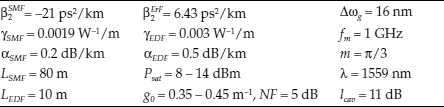

FIGURE 4.9
(a) Numerically simulated evolution of the dual-soliton bound state formation from noise, (b) the waveform, (c) the spectrum, and (d) the phase at the 2000th round-trip.
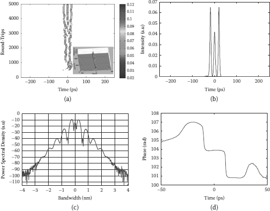
FIGURE 4.10
(a) Numerically simulated evolution of the triple-soliton bound state formation from noise, (b) the waveform, (c) the spectrum, and (d) the phase at the 5000th round-trip.
The bound states with a higher number of pulses can be formed at a higher gain of the cavity; hence, when the Psat and gain g0 are increased to 11 dBm and 0.38 m–1, respectively, which is enhancing the average optical power in the ring, the triple-soliton bound steady state is formed from the noise seeded via simulation as shown in Figure 4.10. In the case of higher optical power, the fluctuation of the signal at initial transitions is stronger, and it needs more round-trips to reach a more stable triple-bound state. The waveform and spectrum of the output signal from the FM mode-locked fiber laser at the 5000th round-trip are shown in Figures 4.10b and 4.10c, respectively.
Although the amplitude of pulses is not equal indicating the bound state can require a larger number of round-trips before the effects in the ring balance, the phase difference of pulses accumulated during circulating in the fiber loop is approximately of π value, which is indicated by strongly modulated spectra. In particular from the simulation result, the phase difference between adjacent pulses is 0.98π in case of the dual-pulse bound state and 0.89π in case of the triple-pulse bound state. These simulation results reproduce the experimental results (shown in Figure 4.9d and Figure 4.10d) discussed above to confirm the existence of multisoliton bound states in an FM mode-locked fiber laser.
FIGURE 4.11
(a) Contour plot of simulated evolution of the dual-soliton bound state formation from noise, and (b) variation of the peak power with the gain switching at the 2000th round-trip, (c) the waveform (Inset: the corresponding spectrum), and (d) the phase at the 10,000th round-trip.

FIGURE 4.12
(a) Contour plot of simulated evolution of the triple-soliton bound state formation from noise, and (b) variation of the peak power with the gain switching at the 2000th round-trip, (c) the waveform (Inset: the corresponding spectrum), and (d) the phase at the 10,000th round-trip.
It is realized that the cavity requires a higher gain to form the multibound states than that in stable or steady states. By adjusting the parameters of gain medium after multipulse state formed in the cavity, stable multibound soliton states can be generated after at least 10,000 round-trips. Figure 4.10a shows the contour of the dual-bound soliton formation in 10,000 round-trips of the ring cavity. In this simulation, the gain factor is reduced from 0.37 m–1 to 0.35 m–1 at the 2000th round-trip (the dash line). In the first 2000 round-trips, the dual-bound soliton is formed, yet unstable with strong fluctuation of the peak power. Then the fluctuation is reduced by the reduction of gain factor, and the generated dual-bound soliton converges to a stable state after 10,000 round-trips as shown in Figure 4.10b. Figures 4.10c and 4.10d show the waveform and the phase of the output at the 10,000th round-trip. Similarly, the parameters of gain medium are also adjusted to a obtain stable higher-order multibound solitons. Figures 4.11 and 4.12 show the simulated results of the triple-bound soliton and the quadruple-bound soliton formation processes, respectively. For the triple-bound soliton, the gain factors are the same values as those in the case of the dual-bound soliton, but the saturated power Psat is increased to 11 dBm instead of 8 dBm. Variation of peak power and evolution of the triple-bound soliton formation with the gain switching at the 2000th round-trip are shown in Figures 4.12a and 4.12b. For the quadruple-bound soliton, both the initial gain and adjusted gain factors are increased to higher values that are 0.4 m–1 and 0.377 m–1, respectively, at the Psat of 11 dBm. Figure 4.12b shows a damping of the peak power variation after the gain adjustment to reach to a stable triple-bound soliton state; however, the peak power of the quadruple-bound soliton still oscillates evenly after 10,000 round-trips as seen in Figure 4.13b. Thus, it indicates more sensitivity of the higher-order multibound soliton to the operating condition. The sensitivity also exhibits through the uniform of pulse intensity in the bound state and the relative phase difference that is decreased from π in the dual-bound soliton to 0.87π in the quadruple-bound soliton as shown in Figures 4.11c and 4.11d, Figures 4.12c and 4.12d, and Figures 4.13c and 4.13d.
We note that a stable multibound soliton is difficult to be formed in the cavity without the adjustment of the gain parameters. With the high gain, the multibound soliton can be generated but unstable or becomes quasi-stable with a periodic variation of soliton parameters in the bound state. With the low gain, the nonlinear phase shift is not sufficient to generate a desirable higher-order multipulse state, while it is too strong for the stable lower-order multibound state. Different from passive mode locking, the pulse splitting in our system is caused by the excitation of higher-order soliton and nonlinear chirping rather than an energy quantization mechanism.

FIGURE 4.13
(a) Contour plot of simulated evolution of the quadruple-soliton bound state formation from noise. (b) Variation of the peak power with the gain switching at the 3000th round-trip. (c) The waveform (Inset: the corresponding spectrum). (d) The phase at the 10,000th round-trip.
4.4.3.2 Evolution of the Bound Soliton States in a Frequency Modulation Fiber Loop
Obviously, a multibound soliton can be stably generated in the phase-modulated fiber cavity. On the other hand, the bound soliton with the relative difference of π given by (4.1) and (4.2) is considered as a stable solution of the active FM mode-locked fiber laser. By using the multisoliton waveform in (4.1) and (4.2) as input, we have simulated the stability of multibound solitons in the active FM mode-locked fiber laser. Figure 4.14 shows the evolutions in 2000 round-trips of the dual- and triple-bound solitons in the cavity. Because the bound solitons are really chirped pulses, while the input in simulation is unchirped, there is a damping oscillation of bound solitons in the initial stage that is considered as a transition of solitons to adjust their own parameters to match the parameters of the cavity. However, the multibound solitons easily reach stable states after only a few hundreds of round-trips.

FIGURE 4.14
Evolution of (a) dual-bound soliton and (b) triple-bound soliton with a relative phase difference of π in the frequency modulation fiber ring cavity.
Simulation results on parameters of multibound solitons after 5000 round-trips are also shown in Figure 4.4 for comparison by using the experimental parameters of multibound solitons as the initial parameters. Generally, the simulated results agree with the experimental results. However, as observed in Figures 4.4c and 4.4d, there are discrepancies of the peak and average power levels between the simulated and experimental pulses, especially at higher-order soliton bound states. The level of discrepancy varies from 0.1 dB to 3 dB for the peak power of 1000 to 1800 mW, respectively. While the experimental results show a nearly linear dependence of the peak power on the order of the bound state, the simulation results show an exponential variation. Hence, there is also a difference of average power of the cavity between them. However, both sets of results indicate an exponential dependence of the cavity average power on the order of the bound soliton state. There are some reasons for taking into account the discrepancy as follows: First, the parameters of the fiber cavity used in the simulation are not totally matched to those in our experiment; second, when the real pulse width at a higher-order bound soliton state is narrower, the accuracy in the pulse width measured on the oscilloscope is reduced, although the influence of rise-time of the oscilloscope was considered in estimation. Furthermore, the variation of the polarization state becomes stronger at a higher power level of the cavity, which also increases the error in the power measurement. Hence, the error between simulation and experimental results increases at a higher order of the soliton bound state. In addition, the higher-order multibound soliton is more sensitive to the cavity parameter settings. Figure 4.15a shows an unstable state evolving in the FM fiber ring cavity. Multiple pulses are generated in the cavity, yet it is difficult to acquire the phase difference of π and uniform between pulses. The balance in the effective interaction between pulses is difficult to be achieved; the pulses can therefore collide and vary rapidly in both amplitude and time position. However, this rapid variation only occurs in a limited time window around the extreme of the modulation cycle as indicated by the dashed lines in Figure 4.15b. By taking an average over the last 2000 round-trips, the waveform and its spectrum, which can be represented for a dynamical state, are shown in Figures 4.15c and 4.15d, respectively. The waveform, which is like a noisy pulse, and the spectrum, which is slightly modulated, are similar to what is observed in the experiment (see Figure 4.7).

FIGURE 4.15
(a) Simulated evolution of multibound soliton in unstable condition over 5000 round-trips. (b) Contour plot view of the evolution. (c) The waveform, and (d) corresponding spectra averaged over last 2000 round-trips.
![]()
4.5 Relative Phase Difference of Multibound Solitons
4.5.1 Interferometer Measurement and Experimental Setup
The relative phase difference plays a key factor in stability as well as the determination of various modes of the bound soliton states. For passive mode locking, although the relative phase between the bound solitons of π has been confirmed in some experimental works [8,11], other relative phases have also been demonstrated [6,8,10]. The relative phase difference is of importance in the determination of dynamics of the bound solitons in the fiber laser system. In particular, the bound solitons with a π/2 phase difference can collide either elastically or inelastically with a single soliton depending on its initial phase [9]. On the other hand, the bound solitons can change their relative phase when the setting of the cavity changes.

FIGURE 4.16
Descriptions of two possibilities of phase difference between neighboring pulses. (a) Solitons between neighboring bunches are in phase. (b) Solitons between neighboring bunches are out of phase.

FIGURE 4.17
Experimental setup and principle of the interferometer measurement.
Different from passive mode locking, only the bound solitons with a π phase difference are stably generated in the active mode-locked fiber laser system, which has been confirmed by their symmetrically modulated spectra. In each bunch of bound solitons, adjacent pulses are out of phase to form a stable bound state through the balanced interplay of effective interactions. However, if the multibound soliton is considered as a unit like the single pulse state, there might be two possibilities of the multibound soliton trains: one in which solitons between neighboring bunches are in phase and another in which solitons between neighboring bunches are out of phase as described in Figure 4.16. On the other hand, there may be a phase inversion between bunches of bound solitons. To check the dynamics of the relative phase difference in a multibound soliton train, which is impossible to be identified through the optical spectrum measurement, an interferometer measurement has been proposed and implemented. Figure 4.17 shows the schematic of the measurement based on an asymmetrical Mach–Zehnder fiber interferometer (MZI). The intensities of the interference patterns at two output ports of the asymmetrical MZI can be given by
![]()
![]()
where Ein is the input field of the MZI, which is the field of the multibound soliton train, and Td is the variable time delay between two arms. Depending on adjustment of the time delay, the pulses of two multibound solitons on two arms would be interfered constructively or destructively over the overlapped positions at the output coupler.
Thus, if there is no dynamic phase inversion between bunches of bound solitons or the phase difference of ±π between multibound solitons remains unchanged, the interference patterns of two outputs would be fixed and contrary to each other when the multibound solitons between two arms are overlapped over one or two pulses. In case of the triple-bound solitons as an example, the calculated patterns of constructive and destructive interferences with two overlapped pulses at the outputs are shown in Figure 4.18. On the contrary, the interference patterns are dynamically varied between two output ports depending on the phase states of multibound solitons between two arms.
In the experimental setup as shown in Figure 4.17, the asymmetric fiber interferometer is built by two 3 dB couplers connected together by optical fibers to form two arms of MZI. A tunable delay line of 80 ps delay time is inserted into an arm of MZI to sufficiently provide an overlapping of multibound solitons (MBS) between two arms at the output coupler. The amplitude of overlapped pulses at the output ports (1’and 2’) of MZI depends on the phase difference of solitons in bound states. This determines either constructive or destructive interferences in the time domain at overlapped positions. The interference patterns at two output ports are simultaneously monitored by two ports on the high-speed oscilloscope.

FIGURE 4.18
Calculated patterns of the triple-bound solitons overlapped over two pulses at two outputs of Mach–Zehnder fiber interferometer. (a) Constructive interference. (b) Destructive interference.
4.5.2 Results and Discussion
The initial phase delay between two arms of the MZI is adjusted by the fiber length difference between two arms. To put it another way, the time difference between multibound solitons in two arms is initially about 75 ps as shown in Figure 4.19a. By adjusting the tunable delay line, a specific overlapping between two triple-bound solitons can be achieved. Figures 4.19b and 4.19c show, as an example, the interference patterns of triple-bound soliton state over two overlapped pulses at ports 1’ and 2’, respectively. The results also indicate that the practical value of phase difference is not equal to π due to the peak power of overlapped pulses at port 1’ and port 2’, which is only three times higher and lower than that of input pulses, respectively. However, the interference patterns are not steady but alternatively changed between two ports. The alternating change of the patterns between two ports indicates that a phase inversion periodically occurs. For a single-pulse scheme in active mode locking, only the pulse train with neighboring pulses out of phase is stable in the cavity [52]. Therefore, in multibound states, it is understandable when solitons are out of phase not only in the bunch but also between the bunches. Because there is a phase shift in each round-trip that is accumulated during circulation in the cavity, the phase inversion occurs after the accumulated phase shift is an integer multiple of 2π. This is also confirmed by simulation results as shown in Figure 4.20 to indicate a periodic variation of the phase difference between –π and π.

FIGURE 4.19
The time traces of triple-bound solitons (a) before overlapped, (b) overlapped at port 1’, and (c) overlapped at port 2’ of the Mach–Zehnder fiber interferometer.

FIGURE 4.20
Periodic variation of the phase difference of a triple-bound soliton over 200 round-trips that is simulated in Figure 4.14b.
![]()
4.6 Remarks
In the above sections, we reviewed the important mechanisms as well as interactions in bound soliton formation of mode-locked fiber lasers. Formation of multibound solitons in active mode locking has also been explained to show the role of phase modulation in the balanced interplay between interactions of multibound solitons.
The generation of stable multisoliton bound states in an FM mode-locked fiber laser has been experimentally and numerically demonstrated. We demonstrated that it is possible to generate the bound states from dual to sextuple states provided that there is sufficient optical energy circulating in the fiber ring. Multibound soliton states in a phase-modulated fiber ring are rigorously explained based on the phase matching and chirping effects of the lightwave and the velocity variation of the optical pulses in a dispersive fiber ring. Experimental and numerical results have confirmed the stable existence of multibound solitons with a phase difference of ±π between neighboring solitons. However, it is more sensitive to the cavity settings as well as the external perturbations at the higher-order multibound soliton states.
![]()
4.7 Effect of Phase Modulation on Multibinding of Soliton Pulses
4.7.1 Electro-Optic Phase Modulators
The integrated-optic modulators including the electro-optic (EO) phase modulators have become essential components in optical transmission systems and photonic signal processing because of their advantages, such as small size and compatibility with a single-mode optical fiber [53]. For an active mode-locked fiber laser, an EO phase modulator acts as a mode-locker, hence its characteristics significantly influence the performance as well as the operation modes of the fiber cavity. In our experimental platform we used two models of integrated EO phase modulators: one is the model PM-315P of Crystal Technology of Sunnyvale, California, United States and another is the model Mach-427 of Covega of Jessup, Maryland, United States. Depending on the geometry of the electrodes, an integrated LiNbO3 modulator can belong to one of two types: lumped-type modulator or traveling-wave-type modulator.
4.7.1.1 Lumped-Type Modulator
A LiNbO3 phase modulator consists of a titanium-diffused mono-mode waveguide and a pair of oriented electrodes. Titanium waveguides can support both transverse electric (TE) and transverse magnetic (TM) optical polarizations. Due to the crystal symmetry in LiNbO3, there are two useful crystal orientations, Z-cut and X-cut, which take advantage of the strongest EO coefficient. For an X-cut device, the waveguide is symmetrically located between two electrodes as shown in Figure 4.21. In a Z-cut device with the optical axis perpendicular to the surface, one of the electrodes is directly placed on the waveguide, and an optical isolation layer is inserted between the waveguide and the electrode to avoid increased optical losses. Application of the electrical driving voltage to the electrodes causes a small change in the refractive index of the waveguide, and the phase of the optical signal passing through the modulator can be consequently changed as
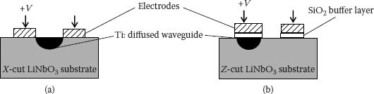
FIGURE 4.21
Geometry of LiNbO3 phase modulators: (a) X-cut and (b) Z-cut orientation substrates.
![]()
where V is the applied voltage, L is the length of the electrode, λ is the wavelength, reff is the appropriate electro-optic coefficient, neff is the unperturbed refractive index, d is the separation between electrodes, and Γ is the overlap factor between the electric field and the optical mode field, which is an important parameter to optimize the modulator design.
Depending on the type of electrode, the EO phase modulators can be classified into two types: the lumped-type modulator and the traveling-wave modulator. A lumped-type EO phase modulator is illustrated in Figure 4.22. In this configuration, the RF driving voltage is directly fed to the electrodes whose lengths are small compared to the drive-signal wavelength, and the modulation bandwidth is limited by the RC time constant of the electrode capacitance (C) and the parallel matching resistance (R) as follows:

FIGURE 4.22
Two types of electro-optic phase modulator: (a) lumped-type, (b) traveling-wave type.
![]()
The matching resistance is normally set to 50 Ω to allow broadband matching to a 50 Ω driving source. For low operating voltage, the modulator of longer interactive lengths is required, but the capacitance of the electrode increases, which limits the maximum frequency of operation. It is difficult to fabricate a lumped-type EO phase modulator with a broad bandwidth and low operating voltage. Lumped-type EO phase modulators can operate at a frequency of a few GHz with the expense of low Vπ.
4.7.1.2 Traveling-Wave Modulator
In order to increase the modulation bandwidth, traveling-wave electrodes are preferably used in the modulator design. Traveling-wave electrodes are designed as transmission lines, fed at one end, and terminated with a resistive load at the other end as shown in Figure 4.22b. The optical signal in the waveguide and the electrical signal in the electrode propagate in the same direction. Because the effective refractive index of the electrical wave nm is about twice that of the optical wave no, there is a velocity mismatch between the electrical wave and the optical wave that limits the modulation bandwidth as follows:
![]()
where c is the velocity of light in a vacuum, and L is the length of the electrode.
Much effort has been put into designing traveling-wave modulators to match the velocities of the electrical and optical waves, and thus to improve the frequency response characteristics. To obtain the velocity matching, the effective index of the electric wave nm is lowered by using effectively a dielectric buffer layer between the electrode and the waveguide. Based on this concept, many structures of the traveling-wave electrode have been proposed to produce the EO modulators with a broad bandwidth of tens GHz and low Vπ [54–56].
4.7.2 Characterization Measurements
4.7.2.1 Half-Wave Voltage
In some options for half-wave voltage (Vπ) measurement, the direct optical spectrum analysis offers an accurate and simple solution in case the modulation sidebands can be resolved by the optical spectrum analyzer (OSA). When a CW light passes through a phase modulator, its spectrum is broadened by generation of modulation sidebands. The strength of sidebands is proportional to the modulation index and the sideband positions. An optical field in the frequency domain of a phase-modulated CW signal can be mathe-matically expressed by Fourier expansion as
![]()
where ω0, ωm are the carrier frequency and RF modulation frequency, respectively; ; k is the sidemode index that is an integer; Jk is the kth-order Bessel function of first kind; and Eo, Ei are the output and input fields of the phase modulator, respectively. Thus, the intensity of each sidemode measured on an OSA is
![]()
where m is the modulation index and related to the Vπ by (4.8) and. Expression (4.12) shows a relationship between the modulation index and the intensity at a specific sideband that varies as a Bessel function as shown in Figure 4.23. Based on optical spectrum analysis, there are some approaches for the Vπ measurement such as the carrier nulling method [57] and the relative sideband/carrier intensity ratio method [58]. In the power limitation of RF amplifiers, the relative first sideband/carrier intensity ratio is the most suitable method for small signal modulation that is used for our measurement.
The measurement setup and the components are depicted in Figure 4.24. The phase modulators consisting of the model PM-315P and the model Mach427 Covega were characterized by OSA at a modulation frequency of 1 GHz. For a conventional OSA, the resolution is limited to resolve the modulation sidemodes at such a low frequency. Fortunately, we borrowed a high-resolution spectrum analyzer Agilent 83453B for this measurement. By the OSA with resolution of <0.008 pm (~1 MHz), the intensity of sidemodes with spacing of 1 GHz can be clearly displayed as shown in Figure 4.25. At a specific RF driving power the modulation index m is calculated from the relative intensity ratio between the carrier and the first sidemode R1,0:

FIGURE 4.23
Variation of (a) normalized optical intensity for carrier and sidemodes, and (b) ratio R1,0 as a function of phase modulation index m.

FIGURE 4.24
The OSA-based Vπ measurement setup.
![]()
which is measured by the OSA. By varying the RF driving voltages, the Vπ of two phase modulators can then be determined from the slope of the linear fit line as shown in Figure 4.26. The estimated Vπ of PM-315 and Mach427 are 3.93 V and 8.87 V, respectively. These results agree with the specifications provided by producers.
4.7.2.2 Dynamic Response
The dynamic response of the EO phase modulator is an important characteristic that indicates the variation of modulation efficiency over a range of frequencies. Because optical phase modulators only modulate the phase of the optical carrier, it is impossible to measure directly the modulator response. A conversion of phase modulation into amplitude modulation needs to be done for this measurement. Several techniques were proposed to implement this operation consisting of using a Mach–Zehnder interferometer [57], using a Fabry–Perot interferometer as an optical discriminator [59], and using a Sagnac loop configuration [60]. However, two former techniques are limited in use due to their complexity and reliability, the last technique provides an efficient and simple way of measuring the dynamic response for all types of EO phase modulators with high resolution. Especially, various types of the phase modulator can be identified through this measurement.

FIGURE 4.25
Optical spectra of the signal modulated by phase modulators: (a) PM-315P, (b) Mach-427 at the same radio-frequency driving level of 19 dBm.

FIGURE 4.26
Phase modulation index calculated from measured relative intensity ratio R1,0 at 1 GHz as a function of radio-frequency driving voltage for two models: (a) PM-315P and (b) Mach-427.
The setup of the dynamic response measurement based on a Sagnac loop is shown in Figure 4.27. This configuration is similar to the configuration of phase modulation Sagnac loop (PMSL) described in Chapter 2. The only main difference is the position of the phase modulator in the Sagnac loop that is off-centered. Two counterpropagating optical waves are phase modulated and then coherently summed at the output 3 dB coupler. This process converts phase modulation into intensity modulation, so that the response of the phase modulator can be measured by a network analyzer HP8753D and an S-parameter test set HP85046A. The polarization is optimized by the polarization controller to maximize the optical power passing through the lithium niobate optical waveguide. Thus, the transfer function for this structure, which can be detected by the network analyzer, is given by [60]

FIGURE 4.27
The measurement setup of the dynamic response.
![]()
where lPM is the insertion loss of phase modulator, K0(f) is the modulation response parameter, R0 is the load resistance, ℜ is the detector responsivity, ϕ(f) is the phase difference, and η(f) is the ratio of backward-to-forward phase modulation index that relates to the signal transit time tL [61] as follows:
![]()
This structure is also a notch filter applied in photonic signal processing [62], so that the dynamic response of the phase modulator should be the envelope of the periodic notch filter response. The free spectral range (FSR) of the notch response relates to the phase difference by
![]()
where τ, ΔL are the time delay and the length difference between two sides of the Sagnac loop, respectively. In order to measure accurately the dynamic response of the modulator, FSR of the notch response must be as small as possible to give a high resolution, which is the reason why the phase modulator must be located off-center of the loop. In our setup, the length difference ΔL is about 3.5 m that gives a FSR of 58 MHz.
With a frequency range up to 3 GHz, the network analyzer may not cover the whole bandwidth of the phase modulators. However, this measurement allows an identification of different types of the phase modulator. Figure 4.28 shows the dynamics responses for two phase modulators and indicates the difference between them. For a lumped-type modulator such as PM-315P, the ratio η keeps unchanged over the bandwidth of the phase modulator, so the notch response shows deep notches and a flat passband within the bandwidth as shown in Figure 4.28a. The envelope of this response gives exactly the dynamics response of the phase modulator with the measured 3 dB bandwidth of 2.7 GHz. For a traveling-wave modulator, the velocity mismatch effect causes the notch depth to disappear at certain frequencies fk, which are related to the transit time τL as follows [61]:
![]()

FIGURE 4.28
Measured frequency notch response of the phase modulators (a) lumped-type PM-315P, (b) traveling-wave-type Mach-427 within measured frequency range up to 3 GHz.
The measured notch response of the phase modulator Mach-427 with the null frequency f1 of 2.27GHz is shown in Figure 4.28 that indicates a response of the traveling-wave modulator. And the net dynamic response of the modulator can be also obtained by a correction of the envelope of the measured notch response from the known function η(f). More importantly, the interactive length of the electrode in the traveling-wave modulator can be estimated from the transit time τL. For the Mach-427 modulator, the interactive length about 32 mm is calculated from the transit time of 0.455 ns. We note that the length of waveguide in this modulator would be much longer than that of the electrode due to a polarizer integrated in the phase modulator [63].
Thus, from the characterization measurements of two phase modulators, the difference between the lumped-type modulator and traveling-wave modulator has been indicated. For the modulator PM-315P, a lumped type, the short length of electrodes has been verified by its high Vπ and flat frequency response over the measurement bandwidth. Similarly, for the modulator Mach-427, a traveling-wave type, long electrodes, and waveguide have been verified by its low Vπ and the velocity mismatch in frequency response measurement
4.7.3 Comb Spectrum in Active Fiber Ring Resonator Using Phase Modulator
4.7.3.1 Birefringence and Comb Spectrum in the Fiber Ring Using Phase Modulator
Because the integrated EO modulators are normally polarizing elements, the birefringence effect always exists in an active fiber ring laser, even if the birefringence of other components such as optical fibers can be ignored. In fact, a Ti:diffused electro-optic LiNbO3 phase modulator (PM) can support both TE and TM modes propagating at different ordinary and extraordinary effective indices. Although the polarization state is usually controlled by the polarization controller, especially at the input of an integrated EO modulator so as only one polarized state can be preferred through the modulator and hence the forcing of the matching condition of this polarized state, there is still an asymmetrically simultaneous existence of two polarization modes in the ring, especially in the Ti:diffused waveguide. Thus, these modes with different phase delays can couple and interfere at the output of the modulator to form an artificial birefringence filter known as a Lyot filter in the ring cavity. The output spectral response of the ring cavity is similar to that of a Mach–Zehnder interferometer, the all-pass filter with nulls and maxima [64,65]. The output transmittance of the ring cavity using the EO phase modulator is simply given by [64]
![]()
where Γg is the insertion loss of waveguide depending on the input polarization states and the gain bandwidth of the EDFA, Δϕ - the effective phase difference between TE and TM modes. Because no polarization maintaining (PM) fiber is used, the effective phase difference in the cavity is dominated by birefringence of the Ti:diffused waveguide. Therefore, the phase difference is given as
![]()
where l is the waveguide length, and Δneff is the effective index difference between TE and TM modes. The interference between two polarization modes generates a comb-like spectrum with spacing or free spectral range (FSR):
![]()
On the other hand, the gain spectrum in the fiber cavity is modulated when the waves propagate through the phase modulator.
With two models of phase modulator used in the experiment, the comb-like optical spectra were measured by the appropriate setting to display in an OSA. Figure 4.29 shows the optical spectra in CW operation mode of the ring cavities using models PM-315P and Mach-427, respectively. The emission wavelength is located on one of the maxima of the comb-like response where the gain is maximized. For the ring using model PM-315P, the average FSR is 2.15 nm in a bandwidth of about 12 nm, while the average FSR of the ring using model Mach-4027 is only 0.45 nm in a bandwidth of about 10 nm as observed in Figure 4.29. Based on the characterization and the physical dimensions of two of these models, the waveguide lengths of PM-315P and Mach-427 are assumed to be 16 mm and 64 mm, respectively. Thus, the FSRs of the comb-like spectral response in cases of two models, calculated by Equation (4.20), are 2.0254 nm and 0.4668 nm, respectively, when the effective index difference of TE and TM modes of 0.08 is used [66]. We examined birefringence of the ring cavity in both cases by changing the optical fibers of different lengths. The FSRs remain unchanged in all cases, proving that the birefringence is mainly determined by the Ti:diffused waveguide. These results are reasonable and agree with the results obtained from OSA. The existence of parasitic birefringence in the integrated EO phase modulators forms naturally a comb-like filter that affects mode-locking schemes and characteristics of the mode-locked pulse train.
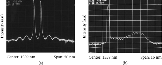
FIGURE 4.29
The comb-like optical spectra in two setups of the fiber ring laser using (a) model PM-315P and (b) model Mach-427, respectively.
4.7.3.2 Discrete Wavelength Tuning
One of the influences of the comb-like filtering effect is a discrete wavelength tuning in the FM mode-locked fiber ring laser. In our mode-locked fiber lasers, the mode locking happens only at the peaks of the comb-like optical spectrum where the lightwaves acquire sufficient energy gain to satisfy the mode-locking condition. The wavelength of the sequence of the mode-locked pulses can be tuned only by changing the modulation frequency of the phase modulator. Thus, the wavelength tuning is based on the matching of the dispersed spectrum of the pulse sequence, hence tuning of the pulse central passband [67,68]. The tuning range of the laser depends on the profile of gain spectrum and the total dispersion of the cavity. Because the gain spectrum is modulated by the interference between two polarization modes, the modulation frequency tuning is required by the amount of [67]
![]()
where fm is the modulation frequency, m is the harmonic order, and D and Lcav are the average dispersion and the total length of the ring cavity, respectively. We note that the tuning is only achieved in a specific range of wavelengths to prevent the competition of the CW modes, which suppress the mode locking at other matched wavelengths although the comb-like spectrum can be observed in most of the phase modulators.
In the setup using the phase modulator Mach-4027 with an integrated polarizer at its output, mode locking is achieved at a modulation frequency of about 1 GHz. A 100-m long Corning SMF-28 fiber is inserted after the PM to ensure that the average dispersion in the loop is anomalous. The total loop length is 190 m corresponding to a mode spacing of 1.075 MHz. By tuning the modulation frequency, the lightwaves in the cavity are mode locked to generate a short pulse sequence at the wavelength corresponding to one of the peaks of the comb spectrum as shown in Figure 4.29. A 0.46 nm average spacing between two adjacent mode-locked wavelengths is achieved. By adjusting the PC to optimize the gain spectrum, we can tune over 18 different wavelengths (1554 to 1562 nm) by simply changing the modulation frequency of 1.35 kHz as shown in Figure 4.30a. These measured parameters agree with the theoretically predicted values, which are of 0.4578 nm and 1.27 kHz, respectively. Figure 4.30b shows the pulsewidth and bandwidth-time (BT) product of a mode-locked pulse at 18 wavelengths. The average BT of 0.8 indicates that the output pulses are highly chirped, and they can be compressed by using a suitable dispersive fiber at the output of the laser. In wavelength tunable harmonically mode-locked fiber laser, the supermode noise is an important issue that requires some methods of suppression to improve performance of the generated pulse train [69]. It is worth noting that the mode-locked pulses at all 18 wavelengths are very clean, which is seen from the time trace and its corresponding RF spectrum shown in Figure 4.31. When the fm is tuned by an amount of δfm/2, the mode competition occurs strongly, which degrades the waveform of the output as shown in Figure 4.32. On the other hand, this is the transition state for switching to the adjacent spectral peak, and the mode locking cannot be totally achieved. When the wavelength is tuned to the edge of gain spectrum, multiwavelength operation of the laser can be easily excited, and it also affects the performance of mode-locked pulses as shown in Figure 4.33.

FIGURE 4.30
(a) The mode-locked wavelength versus modulation frequency and (b) measured characteristics of mode-locked pulse over the tuning range.

FIGURE 4.31
An example of (a) the time trace and (b) radio-frequency spectrum of the mode-locked pulse sequence at one of tuned wavelengths.
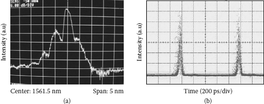
FIGURE 4.32
(a) Optical spectrum and (b) time trace of the output when modulation frequency fm is tuned by ±dfm/2.
Similarly, a wavelength tuning operation is also observed in the setup using the phase modulator PM-315P, although it is more difficult in adjustment of the polarization controller to obtain a sufficient gain bandwidth covering the tuning range of wavelength because of a wide spacing between. Only three wavelengths at the peaks of the comb-like spectrum are tuned with changing the modulation frequency of 3.1 kHz in this setup to obtain a high-quality pulse train with characteristics summarized in Table 4.2.
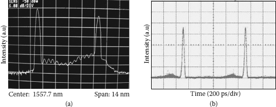
FIGURE 4.33
(a) Optical spectrum and (b) time trace of mode-locked pulse when the wavelength is tuned at the edge of gain spectrum.
TABLE 4.2
Pulse Characteristics at Tuned Wavelengths of the Frequency Modulation Mode-Locked Laser Using the Modulator PM-315P

4.7.4 Influence of Phase Modulator on Multibound Solitons
4.7.4.1 Formation of Multibound Solitons
The existence of comb-like filtering effects in the cavity using an EO phase modulator influences remarkably the characteristics of generated pulses. The artificial filter based on the birefringence of the cavity limits the gain bandwidth and contributes to the mechanism of pulse broadening due to the limitation of the pulse spectrum. This effect has been experimentally demonstrated by the results of pulse width obtained from two setups of the mode-locked fiber lasers using the modulators PM-315P and Mach-427. Although the modulator Mach-427 is driven at a much higher modulation index compared to the modulator PM-315P because of lower Vπ, the pulse generated from the setup using Mach-427 modulator is more than twice as wide as that generated from the setup using the PM-315P modulator. With a much smaller width due to broader gain bandwidth, the pulse generated in the case of PM-315P has a high peak power to create a sufficiently nonlinear phase shift that is necessary for pulse splitting in the cavity. Moreover, the effective interactions between pulses in bound states also depend on the pulse width through the overlap of long pulse tails and the chirping caused by phase modulation. In the case of PM-315P, the chirp imposed on the generated pulses with sufficient small width allows an effective attraction to balance the repulsion to generate a stable bound state. In contrast, a distinct bound state cannot be observed in the case of Mach-427 with wider-generated pulses as mentioned in Chapter 3. In this case wider pulses obtain higher chirp from the phase modulator, which results in a stronger attraction. At once the repulsion force from direct interaction becomes weaker. Therefore, a balanced interaction cannot be achieved in this case to generate a bound state with obviously resolved pulses although the cavity is strongly pumped. A state of mode-locked pulse with two-hump generated from the setup using Mach-427 has been observed as shown in Figure 4.34. This result may be a new solution of the fiber laser system, yet the time separation between two humps less than 20 ps may also indicate a strong attraction between two adjacent pulses.
Furthermore, the polarization sensitivity of the cavity also increases because of the inherent birefringence of the waveguide. Under a strong pumping scheme, some effects such as spectral hole burning (SHB) and polarization hole burning (PHB) are enhanced in the gain medium, and these make polarization-dependent loss and gain become more complex [70,71]. Inhomogeneous broadening of the gain spectrum associated with SHB and PHB effects [72,73] excites multiwavelength emission in the fiber ring laser, which results in a gain competition between different emission wavelengths. Typically only one of the emission wavelengths satisfies the phase-locking condition in the cavity to generate a pulse train, while other wavelengths may operate in the CW mode or FM mode depending on the polarization setting in the cavity. Thus, if the polarization setting is not optimized, the gain of the mode-locked wavelength can be reduced that results in a switching from higher-order bound solitons to lower-order bound solitons. Figure 4.35 shows a typical example of switching from the triple-bound soliton into the dual-bound soliton after the polarization controller is slightly adjusted. The gain reduction of the mode-locked wavelength always accompanies the gain enhancement of adjacent wavelengths as shown in Figure 4.35b. Therefore, it is understandable that the higher-order bound states are more sensitive to polarization settings. However, the polarization-dependent gain effect also provides a flexible mechanism for stabilization of the bound state by adjusting the input polarization state of the phase modulator. If the gain is too high, multibound solitons can fall into unstable states because of the phase fluctuation that leads to a breakdown of interactive balance between pulses. Therefore, a reduction of gain from tuning the polarization state can pull the ring laser back to the stable operation region.

FIGURE 4.34
A mode-locked state generating a two-hump pulse in the cavity using the phase modulator Mach-427. (a) Single pulse trace. (b) Pulse train trace.

FIGURE 4.35
A switching from the triple-bound soliton into the dual-bound soliton after an adjustment of the polarization controller. (a) Spectrum of triple-bound soliton. (b) Spectrum of dual-bound soliton with an adjacent wavelength in frequency modulation mode.
4.7.4.2 Limitation of Multibound Soliton States
According to the interaction mechanism of bound solitons in the active mode-locked fiber ring laser, an effective repulsion is induced by linear chirping caused by periodic phase modulation or a balanced interaction between solitons is only achieved around the extreme of modulation cycle where it approximates a parabolic function. However, this approximation is no longer valid if the width of the bunch is so wide. Deviation from linear chirping increases when the number of solitons in bound states increases. Thus, the pulses at the edge of the bunch would experience a nonlinear chirping, rather than linear chirping, which influences the balanced interaction of bound solitons. This explains why the trace of sextuple-bound solitons looks noisy because of oscillation of solitons in the bound state and the spectrum is slightly modulated due to a change in the relative phase difference. It has also been shown that the higher-order multibound solitons are more sensitive to environmental perturbations such as temperature variation. When the fluctuation of cavity length is under a slight detuning, the outer pulses in the multibound state would be most affected by the frequency shifting that breaks the balance in soliton interaction.
The chirping rate determines the separation between bound solitons as described in Chapter 3, and the chirp effect and the number of solitons in the bound states are also correlated. Figure 4.36a depicts the experimental threshold power for the creation of dual- and triple-soliton bound states against the phase modulation index that indicates the increase of required splitting optical power when the chirping is increased. An increase in the chirp rate requires a higher threshold power to maintain a specific number of pulses in the bound state. When the phase modulation index increases, the expansion of signal spectrum is enhanced. This is advantageous to not only shortening the pulse width but also more tightly binding the pulses due to the increase in number of phase-locked modes. However, the increase in chirping rate also causes an energy transfer to stronger sidebands that can degrade the soliton content of the pulse sequence. Although the up-chirped pulse is further compressed by anomalous dispersion of the fiber ring at a higher modulation index, the larger frequency chirp at pulse edges also may require higher energy contained in the pulses. This tendency agrees with the theoretical analysis of soliton production from the chirped pulses in [74,75]. At a low phase modulation index, the chirping is almost unaffected by the threshold power due to weak binding of the bound solitons. Consequently, the waveforms of the bound states are noisier and more sensitive to phase fluctuations caused by the ASE noise or the random polarization variation of the guided medium. A simulation result of the power limit of the cavity to maintain the bound state is shown in Figure 4.36b. The rates of increasing and decreasing peak power of bound solitons are indicated showing two distinct regions of operations, the triple and the double bound separated by the dashed bold line. This limit line (dashed bold line) is obtained when a minimum power level circulating in the cavity is required to maintain the bound state that divides the graph into the triple- and double-bound regions. At a specific modulation index, when the average power of the cavity decreases, the variation of the peak power is stronger. When the power is lower than the limit line, the higher-order soliton bound state switches to the lower-order soliton bound state. This tendency also indicates that the increase in chirping diminishes the number of solitons in the bound state at a specific optical power level as shown in Figures 4.37a and 4.37b. These figures show the evolution of the triple-soliton bound state in the cavity at the same average power level but different phase modulation indices that correspond to points A and B, respectively, in Figure 4.36b.
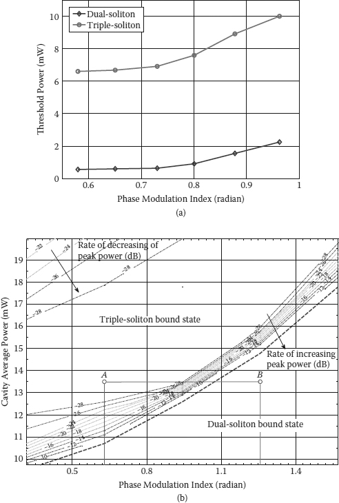
FIGURE 4.36
(a) Experimentally measured variation of threshold splitting power with the phase modulation index of the bound soliton states. (b) Simulated variation of the peak power of the triple-bound state with the phase modulation index.

FIGURE 4.37
(a,b) Simulated evolution of the triple-soliton bound state at operation points A and B, respectively, in Figure 4.36b.
Thus, the phase modulation profile affects significantly the multibound soliton states. In other words, multibound states can be modified by variation of the modulation curve of the phase modulator. Enhancement of higher-order harmonics in the modulation signal is the simplest way to modify the phase modulation profile. Similar to the rational harmonic mode locking, the higher-order harmonics of modulation frequency is strongly enhanced by saturation of the RF power amplifier. When the levels of the second- and the third-harmonics are sufficiently high to distort the phase modulation profile, multiple linear chirps in each modulation cycle can be created. In particular, there are two linear chirps in each modulation cycle created by increase in the input power of the RF amplifier higher than 2 dBm in our setup. In fact a submodulation cycle would appear beside the main cycle due to the enhancement of the second harmonics in the modulation signal. When the laser is locked in the harmonic mode locking scheme instead of rational harmonic mode locking at the same optical power level of various multibound solitons, the multibound solitons with a smaller number of solitons are formed at two linear chirp positions as shown in Figure 4.38. The distortion of the phase modulation profile splits higher-order bound solitons into two groups of lower-order bound solitons within the same cycle. Moreover, the change in the higher-order harmonics level also changes the distortion that varies the chirp rate between two groups of solitons. Figure 4.39 shows a variation of time separation between two solitons split from the dual-bound soliton state as a function of the RF input power. Thus, the time separation reduces according to the reduction of the higher harmonic level in the modulation signal. When the RF input power is decreased to 2 dBm, two groups of bound solitons emerge together to form higher-order multibound solitons with the number of solitons equal to the total of solitons in two groups. The emergence of two bound soliton groups is due to the almost disappearance of the submodulation cycle generated by the second harmonic RF signal. It is interesting to show that the change in temporal separation is a complete linear function of the second harmonic RF power as shown in Figure 4.40.

FIGURE 4.38
Splitting of multibound solitons: (a) dual-bound soliton, (b) triple-bound soliton, (c) quadruple-bound soliton, and (d) sextuple-bound soliton, into lower-order bound solitons.
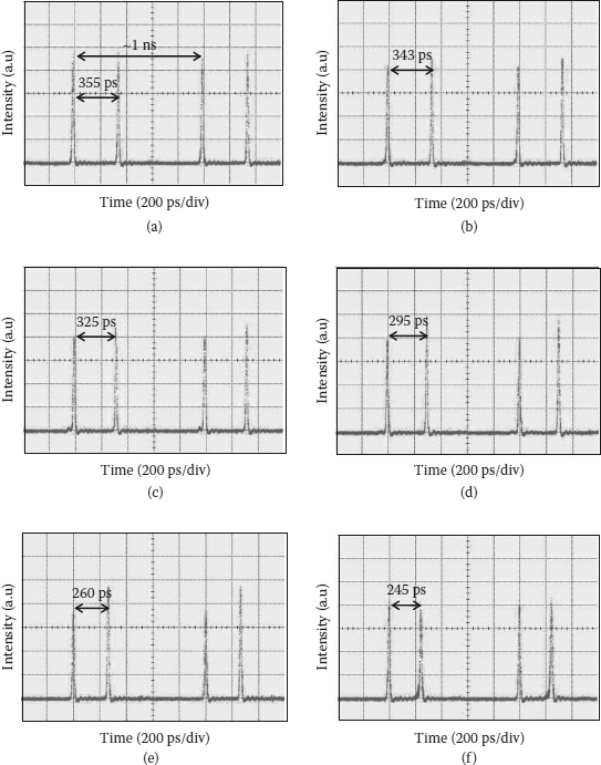
FIGURE 4.39
Time traces shows the variation of time separation between two solitons split from dual-bound soliton versus the change in RF input power: (a) 7 dBm, (b) 6 dBm, (c) 5 dBm, (d) 4 dBm, (e) 3 dBm, and (f) 2.5 dBm.

FIGURE 4.40
Correlation between the temporal spacing between two groups of bound soliton and the second harmonic radio-frequency power.
![]()
4.8 Remarks
In this section, we demonstrated the influence of the EO phase modulator on multibound solitons. The influence is reflected through two aspects of the phase modulator that consists of the inherent birefringence in the Ti:LiNbO3 waveguide and the phase modulation profile or chirp rate caused by the modulation signal. Two typical phase modulators have been described and characterized to indicate a difference in structure between the lumped type and the traveling-wave type that influences operation modes of the mode-locked fiber laser. Because an artificial comb-like response can be formed in the ring cavity by the birefringence of the integrated phase modulators, a narrow FSR in the response for the phase modulator with a long waveguide can limit the pulse shortening and multibound soliton formation. Moreover, the ability of discrete wavelength tuning can be implemented in the fiber laser through simple tuning of the modulation frequency.
Mode-locking and multibound soliton operation in the active FM-MLFRL is supported by linear chirping that can be approximated by a sinusoidal modulation. Besides the temporal separation of adjacent pulses, the optical power threshold for splitting the solitons and the number of solitons in the bound states are influenced by the chirp rate induced by this phase modulation. When the modulation profile is modified by the enhancement of the higher-order harmonic in the driving modulation signal, higher-order multibound solitons can be split into lower-order multibound solitons with controllable temporal separation between them. More importantly, the experimental results have demonstrated the ability of control through the active device such as an EO phase modulator that is important in potential applications.
![]()
References
1. B. A. Malomed, Bound Solitons in the Nonlinear Schrödinger-Ginzburg-Landau equation, Phys. Rev. A, 44, 6954, 1991.
2. B. A. Malomed, Bound Solitons in Coupled Nonlinear Schrödinger Equations, Phys. Rev. A, 45, R8321, 1992.
3. N. N. Akhmediev et al., Multisoliton Solutions of the Complex Ginzburg-Landau Equation, Phys. Rev. Lett., 79, 4047, 1997.
4. D. Y. Tang et al., Observation of Bound States of Solitons in a Passively Mode-Locked Fiber Laser, Phys. Rev. A, 64, 033814, 2001.
5. N. H. Seong and D. Y. Kim, Experimental Observation of Stable Bound Solitons in a Figure-Eight Fiber Laser, Opt. Lett., 27, 1321–1323, 2002.
6. P. Grelu et al., Phase-Locked Soliton Pairs in a Stretched-Pulse Fiber Laser, Opt. Lett., 27, 966–968, 2002.
7. D. Y. Tang et al., Bound-Soliton Fiber Laser, Phys. Rev. A, 66, 033806, 2002.
8. Y. D. Gong et al., Close Spaced Ultra-short Bound Solitons from DI-NOLM Figure 8 Fiber Laser, Opt. Commun., 220, 297–302, 2003.
9. P. Grelu et al., Relative Phase Locking of Pulses in a Passively Mode-Locked Fiber Laser, J. Opt. Soc. Am. B, 20, 863–870, 2003.
10. D. Y. Tang et al., Compound Pulse Solitons in a Fiber Ring Laser, Phys. Rev. A, 68, 013816, 2003.
11. B. Zhao et al., Energy Quantization of Twin-Pulse Solitons in a Passively Mode-Locked Fiber Ring Laser, Appl. Phys. B: Lasers and Opt., 77, 585–588, 2003.
12. Y. D. Gong et al., Regimes of Operation States in Passively Mode-Locked Fiber Soliton Ring Laser, Opt. and Laser Technol., 36, 299–307, 2004.
13. B. Ortac et al., Generation of Bound States of Three Ultrashort Pulses with a Passively Mode-Locked High-Power Yb-Doped Double-Clad Fiber Laser, Photonics Technol. Lett., IEEE, 16, 1274–1276, 2004.
14. B. Zhao et al., Passive Harmonic Mode Locking of Twin-Pulse Solitons in an Erbium-Doped Fiber Ring Laser, Opt. Commun., 229, 363–370, 2004.
15. D. Y. Tang et al., Multipulse Bound Solitons with Fixed Pulse Separations Formed by Direct Soliton Interaction, Appl. Phys. B: Lasers and Opt., 80, 239–242, 2005.
16. L. M. Zhao et al., Period-Doubling and Quadrupling of Bound Solitons in a Passively Mode-Locked Fiber Laser, Opt. Commun., 252, 167–172, 2005.
17. M. Grapinet and P. Grelu, Vibrating Soliton Pairs in a Mode-Locked Laser Cavity, Opt. Lett., 31, 2115–2117, 2006.
18. L. M. Zhao et al., Bound States of Dispersion-Managed Solitons in a Fiber Laser at Near Zero Dispersion, Appl. Opt., 46, 4768–4773, 2007.
19. W.-W. Hsiang et al., Stable New Bound Soliton Pairs in a 10 GHz Hybrid Frequency Modulation Mode-Locked Er-Fiber Laser, Opt. Lett., 31, 1627–1629, 2006.
20. L. N. Binh et al., Multi-bound Solitons in a FM Mode-Locked Fiber Laser, in Conference on Optical Fiber Communication/National Fiber Optic Engineers Conference, 2008. OFC/NFOEC 2008, 2008, pp. 1–3.
21. G. P. Agrawal, Optical Pulse Propagation in Doped Fiber Amplifiers, Phys. Rev. A, 44, 7493, 1991.
22. M. J. Lederer et al., Multipulse Operation of a Ti:Sapphire Laser Mode Locked by an Ion-Implanted Semiconductor Saturable-Absorber Mirror, J. Opt. Soc. Am. B, 16, 895–904, 1999.
23. F. X. Kurtner et al., Mode-Locking with Slow and Fast Saturable Absorbers—What’s the Difference?, IEEE J. Selected Topics in Quantum Electron., 4, 159–168, 1998.
24. D. Y. Tang et al., Stimulated Soliton Pulse Formation and Its Mechanism in a Passively Mode-Locked Fiber Soliton Laser, Opt. Commun., 165, 189–194, 1999.
25. D. Y. Tang et al., Mechanism of Multisoliton Formation and Soliton Energy Quantization in Passively Mode-Locked Fiber Lasers, Phys. Rev. A, 72, 043816, 2005.
26. A. B. Grudinin et al., Energy Quantisation in Figure Eight Fiber Laser, Electron. Lett., 28, 67–68, 1992.
27. G. Martel et al., On the Possibility of Observing Bound Soliton Pairs in a Wave-Breaking-Free Mode-Locked Fiber Laser, Opt. Lett., 32, 343–345, 2007.
28. A. Komarov et al., Ultrahigh-Repetition-Rate Bound-Soliton Harmonic Passive Mode-Locked Fiber Lasers, Opt. Lett., 33, 2254–2256, 2008.
29. J. N. Kutz et al., Stabilized Pulse Spacing in Soliton Lasers due to Gain Depletion and Recovery, IEEE J. Quantum Electron., 34, 1749–1757, 1998.
30. A. N. Pilipetskii et al., Acoustic Effect in Passively Mode-Locked Fiber Ring Lasers, Opt. Lett., 20, pp. 907-909, 1995.
31. W. H. Loh et al., Soliton Interaction in the Presence of a Weak Nonsoliton Component, Opt. Lett., 19, 698–700, 1994.
32. G. P. Agrawal, Nonlinear Fiber Optics, 3rd ed. Academic Press, San Diego, 2001.
33. L. Socci and M. Romagnoli, Long-Range Soliton Interactions in Periodically Amplified Fiber Links, J. Opt. Soc. Am. B, 16, 12–17, 1999.
34. F. Gutty et al., Stabilisation of Modelocking in Fiber Ring Laser through Pulse Bunching, Electron. Lett. 37, 745–746, 2001.
35. D. Y. Tang et al., Soliton Interaction in a Fiber Ring Laser, Phys. Rev. E, 72, 016616, 2005.
36. R. P. Davey et al., Interacting Solutions in Erbium Fiber Laser, Electron. Lett., 27, 1257–1259, 1991.
37. D. Krylov et al., Observation of the Breakup of a Prechirped N-Soliton in an Optical Fiber, Opt. Lett., 24, 1191–1193, 1999.
38. S. Longhi, Pulse Dynamics in Actively Mode-Locked Lasers with Frequency Shifting, Phys. Rev. E, 66, 056607, 2002.
39. C. R. Doerr et al. Additive-Pulse Limiting, Opt. Lett., 19, 31–33, 1994.
40. S. Wabnitz, Suppression of Soliton Interactions by Phase Modulation, Electron. Lett., 29, 1711–1713, 1993.
41. J. P. Gordon, Interaction forces among solitons in optical fibers, Opt. Lett., 8, 596–598, 1983.
42. Y. Kodama and K. Nozaki, Soliton interaction in optical fibers, Opt. Lett., 12, 1038–1040, 1987.
43. F. M. Mitschke and L. F. Mollenauer, Experimental Observation of Interaction Forces between Solitons in Optical Fibers, Opt. Lett., 12, 355–357, 1987.
44. S. Wabnitz, Suppression of Soliton Interactions by Phase Modulation, Electron. Lett., 29, 1711–1713, 1993.
45. T. Georges and F. Favre, Modulation, Filtering, and Initial Phase Control of Interacting Solitons, J. Opt. Soc. Am. B, 10, 1881889, 1993.
46. N. D Nguyen and L. N. Binh, Generation of Bound-Solitons in Actively Phase Modulation Mode-Locked Fiber Ring Resonators, Opt. Commun., 281, 2012–2022, 2008.
47. J. G. Proakis, Digital Communications. McGraw-Hill, New York, 2001.
48. L. J. Wang et al., Analysis of Polarization-Dependent Gain in Fiber Amplifiers, IEEE J. Quantum Electron., 34, 413–418, 1998.
49. H. A. Haus et al., Additive-Pulse Modelocking in Fiber Lasers, IEEE J. Quantum Electron., 30, 20208, 1994.
50. T. F. Carruthers et al., Active-Passive Modelocking in a Single Polarization Erbium Fiber Laser, Electron. Lett., 30, 1051–1053, 1994.
51. C. R. Doerr et al., Asynchronous Soliton Mode Locking, Opt. Lett., 19, 1958–1960, 1994.
52. J. J. O’Neil et al., Theory and Simulation of the Dynamics and Stability of Actively Modelocked Lasers, IEEE J. Quantum Electron., 38, 1412–1419, 2002.
53. L. N. Binh, Photonic Signal Processing: Techniques and Applications, CRC Press, Boca Raton, FL, 2008.
54. K. Kawano et al., A Wide-Band and Low-Driving-Power Phase Modulator Employing a Ti:LiNbO3 Optical Waveguide at 1.5 mu m, Photonics Technol. Lett., IEEE, 1, 33–34, 1989.
55. K. Kawano et al., New Travelling-Wave Electrode Mach-Zehnder Optical Modulator with 20 GHz Bandwidth and 4.7 V Driving Voltage at 1.52 mu m Wavelength, Electron. Lett., 25, 1382–1383, 1989.
56. K. Noguchi et al., A Broadband Ti:LiNbO3 Optical Modulator with a Ridge Structure, J. Lightwave Technol., 13, 1164–1168, 1995.
57. R. Tench et al., Performance Evaluation of Waveguide Phase Modulators for Coherent Systems at 1.3 and 1.5 µm, J. Lightwave Technol., 5, 492–501, 1987.
58. Y. Shi et al., High-Speed Electrooptic Modulator Characterization Using Optical Spectrum Analysis, J. Lightwave Technol., 21, 2358, 2003.
59. R. Regener and W. Sohler, Loss in Low-Finesse Ti:LiNbO3 Optical Waveguide Resonators, Appl. Phys. B: Lasers and Opt., 36, 143–147, 1985.
60. E. Chan and R. A. Minasian, A New Optical Phase Modulator Dynamic Response Measurement Technique, J. Lightwave Technol., 26, 2882–2888, 2008.
61. W. Leeb et al., Measurement of Velocity Mismatch in Traveling-Wave Electrooptic Modulators, IEEE J. Quantum Electron., 18, 14–16, 1982.
62. E. H. W. Chan and R. A. Minasian, Sagnac-Loop-Based Equivalent Negative Tap Photonic Notch Filter, Photonics Technol. Lett., IEEE, 17, 1741742, 2005.
63. R. Stubbe et al., Polarization Selective Phase Modulator in LiNbO3, Photonics Technol. Lett., IEEE, 2, 187–190, 1990.
64. G. Shabtay et al., Tunable Birefringent Filters—Optimal Iterative Design, Opt. Express, 10, 1534–1541, 2002.
65. C. O’Riordan et al., Actively Mode-Locked Multiwavelength Fiber Ring Laser Incorporating a Lyot Filter, Hybrid Gain Medium and Birefringence Compensated LiNbO3 Modulator, in Ninth International Conference on Transparent Optical Networks, 2007. ICTON ’07. 2007, pp. 248–251.
66. G. J. Sellers and S. Sriram, Manufacturing of Lithium Niobate Integrated Optic Devices, Opt. News, 14, 29–31, 1988.
67. S. P. Li and K. T. Chan, Electrical Wavelength Tunable and Multiwavelength Actively Mode-Locked Fiber Ring Laser, Appl. Phys. Lett., 72, 1954–1956, April 1998.
68. Y. Zhao et al., Wavelength Tuning of 1/2-Rational Harmonically Mode-Locked Pulses in a Cavity-Dispersive Fiber Laser, Appl. Phys. Lett., 73, 3483–3485, December 1998.
69. D. Lingze et al., Smoothly Wavelength-Tunable Picosecond Pulse Generation Using a Harmonically Mode-Locked Fiber Ring Laser, J. Lightwave Technol., 21, 93937, 2003.
70. T. Aizawa et al., Effect of Spectral-Hole Burning on Multi-channel EDFA Gain Profile, in Optical Fiber Communication Conference, 1999, and the International Conference on Integrated Optics and Optical Fiber Communication. OFC/IOOC ’99. Technical Digest, 1999, pp. 102–104, vol. 2.
71. M. Bolshtyansky, Spectral Hole Burning in Erbium-Doped Fiber Amplifiers, J. Lightwave Technol., 21, 1032, 2003.
72. D. Kovsh et al., Gain Reshaping Caused by Spectral Hole Burning in Long EDFA-Based Transmission Links, in Optical Fiber Communication Conference, 2006 and the 2006 National Fiber Optic Engineers Conference. OFC 2006, 2006, p. 3.
73. L. Rapp and J. Ferreira, Dynamics of Spectral Hole Burning in EDFAs: Dependency on Pump Wavelength and Pump Power, Photonics Technol. Lett., IEEE, 22, 1256–1258, 2010.
74. M. Desaix et al., Propagation Properties of Chirped Soliton Pulses in Optical Nonlinear Kerr Media, J. Phys. Rev. E, 65, 2002.
75. J. E. Prilepsky et al., Conversion of a Chirped Gaussian Pulse to a Soliton or a Bound Multisoliton State in Quasi-lossless and Lossy Optical Fiber Spans, J. Opt. Soc. Am. B, 24, 1254–1261, 2007.