
5
![]()
Transmission of Multibound Solitons
![]()
Le Nguyen Binh
Hua Wei Technologies, European Research Center, Munich, Germany
CONTENTS
5.2 Soliton Propagation in Optical Fibers
5.3 Transmission of Multibound Solitons
5.4 Dynamics of Multibound Solitons in Transmission
![]()
5.1 Introduction
Temporal solitons are attractive for long-haul fiber transmission systems due to their preservation of shape during propagation in nonlinear dispersive medium. In theory, the soliton character only remains unchanged in ideal transmission medium without any perturbation such as loss and noise. Therefore, the understanding of soliton propagation characteristics in real fiber systems is of significance to the design of an optical communication link. Moreover, there is a difference between propagation of solitons in a ring such as a mode-locked fiber laser and a real fiber transmission link. It must be noted that the length of the mode-locked fiber ring is much shorter than the dispersion length of the fiber, LD, and the pulse sequence is thus operating in the near field region in which the chirp of the lightwave occurs significantly, especially at the edges of the pulses, while the distance of each span in the fiber link is longer than the dispersion length. Therefore, distinct transmission conditions are required to ensure that solitons can be recovered at the end of the link.
Although a number of reports on bound soliton states in mode-locked fiber lasers have been published, to date there is no report on the propagation dynamics of multibound solitons in optical fiber. The difficulty of the generation of a stable bound soliton sequence in a passive mode-locked fiber laser may have prevented the investigation of their propagation and related dynamics. As described in the above chapters, the active frequency modulation (FM) mode-locked fiber laser offers a significant advantage in the generation of an ultrastable multibound soliton sequence at a modulation frequency that would be important for propagation in optical fiber. Dynamics of multibound solitons are an important issue for investigation. The obtained results are significant to possibly potential applications of bound soliton lasers.
![]()
5.2 Soliton Propagation in Optical Fibers
5.2.1 Loss Management
Because the group velocity dispersion (GVD) value is unchanged along in optical fibers, the balance between GVD and self-phase modulation (SPM) in soliton transmission would be achieved only if the soliton pulse was not attenuated during propagation. For a lossy fiber in the real transmission system, a reduction of the peak power over distance leads to a soliton broadening. The broadening of soliton can be understood by the reduction of the SPM effect resulting from the reduced peak power that makes the impact of the dispersion effect stronger during propagation. When the fiber loss is assumed as a weak perturbation of the nonlinear Schrödinger equation (NLSE), change in soliton parameters under the influence of the fiber loss has been investigated by using the variation method [1]. Variations of soliton amplitude and phase along the fiber can be given by
![]()
where and, α is the loss coefficient of the fiber. An exponential decrease in soliton amplitude weakens the SPM effect; hence, the soliton is also broadened with the same manner:
![]()
where T0 is the initial width of an unperturbed soliton, T is the width of a soliton at distance z. It notes that a linear increase in pulse width occurs in the linear propagation scheme [2]. When the peak power is considerably attenuated at a long distance, the SPM effect can be negligible and solitons behave like nonsolitary pulses. Therefore, the exponential dependence of soliton width over the distance is only valid at the distance where αz is less than 1.
In order to overcome the broadening problem due to the fiber loss effect, a periodic amplification of soliton is required to recover the soliton energy. A lumped amplification scheme can be used in a fiber link for this purpose [3]. Solitons that propagate in this scheme are called the path-average solitons [4]. Similar to the mode-locked fiber ring system, the adjustment of soliton in the fiber following the amplifier can lead to shedding of a part of soliton energy as dispersive waves that are accumulated to a considerable level over a large number of amplifiers. In order to keep variation of the soliton parameters negligible, two conditions to operate in the average-soliton regime must be satisfied [2,4]:
• The amplifier spacing LA must be much smaller than the dispersion length LD (LA << LD). This condition is required to keep radiation of dispersive waves negligibly small because the energy of dispersive waves is inversely proportional to the dispersion length LD.
• The input peak power of the soliton must be larger than that of the fundamental soliton by a factor
![]()
where Ps, P0 are the peak powers of the path-average soliton and the unperturbed soliton, respectively, G is the amplifier gain factor. This condition is to make certain that the average peak power over the LA is sufficient to balance the GVD effect.
The soliton energy varies periodically in each span due to the fiber loss, hence other parameters of soliton such as the width and the phase also change accordingly. However, the soliton remains unchanged at ultralong distance if the above conditions are satisfied.
But it is impractical to satisfy the first condition when the existing transmission fibers with LD of about 10 to 20 km are used for the long-haul transmission system [5,6]. If the LA is short, there are some disadvantages, such as the high cost and the large accumulated amplification stimulated emission (ASE) noise resulting from a large number of optical amplifiers. To facilitate the first condition, a distributed amplification scheme such as Raman amplification can be employed [7,8]. It is understandable that the variation of peak power is considerably reduced because the amplification process takes place along the transmission fiber. And this scheme allows a transmission with LA >> LD. However, an unstable soliton transmission can occur due to the resonance of the dispersive waves and solitons when that need to be carefully considered in the design of soliton transmission system [9].
5.2.2 Dispersion Management
The problem of soliton broadening in lossy fiber can also be overcome by using dispersion-decrease-fiber (DDF) in which its dispersion decreases exponentially corresponding to the reduction of the peak power. From the variation of soliton amplitude in (5.1), the variation of the GVD in DDF follows a function as
![]()
Thus, the reduction of the GVD is proportional to the reduction of the SPM effect; hence, solitons can remain unchanged during propagation in the DDF. However, the use of DDF in practical transmission systems is not feasible because of the availability of the DDF as well as the complexity of the system design. Furthermore, the performance would be degraded because the average dispersion along the link is large. Although this scheme is disadvantageous to the system, it is commonly applied for pulse compression based on the soliton effect [10,11].
Therefore, another option is use of dispersion management, which uses alternating positive and negative GVD fibers. This arrangement is commonly employed in high-speed transmission systems today because it offers a relatively improved performance [12,13]. Hence, using a periodic dispersion map along the fiber link has attracted extensive attention for its ability in soliton transmission. Both theoretical and experimental researchers have shown the advantages of dispersion-managed (DM) solitons [12]. Owing to alternating the sign of the fiber dispersion in one map period, the average GVD of the whole link can be kept in a small value while the GVD of each section is large enough to suppress the impairments such as four-wave mixing and third-order dispersion. Two important parameters of the map are the average GVD of the whole link and the map strength Sm , which are defined as follows [2]:
![]()
where β2n, β2a are the GVD parameters in the normal and anomalous sections of lengths ln and la, respectively, tFWHM is the full width at half of maximum (FWHM). It has been shown that the shape of DM solitons is closer to a Gaussian pulse rather than a “sech” shape, and their parameters such as the width, peak power, and chirp vary considerably in each map period. Therefore, depending on the map configuration, input parameters of DM solitons should be carefully chosen to ensure that the pulse can recover its state after each map period [14]. In addition, the peak power enhancement of DM soliton compared to the constant-GVD soliton allows an improvement of performance in terms of signal-to-noise ratio while suppressing timing jitter by reducing the average GVD. Interestingly, it has been confirmed that DM solitons exist not only in anomalous average dispersion but also in a normal average dispersion scheme [15]. However, the existence of DM soliton in the map with is obtained only when the strength of map Sm is greater than a critical value Scr , which is approximately 4 [16]. Hence, it is not surprising to observe the existence of solitons in the mode-locked fiber laser with normal average dispersion.
Interaction between solitons is an important issue in practice. Because properties of DM solitons are different from the average-GVD solitons, the evolution and dynamics of DM solitons have become more attractive for both theoretical and experimental studies [12,13]. Results of theoretical study have shown that a strong interaction prevents the DM solitons in a positive average GVD map from practical high-speed transmission applications, although they can exist [17]. This also indicates a complexity in the dynamics of DM solitons in propagation, beside a single soliton solution some complex solutions of DM soliton can exist in specific dispersion maps. In one study on a high-order DM soliton it showed a stable evolution of an antisymmetric (antiphase) soliton in the fiber at an ultralong distance [18]. Recently, the dispersion management was proposed to support a transmission of bisoliton, which consists of a couple of DM solitons with a zero-(in-phase) or π-(antiphase) phase difference [19]. By selecting appropriate parameters of the DM map and input pulse, a stable propagation of an in-phase bisoliton for a single channel and an antiphase bisoliton for the multichannel has been confirmed through numerical simulation [19]. In other studies, a structure called soliton molecules consisting of one dark and two bright solitons, which is similar to an asymmetrical soliton, has been numerically and experimentally demonstrated [20–23].
We can see that the soliton complexes in the above studies have a structure similar to pairs of bound solitons generated from the mode-locked fiber lasers. Stable propagation of the soliton complexes can offer new coding schemes for soliton transmission systems. In a conventional coding scheme, data bit “1” or “0” is represented by the presence or absence of a soliton pulse in each time slot. In one proposal, using the soliton complex such as bisoliton for new coding scheme provides code states with a residual bit for error prevention [19]. Therefore, it is necessary to have a new optical source that can generate the complex soliton like a bisoliton in new coding schemes. With the ability of multibound solitons generation, the active FM mode-locked fiber laser offers more states for a coding scheme that allows an improvement of performance and transmission of more than one data bit in each time slot. Hence, propagation characteristics of multibound solitons generated from the actively FM mode-locked fiber laser is of significance for potential applications of multibound soliton lasers in telecommunication systems.
![]()
5.3 Transmission of Multibound Solitons
5.3.1 Experimental Setup
To investigate the propagation dynamics of multibound solitons, various multibound solitons with ultrahigh stability from dual to quintuple states are generated by carefully optimizing the locking conditions of the fiber ring. These states are then propagating through standard single-mode optical fibers (SSMF) in order to investigate their propagation dynamics as shown in Figure 5.1. The length of the fiber is varied to prove the interaction between the soliton pulses. The estimated full width at half of maximum (FWHM) of the individual pulse of original bound soliton pairs (BSPs), triple-bound solitons (TBSs), and quadruple-bound solitons (QBSs) are 7.9, 6.9, and 6.0 ps, respectively. The time separation between two adjacent pulses is about three times of the FWHM pulse width. The repetition rate of these multibound soliton sequences is about 1 GHz.

FIGURE 5.1
Experimental setup for propagation of multibound solitons in a standard single fiber.
In this setup, a booster erbium-doped fiber amplifier (EDFA) is used before the transmission section to specify the power of multibound solitons launched into the SSMF. Through adjustment of the launched power, the multibound solitons can propagate under various transmission conditions from linear to nonlinear schemes. Two rolls of standard single-mode fiber with lengths of 1 km and 50 km are used for the investigation. After propagation, the outputs such as time trace and spectrum are monitored by the oscilloscope and the OSA, respectively.
5.3.2 Results and Discussion
It is obvious but worth mentioning that the binding property of the solitons circulating in the fiber ring is different under the case when they are propagating through the optical fiber. In the propagation these individual solitons would be interacting with each other, and naturally they are no longer supported by the periodic phase modulation as when circulating in the ring laser. When propagating through a dispersive fiber, the optical carrier under the envelope of generated multibound solitons is influenced by the chirping effects and then the overlapping between the soliton pulses. When the accumulated phase difference of adjacent pulses is π, the solitons repel each other [24–26]. The solitons in their multibound states acquire the down-chirping effect when propagating in SSMF due to its group velocity dispersion (GVD) induced phase shift. Hence, within the group of multibound solitons the front-end soliton would travel with a higher positive frequency shift, thus a higher group velocity than those at the back end of the multibound group which is influenced with lower negative frequency shift. Therefore, the time separation between adjacent pulses varies with the propagation distance. The variation of the time separation between pulses depends on their relative frequency difference. Figure 5.2 shows the waveforms and their corresponding spectra of triple-bound solitons at the transmitter. Figure 5.3(a) and (b) shows the dual bound solitons after transmission over 50 km of standard single mode fiber with 4.5 and 17 dBm launched power, respectively, after propagating over the fiber.
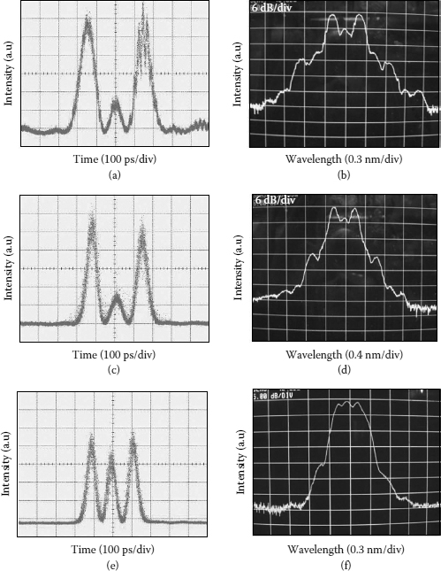
FIGURE 5.2
The time traces and corresponding spectra of the triple-bound soliton at launching powers of (a) through (d) 4.5 dBm, (b) through (e) 10.5 dBm, and © through (f) 14.5 dBm, respectively.

FIGURE 5.3
The time traces of the dual-bound soliton at launching powers of (a) 4.5 dBm, and (b) 17 dBm, respectively, after propagating through 50 km standard single-mode fiber.
Figure 5.3 shows the time traces of the dual-bound soliton launched in to the fiber span at launching powers of (a) 4.5 dBm, and (b) 17 dBm, respectively, after propagating through 50 km standard single-mode fiber. We can observe that at higher launched power, the solitons are bound stronger and thus much less broadening of the pulse is achieved. Similarly, a quadruple-bound soliton is launched in the same fiber span of 50 km at launching powers of 5 dBm, and 16.5 dBm. Its envelope is obtained at the span output and displayed in Figure 5.4. A launched power of about 15 dBm would allow a near preservation of the quadruple soliton. It is obvious that the higher the order of bound solitons, the higher the optical average power is required so that the binding of individual pulses can be preserved.

FIGURE 5.4
The time traces of the quadruple-bound soliton at launching powers of (a) 5 dBm, and (b) 16.5 dBm, respectively, after propagating through 50 km SSMF.
In all cases, the time separation significantly increases compared to the initial state due to the repulsion. In the ideal condition of propagation, direct interaction is the only factor that influences the time position and the pulse shape of solitons in bound states. However, propagation in a real optical fiber is considerably influenced by perturbations such as loss of fiber and initial launched powers (Pl) of solitons. The loss of fiber always leads to the broadening of bound solitons. Figures 5.5a and 5.5b show the dependence of pulse width and temporal separation of various multibound solitons with the launched power as a parameter. We observe similar dynamics in the propagation of dual, quadruple, and quintuple groups of solitons. In general, an increase in launched power leads to an enhanced shortening of the pulsewidth or a broadening of bound solitons at a lower rate, and thereby a reduction of the pulse temporal separation due to the enhancement of the nonlinear self-phase-modulation phase shift. Unlike the nearly linear variation of the pulsewidth, variation curves of the temporal separation show nonlinear launched power dependence. As observed in Figure 5.5b, two distinct areas of the curves can be observed as separated at the points A, B, and C. The intersection points A, B, and C of the two tangential curves correspond to the average soliton power (Psol) of the bound state. On the other hand, the points A, B, and C correspond to the minimum powers to launch the bound pulses for soliton propagation. For the transmission over standard single-mode fiber, it is observed that with the experimental parameters of the multibound solitons, the estimated average soliton powers for BSP, TBS, and QBS are 11, 13.5, and 15.2 dBm, respectively.


FIGURE 5.5
The launching power dependent variation of (a) pulsewidth, (b) time separation, and (c) peak power ratio of different multi-soliton bound states after 50 km propagation distance.
At Pl lower than Psol, and in addition to the fiber attenuation, the power of multibound soliton is not sufficient to balance the GVD effect. As a result, the pulse widths are rapidly broadened by self-alignment of the multibound solitons due to the perturbations accompanied by partly shading their energy in form of dispersive waves [2]. The broadening of such a dispersive wave is accumulated along the transmission fiber, and oscillations are formed around the multibound solitons as shown by the ripple of the tail of the soliton group in Figure 5.2a. Furthermore, the rate of broadening of the pulses is faster than that of the temporal separation at low launched powers leading to the enhancement of the overlapping between pulses. Therefore, the pulse envelope is consequently modulated by the interference of waves with the phase modulation effect due to the GVD that is the same as the fractional temporal Talbot effect [27,28]. Because of the parabolic symmetry of the anomalous GVD-induced phase shift profile around multibound solitons with a relative phase difference of π, the energy of the inner pulses is shifted to the outer pulses, and hence a decrease of the amplitude of inner pulses. (The frequency components of the inner pulses obtain higher relative velocity or propagate faster than those of the edge pulses that result in the energy transfer from the inner to the outer. This pattern also reconfirms the relative phase difference of π in the bound state.)
At Pl < Psol, the multibound states operate in a linear transmission scheme (picture the solitary waves). In contrast, at higher Pl, the SPM phase shift is increased to balance the GVD effect. The pulse width becomes narrower and the ripple of the pulse envelope is lower with higher level of launched power. For the dual-bound soliton, there is no difference in peak power of two pulses in the bound state. For the bound states with the number of solitons greater than two, however, there is significant difference between the inner and the outer pulses because of the energy transfer at Pl < Psol. Owing to the soliton content in pulses is enhanced at the average soliton power, there is a jump of peak power ratio between inner and outer pulses as shown in Figure 5.5c.
![]()
5.4 Dynamics of Multibound Solitons in Transmission
To verify the experimental results as well as to identify the evolution of multibound solitons propagation in the fiber, we model the multibound solitons as [29]
![]()
with N as the number of solitons in a bound state, and
![]()
where Ai and q0 are amplitude and time separation of solitons, respectively, and the phase difference Δθ = θi+1 – θi = π. The propagation of multibound solitons in SSMF is governed by the nonlinear Schrödinger equation with the input parameters as those obtained in the experiment. Shown together with experimental results in Figures 5.5a through 5.5c are the simulation evolution of the parameters (solid curves) over 50 km propagation of various orders of multisoliton bound states. The simulated evolution of the triple-bound soliton is shown in Figure 5.6 over 50 km SSMF, while Figure 5.7 shows the pulse shape and corresponding spectrum of the outputs at various launched power levels. The simulated results generally agree well with those obtained in the experiment (see Figure 5.2). The small residual chirp caused small difference between the experimental and numerical results. Dynamics of multibound solitons consisting of dual bond soliton (DBS), triple bond soliton (TBS), and quadruple bond soliton (QBS) during propagation are shown from Figure 5.8 to Figure 5.10. In each figure, respectively, the evolution of multibound solitons parameters such as the pulse width, the temporal separation between solitons, the ratio between the pulse width and the pulse separation and the peak power of the solitons, is simulated along the transmission fiber with different launched powers. The difference between lower and higher launching powers also obviously exhibited in simulated results. When the launched powers is far from the soliton power Psol, there is oscillation or rapid variation of parameters at initial propagation distance due to the adjustment of multibound solitons to perturbations of propagation conditions as mentioned above. The pulses are compressed at Pls higher than Psol, while they are rapidly broadened at Pls lower than Psol. The slow variation of parameters occurs at Pl close to Psol. However, the time separation of solitons remains unchanged in the propagation distance of one soliton period. We have validated this prediction in our experiment.

FIGURE 5.6
Numerically simulated evolutions of the triple-bound soliton over 50 km SSMF propagation at Pl of respectively (a) 5 dBm, (b) 10 dBm, and (c) 14 dBm.

FIGURE 5.7
Row (a) Numerically simulated output pulse shape and Row (c) optical spectrum of triple-soliton bound state over 50 km SSMF propagation at Pl of respectively 5 dBm, 10 dBm, and 14 dBm, (c), (d),.and (f) are corresponding spectra of bound-solitons depicted in (a), (b), and (c), respectively.

FIGURE 5.8
Evolution of numerically simulated dual-soliton bound state after 50 km propagation distance of SMF-28 fiber: (a) pulse width, (b) temporal separation, (c) ratio between pulse width and separation, and (d) peak power.
Another important property of multibound solitons is the phase difference between pulses that can be determined by the shape of the spectrum. We monitored the optical spectrum of the multibound solitons at both the launched end and the output of the fiber length. The modulated spectrum of multibound solitons is symmetrical with carrier suppression due to a relative phase relationship of π between adjacent solitons. After 50 km propagation at low Pl, both experimental and simulated results show that the spectrum of multibound solitons is nearly the same as that at the launched end (see Figure 5.2d and Figure 5.7d). In a linear-like scheme where the SPM effect is negligible, the GVD only modulates the spectral phase which modifies the temporal profile, but does not modify the spectrum of the bound state. The modulation of the spectrum is modified with an increase in Pl. At sufficient high Pl, the nonlinear phase shift-induced chirp is increased at the edges of pulses. Although the nonlinear phase shift reduces the GVD effect, the phase transition between adjacent pulses is changed due to the direct impact of the nonlinear phase shift. Hence, the small humps in the spectra of multibound states are strengthened, and they may be comparable to main lobes due to enhancement of the far interaction between pulses as shown in Figure 5.2f and Figure 5.7f. Figure 5.11 shows the variation of the relative phase difference between adjacent pulses in various multibound soliton states over 50 km propagation. The simulated results also indicate that the relative phase difference varies differently between two adjacent pulses in propagation. Although the phase difference of π between two central pulses in even-soliton bound states such as DBS and QBS can remain unchanged, it varies in general along propagation distance. At low Pl in all cases, the phase difference is varied to zero or π/2 value, then recovered to π at the output of the 50 km fiber. When the SPM phase shift becomes significant, the phase difference varies in the same manner in the first 40 km propagation, and then it tends to π/2 that modifies the corresponding spectrum.
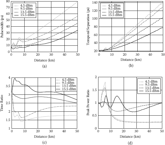
FIGURE 5.9
Evolution of numerically simulated triple-soliton bound state after 50 km propagation distance of SMF-28 fiber: (a) pulse width (b) temporal separation (c) ratio between pulse width and separation (d) peak power ratio between inner pulse and outer pulse.

FIGURE 5.10
Evolution of numerically simulated quadruple-soliton bound state after 50 km propagation distance of SMF-28 fiber: (a) pulse width (b) temporal separation (c) ratio between pulse width and separation (d) Peak power ratio between inner pulse and outer pulse.

FIGURE 5.11
Evolution of the phase difference between adjacent pulses over 50 km propagation in various bound states: (a) dual-bound soliton, (b) triple-bound soliton, and (c) quadruple-bound soliton.
![]()
5.6 Concluding Remarks
Characteristics of multibound soliton in propagation over 50 km SSMF fiber have been investigated in this chapter. Depending on the launched power level, the variation of multibound states parameters can divide into two propagation schemes: linear and soliton schemes. At low launched power in the linear propagation scheme, the modulated spectrum of multibound states remains unchanged due to the preservation of the phase difference of π, yet the temporal shape is modified so that it can be used to reconfirm the phase difference. At high launched power in a soliton propagation scheme, the modulated spectrum of multibound states is modified due to the enhancement of the SPM effect; however, the pulses in the bound state behave similar by to the single soliton transmission in perturbed conditions.
![]()
References
1. K. J. Blow and N. J. Doran, The Asymptotic Dispersion of Soliton Pulses in Lossy Fibers, Opt. Commun., 52, 367–370, 1985.
2. G. P. Agrawal, Nonlinear Fiber Optics, 3rd ed. Academic Press, San Diego, 2001.
3. M. Nakazawa et al., Soliton Amplification and Transmission with Er3+-Doped Fiber Repeater Pumped by GaInAsP Diode, Electron. Lett., 25, 199–200, 1989.
4. A. Hasegawa and Y. Kodama, Guiding-Center Soliton, Phys. Rev. Lett., 66, 161, 1991.
5. Y. Kodama and A. Hasegawa, Amplification and Reshaping of Optical Solitons in Glass Fiber II, Opt. Lett., 7, 339–341, 1982.
6. Y. Kodama and A. Hasegawa, Amplification and Reshaping of Optical Solitons in Glass Fiber? III. Amplifiers with Random Gain, Opt. Lett., 8, 342–344, 1983.
7. A. Hasegawa, Amplification and Reshaping of Optical Solitons in a Glass Fiber-IV: Use of the Stimulated Raman Process, Opt. Lett., 8, 650–652, 1983.
8. L. F. Mollenauer and K. Smith, Demonstration of Soliton Transmission over More than 4000 kmin Fiber with Loss Periodically Compensated by Raman Gain, Opt. Lett., 13, 675–677, 1988.
9. L. Mollenauer et al., Soliton Propagation in Long Fibers with Periodically Compensated Loss, IEEE J. Quantum Electron., 22, 157–173, 1986.
10. M. Nakazawa, Tb/s OTDM technology, in 27th European Conference on Optical Communication, Optical Communication, 2001. ECOC ’01. 2001, 184–187, vol. 2.
11. L. Ju Han et al., Wavelength Tunable 10-GHz 3-ps Pulse Source Using a Dispersion Decreasing Fiber-Based Nonlinear Optical Loop Mirror, IEEE J. Selected Topics in Quantum Electron., 10, 181–185, 2004.
12. A. Sano and Y. Miyamoto, Performance Evaluation of Prechirped RZ and CS-RZ Formats in High-Speed Transmission Systems with Dispersion Management, J. Lightwave Technol., 19, 1864–1871, 2001.
13. J. Fatome et al., Practical Design Rules for Single-Channel Ultra High-Speed Dense Dispersion Management Telecommunication Systems, Opt. Commun. 282, 1427–1434, 2009.
14. E. Poutrina and G. P. Agrawal, Design Rules for Dispersion-Managed Soliton Systems, Opt. Commun., 206, 193–200, 2002.
15. J. H. B. Nijhof et al., Stable Soliton-Like Propagation in Dispersion Managed Systems with Net Anomalous, zero and Normal Dispersion, Electron. Lett., 33, 1726–1727, 1997.
16. J. H. B. Nijhof et al., Energy Enhancement of Dispersion-Managed Solitons and WDM, Electron. Lett., 34, 481–482, 1998.
17. T. Inoue et al., Interactions between Dispersion-Managed Solitons in Optical-Time-Division-Multiplexed Systems, Electron. Commun. in Jpn. (Part II: Electron.), 84, 24–29, 2001.
18. C. Paré and P. A. Bélanger, Antisymmetric Soliton in a Dispersion-Managed System, Opt. Commun., 168, 103–109, 1999.
19. A. Maruta et al., Bisoliton Propagating in Dispersion-Managed System and Its Application to High-Speed and Long-Haul Optical Transmission, J. IEEE Selected Topics in Quantum Electron., 8, 640–650, 2002.
20. M. Stratmann et al., Dark Solitons Are Stable in Dispersion Maps of Either Sign of Path-Average Dispersion, in Summaries of Papers Presented at the Quantum Electronics and Laser Science Conference, 2002. QELS ’02. Technical Digest, 2002, p. 226.
21. M. Stratmann and F. Mitschke, Bound States between Dark and Bright Solitons in Dispersion Maps, in Summaries of Papers Presented at the Quantum Electronics and Laser Science Conference, 2002. QELS ’02. Technical Digest. 2002, pp. 226–227.
22. M. Stratmann et al., Experimental Observation of Temporal Soliton Molecules, Phys. Rev. Lett., 95, 143902, 2005.
23. I. Gabitov et al., Twin Families of Bisolitons in Dispersion-Managed Systems, Opt. Lett., 32, 605–607, 2007.
24. J. P. Gordon, Interaction Forces among Solitons in Optical Fibers, Opt. Lett., 8, 596–598, 1983.
25. Y. Kodama and K. Nozaki, Soliton Interaction in Optical Fibers, Opt. Lett., 12, 1038–1040, 1987.
26. F. M. Mitschke and L. F. Mollenauer, Experimental Observation of Interaction Forces between Solitons in Optical Fibers, Opt. Lett., 12, 355–357, 1987.
27. J. Azana and M. A. Muriel, Temporal Self-Imaging Effects: Theory and Application for Multiplying Pulse Repetition Rates, IEEE J. Selected Topics in Quantum Electron., 7, 728–744, 2001.
28. N. D. Nguyen et al., Temporal Imaging and Optical Repetition Multiplication via Quadratic Phase Modulation, in Information, Communications and Signal Processing, 2007 Sixth International Conference on, 2007, pp. 1–5.
29. N. D. Nguyen and L. N. Binh, Generation of Bound-Solitons in Actively Phase Modulation Mode-Locked Fiber Ring Resonators, Opt. Commun., 281, 2012–2022, 2008.