Chapter 9. Drawing with Pixels
Bitmap Caching
The BitmapData Class
Blend Modes
Bitmap Filters
Color Effects
Image Encoding and Saving
Adding Functionality to Your Color Picker
What’s Next?
Though largely known for its focus on vector assets, ActionScript also has an impressive arsenal of bitmap compositing features—options that work by layering, blending, and filtering pixel-based assets. ActionScript can even take a snapshot of vectors and manipulate the snapshot—behind the scenes with no loss in vector quality—giving you additional compositing options and, in many cases, performance gains.
Although it’s unrealistic to expect ActionScript to achieve the feature breadth and depth of a pixel-editing application like Adobe Photoshop, you really can accomplish quite a bit with it. Among others, ActionScript features include a set of blend modes (darken, lighten, multiply, screen, and others that closely resemble Photoshop blend modes), basic filters (like drop shadow, bevel, and blur, akin to Photoshop layer styles), and advanced filter effects (like convolution and displacement mapping, similar to Photoshop filters).
Today, ActionScript 3.0’s speed and efficiency make bitmap manipulation practical in more processor-intensive scenarios than ever before. In this chapter, we’ll discuss several ways to add pixel pushing to your projects, including:
Bitmap Caching. Moving pixels on screen is a lot more efficient than recalculating the math required to display moving vectors every time a frame renders. Temporarily caching a bitmap representation of a vector asset can reduce this strain and increase performance.
The
BitmapDataClass. Just as you use theGraphicsclass to draw with vectors, you can use theBitmapDataclass to draw with pixels.Blend Modes. ActionScript can blend assets together to alter the appearance of one or more assets. Included are a standard set of blend modes, which you might find in a typical bitmap editing application, such as Darken, Multiply, Lighten, Screen, and so on. We’ll also discuss a few ActionScript-specific blend modes that use transparency to great effect.
Bitmap Filters. Advanced filtering techniques such as blurring, sharpening, embossing, and distorting images can also be applied at runtime. They can even be applied to vector symbol instances, as well as bitmaps, without losing any fidelity or access to vector properties.
Color Effects. ActionScript 3.0 offers a few ways to manipulate color, ranging from applying simple tints to full manipulation of red, green, blue, and alpha channels of bitmap data.
Image Encoding. Bitmap data can even be encoded and saved in an external graphics format like JPG or PNG, using additional ActionScript libraries.
Bitmap Caching
First, we need to clear up a misconception: manipulating bitmaps in ActionScript does not mean you’ll lose all the advantages of crisp, clean vectors. ActionScript offers multiple ways to work with bitmap information, and, as you’ll see, vectors and bitmaps can work together well. In fact, using bitmaps judiciously can help you improve the look and performance of your vector animations.
Vector animations can sometimes lag behind comparable bitmap animations because they’re much more processor intensive to manipulate. The resources needed to render all the vectors every time an update is required is invariably more demanding than moving and compositing bitmaps.
With that in mind, ActionScript has the capability of caching, or temporarily storing, a version of a vector asset as a bitmap. It can then work with the bitmap instead of the original vector until it’s no longer optimal to do so. For example, consider a complex vector background over which other vectors are changing. If the background is unchanging, there’s no need to redraw the vector background repeatedly. Instead, it’s more efficient to work with the changing foreground elements on top of a bitmap. This situation is ideal for bitmap caching, the syntax for which is shown here:
displayObject.cacheAsBitmap=true;
By setting the cacheAsBitmap property to true, you can tell Flash Player to create a surface, a cosmetically identical bitmap representation of a symbol, to use for display purposes. Viewers won’t notice the difference, because the bitmap snapshot of the symbol is always kept current, through any changes, to prevent degradation of image quality. For example, if the symbol is scaled, the original cached bitmap is discarded and a new version is generated.
Because of this automatic updating feature, knowing when, and when not, to use bitmap caching is important. For example, if you’re moving several complicated vector assets around the stage, but doing little to alter their appearance, bitmap caching can dramatically improve performance. However, it’s usually unwise to enable caching if you’ll be scaling, rotating, or changing the opacity of a display object frequently. These operations change the appearance of the display object, and it must be composited again with any surrounding elements. Therefore, a new cache is created each time such a change is made, so making many changes (and therefore caching frequently) in quick succession can slow things down.
Soft-Edged Masks
Optimizing performance isn’t the only reason to use cacheAsBitmap. Some features require this property to be true in order to function. For example, although you can use ActionScript to assign one display object to mask another, the mask has sharp edges by default because it can’t use varying degrees of alpha transparency. That is, any nontransparent pixel, no matter what its alpha value, is considered opaque when added to the mask.
Note
A mask is used to reveal a portion of a display object. Only the areas of the display object that overlap with the mask area are visible.
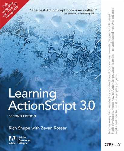
If you use bitmap caching for both the masker (the display object that will serve as the mask) and maskee (the display object that will be masked), however, ActionScript can composite the two elements as bitmaps. This allows alpha masks to composite semitransparent pixels using their actual alpha values to create a soft edge. Figure 9-1 illustrates this effect. The top image is of the mask itself, showing a soft edge. The middle image is the default appearance of an ActionScript mask, even when the mask contains varying degrees of opacity. The bottom image shows the same mask in use, but this time both the mask and revealed display object have their cacheAsBitmap property set to true.
The following code snippet can be found in the as_mask.fla source file, which has two movie clips on the stage, with instance names of maskee and masker.
1 masker.cacheAsBitmap=true; 2 maskee.cacheAsBitmap=true; 3 maskee.mask= masker;
The BitmapData Class
The BitmapData class is the real workhorse when it comes to ActionScript pixel-based manipulations. As its name implies, an instance of the BitmapData class contains not a bitmap, but the pixel color and alpha data that often comprise a bitmap. As with bitmap caching, you need not be confined to working with actual bitmaps to create a bitmap data instance. You can draw bitmap data from scratch or derive it from vector assets just as easily as from bitmap assets. Think of the latter process as working with a screenshot. Whether the display object contains a bitmap or a vector shape is immaterial. You can capture the bitmap data of that object in either case. Let’s start by looking at creating bitmap data from scratch and highlighting the difference between bitmap data and a bitmap.
Creating Opaque Bitmaps
There are two parts to creating a bitmap. One is the bitmap display object, and the other is the bitmap data. The bitmap display object is the picture you see on stage, and the bitmap data is a detailed description of the number of pixels used, their individual colors and alpha values, and so on. Your ultimate goal may be to display a bitmap, but you may also find it advantageous to work with bitmap data without ever actually displaying the pixels in question! (You’ll do just that later in the chapter when we demonstrate using a displacement map.)
In our next example, we want to see the fruit of our labors, so we’ll work with both bitmap data and a bitmap. The following script, found in the bitmap_from_scratch.fla source file, creates an instance of the BitmapData class, creates a bitmap using that data, and adds the bitmap to the display list. Without setting the x or y property of the bitmap, it appears at (0, 0).
1varbmd:BitmapData=new BitmapData(100, 100,false, 0xFF0000FF); 2varbm:Bitmap=new Bitmap(bmd); 3addChild(bm);
The first two arguments sent to the BitmapData class are the dimensions of the instance (100 × 100 pixels, in this example), and are required. If you intend only to create an empty BitmapData instance into which you’ll add content later, you need not add the remaining arguments. If you want to add visible pixels to your data instance at this stage, however, you can dictate the transparency and color of the data.
Note
The maximum size of a BitmapData object in Flash Player 10 is determined by a combination of total number of pixels and dimensions. It can’t exceed 16,777,215 pixels. When creating a bitmap, square dimensions can’t exceed 4095 × 4095 pixels, and a single side can’t exceed 8,191 pixels. Currently, it’s possible to load bitmaps that exceed these side restrictions, as long as the total pixel count doesn’t exceed 16,777,215 pixels. This may change in the future. For more information, see http://kb2.adobe.com/cps/496/cpsid_49662.html.
Flash Player 9 limits are considerably more restrictive. BitmapData instances can’t exceed 8,294,400 pixels (2880 × 2880) or 2880 pixels on any side.
If you exceed the maximum value in either dimension, in either player version, an instance is not created.
The third parameter tells the class that this instance will not be transparent. The last parameter is the color desired, but it uses a format we haven’t discussed previously. Instead of using the familiar 0xRRGGBB format, this class parameter must communicate alpha values, and thus requires the 32-bit 0xAARRGGBB hexadecimal format. This format adds two digits for alpha data at the beginning of the number. Line 1 of this code specifies FF, or full opacity, and then 0000FF, or blue, for the color. The result of this script is a 100 × 100–pixel, 100-percent opaque, blue square positioned at (0, 0).
Creating Bitmaps with Transparency
To create a bitmap data object with transparency, you must change the third parameter of the class constructor to true and then reduce the opacity of the color value. The first pair of characters in the hexadecimal number (from left to right) represents alpha (AA in the 32-bit format listed previously). The acceptable alpha range is 00 (fully transparent) to FF (fully opaque). For example, the following code, found in the bitmap_from_scratch_transparency.fla source file, creates a green square that is 50-percent transparent. The alpha value is 80, or half of the alpha range. The color that follows is then 00FF00, or green, corresponding with the RRGGBB format.
Note
The hexadecimal value 0x80 is equivalent to 128, or half of the 0–255 range for red, blue, green, and alpha channels of a color.
1varbmd:BitmapData=new BitmapData(100, 100,true, 0x8000FF00); 2varbm:Bitmap=new Bitmap(bmd); 3addChild(bm);
Using a Bitmap from the Library
If you need to work with an actual bitmap image, rather than originating your own BitmapData object, you can add an imported bitmap dynamically from the library. You can use the bitmap_from_library.fla file from the accompanying source code for this exercise, or use your own image. You must have an image already imported into the library and have given it a class name in the Linkage Properties dialog.
Note
When adding a linkage class name to a symbol, you needn’t actually create a class file first. The compiler will create an internal placeholder for you, which will automatically be replaced by an actual class should you later decide to create one. For more information, see the Adding Custom Symbol Instances to the Display List section of Chapter 4.
In our sample source file, a 550 × 400–pixel image of penguins has been given the linkage class name Penguins. Discussed briefly in Chapter 8, the base class for a library bitmap is BitmapData. This allows you to easily access the data without requiring that you first create an instance of the Bitmap. If you want to display a bitmap, objects for both BitmapData and Bitmap must be created.
Note
Loading a bitmap from an external source is discussed in Chapter 13.
The following three lines, found in the bitmap_from_library.fla source file, create both objects, and add the bitmap to the display list.
1varpenguinsBmd:BitmapData=newPenguins(550, 400); 2varpenguinsBm:Bitmap=new Bitmap(penguinsBmd); 3addChild(penguinsBm);
Note
Typing your bitmap data instance as BitmapData, rather than the linkage class name (Penguins, in this case) is more flexible because any bitmap data can be put into the variable. However, if you want your data type checking to be stricter, you can type to the linkage class name, instead:
varpenguinsBmd:Penguins =newPenguins(550, 400);
This will restrict the variable to accepting only the Penguins data.
In the section Creating Opaque Bitmaps earlier in this chapter, we said that the first two parameters of the BitmapData constructor, width and height, are required. This makes sense when you’re creating bitmap data from scratch, but is a bit inconsistent when instantiating a bitmap from the library. Thinking about your past experience with creating movie clips and text fields, for example, it may be more intuitive to try this:
varpenguinsBmd:BitmapData=newPenguins();
However, in earlier versions of most ActionScript editors, including Flash Professional CS3 and CS4, this will cause the compiler to generate the error: Incorrect number of arguments. Expected 2. This behavior has been improved in Flash Professional CS5, which will no longer issue this error, allowing you to create a BitmapData instance from a library bitmap in a manner consistent with the instantiation of many other objects.
Fortunately for users of older ActionScript compilers, the exact width and height values are not required when using a preexisting bitmap (as in the preceding penguins example). The BitmapData class will update these values and the data will be placed into the instance variable without scaling. If you’re uncertain about the dimensions of the bitmap you want to instantiate, just use (0, 0).
Note
For improved compatibility with multiple ActionScript compilers, we’ll continue to use 0 for width and height when creating a BitmapData instance from a bitmap symbol of unknown size. Those of you using current compilers can try omitting these values, if you prefer.
Copying Pixels
In the previous example, you populated an instance of the BitmapData class with a bitmap. But what if you want to work with only a portion of a bitmap? You can simply copy pixels from one BitmapData instance to another. The exercise that follows uses the copyPixels() method to create a new penguin bitmap by copying a segment from another bitmap. The method is called from a new BitmapData instance (into which you’re copying) and requires three parameters: the source object, a rectangle defining the pixels to be copied, and the destination point in the new object to which the pixels should be copied.
The following code is found in the copy_pixels_stage_click.fla source file. Lines 1 through 3 create the original penguin bitmap, as seen in the prior example. Line 4 adds a listener to the stage to call the onClick() function when the mouse is clicked. This is where the pixel copying takes place, which we’ll explain after the code.
1varpenguinsBmd:BitmapData=newPenguins(550, 400); 2varpenguinsBm:Bitmap=new Bitmap(penguinsBmd); 3addChild(penguinsBm); 4stage.addEventListener(MouseEvent.CLICK, onClick,false, 0,true); 5 6functiononClick(evt:MouseEvent):void{ 7varrect:Rectangle=new Rectangle(290, 196, 95, 170); 8varpenguinCopyBmd:BitmapData=new BitmapData(95, 170); 9 penguinCopyBmd.copyPixels(penguinsBmd, rect,new Point()); 10 11varpenguinCopyBm:Bitmap=new Bitmap(penguinCopyBmd); 12 penguinCopyBm.x= 385; 13 penguinCopyBm.y= 196; 14addChild(penguinCopyBm); 15 }
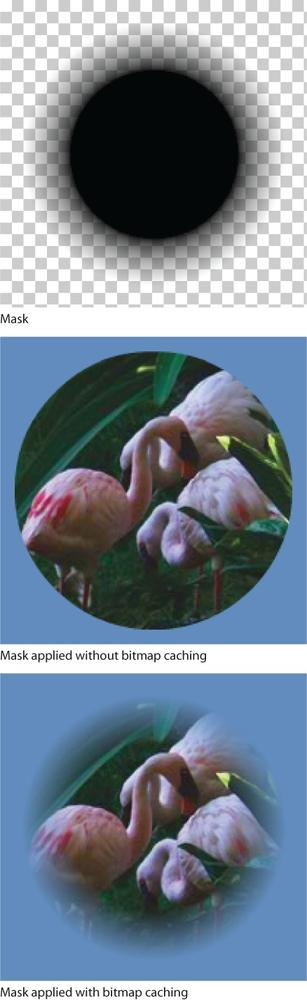
Line 7 defines the rectangle required to specify the area you want to copy. The Rectangle class requires the rectangle’s x and y location, and width and height. Figure 9-2 shows these values in a detail of the source material. We want to reference the area outlined in red, which is 95 × 170, but begins at (290, 196) from the upper-left corner of the bitmap.
Line 8 creates a new BitmapData instance the size of the desired rectangle. Line 9 concludes the copy process by copying the pixels into the new BitmapData instance, using the original source (penguinsBmd), the area to be copied (rect), and the destination for the copied pixels. We want to copy the pixels into a new bitmap, so for the last parameter, we just use a default Point instance to copy into (0, 0) of the new bitmap.
Note
For more information about the Rectangle or Point classes, see Chapter 7.
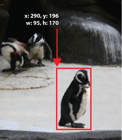
Finally, lines 11 through 14 create a new bitmap from the copied pixels, position it next to the original penguin, and add the new bitmap to the display list so it appears atop the original. The result is seen in detail view in Figure 9-3.
By design, this exercise demonstrates that not all display objects are interactive. The preceding code attached the mouse listener to the stage because we can’t attach a listener to a bitmap.
If you want a bitmap to serve as a button, however, you can place the bitmap into an interactive display object, such as a sprite. In the code excerpt that follows, found in the copy_pixels_sprite_click.fla source file, note that the step to add the bitmap to the stage, and the stage listener (lines 3 and 4 from the preceding script), have both been removed. In their place (indicated by the bold code), the bitmap is placed inside a new sprite and a listener is attached to that sprite, rather than the stage.
16varpenguinsBmd:BitmapData=newPenguins(550, 400); 17varpenguinsBm:Bitmap=new Bitmap(penguinsBmd); 18varsp:Sprite=new Sprite(); 19 sp.addChild(penguinsBm); 20addChild(sp); 21 sp.addEventListener(MouseEvent.CLICK, onClick,false, 0,true);
Drawing into a Bitmap
Sometimes it’s simpler to draw the entire contents of a bitmap data source into another, rather than copying pixels. For example, this is often true when you want to draw into a bitmap repeatedly or build bitmaps from multiple sources. Let’s demonstrate this by actually painting on a canvas. In the paint_tool.fla source file, we’ll create two simple, one-color circular brushes and the user will be able to switch between them by pressing the Shift key. In this section, we’ll match the color of one brush to the color of the canvas for a simple eraser effect. Figure 9-4 shows an example of a painted area with a swatch of color “erased” in the middle.

Note
In the next section, we’ll use a blend mode to add true eraser functionality to this basic drawing application.
The no-interface functionality of this simple example calls for a dual role for the mouse—both painting and erasing. So we’ll start the following script by declaring a Boolean variable to track the mouse state. We then create an empty canvas to hold our bitmap painting and add it to the display list (lines 3 and 4). Lines 6 through 10 prepare the drawing surface by creating an empty white BitmapData object the size of the stage, populating a bitmap with that data, and adding the bitmap to the canvas sprite. Each time the bitmap data is updated, the display bitmap will reflect the change.
1varmouseIsDown:Boolean; 2 3varcanvas:Sprite=new Sprite(); 4addChild(canvas); 5 6varw:Number=stage.stageWidth; 7varh:Number=stage.stageHeight; 8varbmd:BitmapData=new BitmapData(w, h,false, 0xFFFFFFFF); 9varbm:Bitmap=new Bitmap(bmd); 10 canvas.addChild(bm); 11 12varbrush:Sprite= createBrush(0x000099); 13vareraser:Sprite= createBrush(0xFFFFFF); 14vartool:Sprite= brush; 15 16functioncreateBrush(col:uint):Sprite{ 17varsp:Sprite=new Sprite(); 18 sp.graphics.beginFill(col); 19 sp.graphics.drawCircle(0, 0, 20); 20 sp.graphics.endFill(); 21returnsp; 22 }
Lines 12 through 22 finish the tool setup by creating a brush and an eraser. Both tools are created by the same function, each passing in a different color; blue for the brush and white for the eraser. The createBrush() function returns a new sprite with an opaque circle of the color requested, with a 20-pixel radius. Line 14 initializes the tool’s default state to using the brush, rather than eraser.
Note
In this painting example, note that neither brush nor eraser is added to the display list. A display object does not need to be in the display list to draw it into a bitmap data instance.
In the next script segment, a trio of listeners controls the brush/eraser functionality. The mouse down event listener function (lines 30 through 37) first sets the mouseIsDown Boolean to true so the app will know to alter the canvas. Then in line 32, a conditional checks to see if the shiftKey property of the incoming mouse event is true, indicative of whether the user is holding down the Shift key when the mouse is clicked. If so, the tool variable is set to eraser. Otherwise, tool is set to brush. The mouse up listener (lines 39 through 41) resets mouseIsDown to false, as the user is neither painting nor erasing. This combination of listeners toggles the paint/erase functionality with every mouse click.
The enter frame listener function, onLoop() (lines 43 through 49), starts by placing the tool at the mouse location so the user is ready to draw or erase. It then uses a conditional to determine whether the mouse is down. If so, the appropriate tool is drawn into the BitmapData instance used by the canvas. We’ll talk about the matrix used by the second parameter of the draw() method after the code.
23 canvas.addEventListener(MouseEvent.MOUSE_DOWN, onDown, 24false, 0,true); 25 canvas.addEventListener(MouseEvent.MOUSE_UP, onUp, 26false, 0,true); 27 canvas.addEventListener(Event.ENTER_FRAME, onLoop, 28false, 0,true); 29 30functiononDown(evt:MouseEvent):void{ 31 mouseIsDown =true; 32if(evt.shiftKey) { 33 tool = eraser; 34 }else{ 35 tool = brush; 36 } 37 } 38 39functiononUp(evt:MouseEvent):void{ 40 mouseIsDown =false; 41 } 42 43functiononLoop(evt:Event):void{ 44 tool.x=mouseX; 45 tool.y=mouseY; 46if(mouseIsDown) { 47 bmd.draw(tool, tool.transform.matrix); 48 } 49 }
In line 47, we added a second argument to the draw() method: a matrix used to transform the pixels drawn.
By default, no transformations of the source or destination BitmapData instances are performed by the draw() method. The resulting effect is that the bitmap data from the source object at point (0, 0) will be drawn into the canvas at point (0, 0). That wouldn’t make a very interesting painting program because changes would only appear at x, y coordinate point (0, 0) in the canvas.
For this exercise, therefore, we can’t merely copy the tool bitmap data; we also need the location of the brush (or eraser) relative to point (0, 0). The second parameter of the draw() method is designed to process any such changes by using a matrix. In this case, we care about the translation values for x and y, meaning the degree to which the x and y values of the source differ from (0, 0). Using the matrix, pixel data that was offset from the origin of the source BitmapData instance will be drawn into the destination source BitmapData instance using the same offset from its origin. The tx and ty values of the matrix will be updated when the x and y values of the tool are changed with the mouse movement. In other words, if the brush is used at (100, 100), it will be drawn into the canvas at (100, 100).
Note
For more information about matrices, see Chapter 7.
Blend Modes
Not every bitmap manipulation requires building BitmapData objects from the ground up. Sometimes you may need to just apply a quick effect—to bitmaps and vectors alike—to get the result you want. One of the most basic, yet very useful, effects you can apply is a blend mode—a means of blending two or more sets of visual data to create a unique appearance. ActionScript supports a set of these compositing behaviors similar to the blending modes used in Adobe Photoshop (in the Layers panel, for instance). Though ActionScript’s set of blend modes is understandably smaller than Photoshop’s, many of the most widely used modes (such as Darken, Multiply, Lighten, Screen, Overlay, and Hard Light) are available.
The syntax required to apply a blend mode to a display object or BitmapData object is very simple. The object’s blendMode property is set to one of the blend mode values, typically via a constant of the BlendMode class that identifies each mode by name. Here’s an example:
dispObj.blendMode=BlendMode.DARKEN;
Let’s take a look at a practical example that combines a couple of blend modes. One of the modes used is Darken, which preserves the darker value of each of the red, green, and blue color components of every overlapping (foreground and background) pixel. This mode is typically used for removing a light background in an overlapping image. Figure 9-5 shows a bitmap of the word Waikiki, on a white background, overlapping a blue sky. When a Darken blend mode is applied to the overlaying image, the white will drop out because the underlying blue sky in the bottom image is darker.

The second mode used in this example is Overlay, which adjusts the compositing method of the foreground element dynamically, based on the darkness of the background. If the background is lighter than 50 percent gray, the elements are screened, resulting in a bleaching effect. If the background is darker than 50 percent gray, the elements are multiplied, resulting in a darkening effect.
Figure 9-6 shows the resulting effect of the Darken blend mode applied to the “Waikiki” image, and the Overlay blend mode applied to an orange gradient, which turns reddish after blending with the blue sky. The gradient alters the color of the blue sky to hint at the color-rich sunsets typical of tropical areas.

The code for this example is found in the blend_modes_darken_overlay.fla source file. The FLA contains the bitmaps shown in Figure 9-5, with linkage classes Beach and Waikiki.
Lines 1 through 3 of this script review the process of adding library bitmap symbols to the display list, described earlier in this chapter. The beach image is the first to be added to the stage. Lines 5 through 16 review the steps required to create a gradient fill, as described in Chapter 8. This fill is linear, evenly distributed with an orange color from 100-percent opaque to 100-percent transparent, measures 310 × 110 pixels, and is rotated 90 degrees. The rotation is specified in degrees and converted to radians, thanks to the conversion function in lines 24 through 26.
The blend modes are applied in lines 14 and 21. The canvas sprite, into which the gradient is drawn, is assigned the Overlay mode, changing a harsh orange gradient to a simulated sun-saturated skyline, in which the orange is applied based on the darkness of the clouds and the sky. The text is assigned the Darken mode, so only the word “Waikiki” remains visible after compositing, the white background having dropped out because white is lighter than all red, green, and blue color components of the background.
1varbeachBmd:BitmapData=newBeach(310, 256); 2varbeach:Bitmap=new Bitmap(beachBmd); 3addChild(beach); 4 5vargradType:String=GradientType.LINEAR; 6varmatrix:Matrix=new Matrix(); 7 matrix.createGradientBox(310, 110, deg2rad(90), 0, 0); 8varcolors:Array= [0xFF6600, 0xFF6600]; 9varalphas:Array= [1, 0]; 10varratios:Array= [0, 255]; 11varcanvas =new Sprite(); 12 canvas.graphics.beginGradientFill(gradType, colors, alphas, 13 ratios, matrix); 14 canvas.graphics.drawRect(0, 0, 310, 110); 15 canvas.blendMode=BlendMode.OVERLAY; 16addChild(canvas); 17 18varwaikikiBmd:BitmapData=newWaikiki(310, 76); 19varwaikiki:Bitmap=new Bitmap(waikikiBmd); 20addChild(waikiki); 21 waikiki.blendMode=BlendMode.DARKEN;22 waikiki.y= 10; 23 24functiondeg2rad(deg:Number):Number{ 25returndeg * (Math.PI/ 180); 26 }
ActionScript Compositing Blend Modes
Even if you only glance at Figure 9-6, you’ll probably recognize the effects of these traditional blend modes. However, we’d like to call your attention to three ActionScript-specific blend modes that aren’t as easy to grasp: Layer, Alpha, and Erase.
Layer
Layer is an extremely useful and welcome problem solver. In brief, Layer creates a transparency group for a display object container. It precomposes any contents of the container into a virtual layer so that an effect applied to the container will alter the container as a whole, rather than altering each individual element. This can be made clearer by demonstrating this effect.
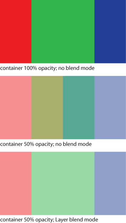
The top of Figure 9-7 shows a movie clip that contains three additional movie clips: two adjacent squares, red and blue, and a green square of the same dimensions centered on top of the underlying red and blue squares. If you were to apply a 50-percent alpha value to the parent movie clip, you might expect the parent movie clip opacity to be reduced by 50 percent, producing a lighter version of exactly what you saw on the stage. Unfortunately, ActionScript effectively goes into the parent clip and applies a 50-percent alpha reduction to each of the children individually.
The result, shown in the middle of Figure 9-7, is what you’d expect to see when applying a 50-percent alpha value to each square. However, when you want the entire container to fade, the default behavior produces an unpleasant effect. Because each of the squares is partially transparent, their colors blend, creating four bands. Left to right, the first is 50-percent red, the second is 50-percent green overlapping 50-percent red, the third is 50-percent green overlapping 50-percent blue, and the fourth is 50-percent blue.
When applying the Layer blend mode, however, the children of the parent movie clip are composited together as a single item and the alpha value is correctly applied to the container, not separately to each child within. As a result, you see the expected appearance of the original three colors all at 50 percent, as seen in the bottom of Figure 9-7.
Note
The blend_mode_layer.fla source file includes an interactive example toggling the application of the Layer blend mode to the three color boxes, as seen in Figure 9-7.
Alpha and Erase
Layer mode also facilitates the use of two more blend modes, Alpha and Erase. The functionality of each is straightforward. Given a foreground display object with alpha data, such as a movie clip with a partially transparent PNG inside, the two modes behave this way: Alpha knocks out a background element using the foreground element’s alpha channel, and Erase does the opposite, knocking out the background using the nontransparent pixel data of the foreground element. The effects of each can be seen in Figure 9-8. The overlying image is an opaque star on a transparent background. The white areas are actually missing from the underlying image, showing the stage beneath.

The important item to note, however, is that these effects work only when applied to display objects that are inside a display object container (such as a movie clip) and only when the Layer blend mode is applied to the container. The child elements must be composited together first for the effect to be visible.
In other words, if you used the same movie clip with semitransparent star PNG therein, and placed it on top of the same background beach image on the stage (rather than inside a movie clip), the beach image would not be affected even if the Alpha or Erase blend modes were applied to the star. Instead, it would cause the foreground element to disappear altogether.
Note
Push Yourself: Try to apply what you’ve learned and create a dynamic version of the example described in the Alpha and Erase section of this chapter. The blend_mode_alpha_erase_assets.fla source file contains the beach and star images. After giving this a try, look at the blend_mode_alpha_erase.fla source file. It includes an interactive example toggling the Alpha and Erase blend modes shown in Figure 9-8.
Using Blend Modes with BitmapData Instances
Blend modes can also modify other ActionScript objects, including instances of the BitmapData class. Earlier, we created a drawing program that used brush and eraser tools to paint on a canvas. In that simple example, the eraser tool was nothing more than a brush set to the color of the canvas, giving the illusion of erasing what you painted.
However, the draw() method used in that example takes, as its fourth argument, a blend mode, and we can use the Erase blend mode to erase brushstrokes instead of paint over them. Remember that the Erase blend mode uses the foreground content to erase the background content. In the example paint program, this means it will use the eraser tool pixels to erase the bitmap data of the canvas.
Note
The third parameter of the draw() method is used to transform the color of the bitmap data, which is not a part of this example. However, to use the fourth parameter, arguments for the first three parameters must be provided. The first is mandatory, and is the BitmapData instance we’re drawing. The second is optional, and is the transform matrix we’re using. The third is a colorTransform instance, which we aren’t using. In its place, we send in the parameter’s default value, null. Supplying these three values then allows us to provide the fourth value, our blend mode.
The following modification to the earlier example is found in the paint_tool_erase.fla source file. All we have to do is replace the use of the single draw() method in the prior script, at line 44, with a conditional statement. The conditional checks to see if the current tool is the brush. If so, it uses the same code as the previous example, drawing into the canvas bitmap data without using a blend mode (line 45). However, if the current tool is not the brush (which means the user is erasing content) the modified draw() method is used, with the Erase blend mode (lines 47 and 48).
1functiononLoop(evt:Event):void{ 2 tool.x=mouseX; 3 tool.y=mouseY; 4if(mouseIsDown) { 5if(tool == brush) { 6 bmd.draw(tool, tool.transform.matrix); 7 }else{ 8 bmd.draw(tool, tool.transform.matrix,null, 9BlendMode.ERASE); 10 } 11 } 12 }
Bitmap Filters
Filters have been a mainstay of graphics editing programs for years, adding special effects to images and illustrations with a minimum of effort. ActionScript has a number of filters for your number-crunching manipulation. Although there are no official classifications for filters, we’ve divided the filters we discuss into two sections: basic and advanced. Using Adobe Photoshop for comparison, basic filters are like Layer Styles—quick, easy-to-apply effects with limited functionality—and advanced filters are more robust and are more like the features found in Photoshop’s Filters menu.
Basic Filters
A good place to start when learning how to control filter effects with code is with a subset of filters found both in Flash Professional’s Properties panel and in their own ActionScript classes. These filters include DropShadow, Blur, Glow, Bevel, GradientGlow, and GradientBevel. This convenient overlap lets you play around with Flash Professional’s interface to see how various properties affect the appearance of the filter. You can then apply that understanding to your code settings later on. The advantages to using ActionScript over the Flash Professional interface include the ability to apply changes dynamically at runtime and reuse your code more easily.
Note
There’s no class in the flash.filters package for the Adjust Color filter found in Flash Professional’s Properties panel. However, Flash Professional users can use the AdjustColor class found in the fl.motion package. If you’re not using Flash Professional, advanced filter classes that appear a little bit later in the chapter can mimic Adjust Color’s filter results.
For the most part, the properties of the ActionScript filter classes correlate closely with the properties found in the Properties panel for the same filter, providing a smooth transition to ActionScript without much effort. Let’s use the DropShadowFilter class in the next example, to create button artwork without custom graphics.
Creating dynamic button art with the DropShadowFilter
The following script, found in the drop_shadow_button.fla source file, simulates a two-state button by using a drop shadow. At rest, the button has a small drop shadow, but when a user clicks the button, the drop shadow is removed as if the button is being pressed down to the screen. This effect is shown in Figure 9-9.
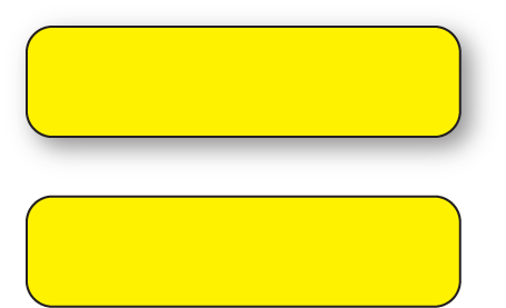
DropShadowFilter applied (above) and removed (below) to simulate the pressing of a raised buttonThe script begins by creating the drop shadow filter. Once created, it can be applied to objects at any time. An instance of the aptly named class is created in line 1. Individual properties are then set in lines 2 through 4. In this case, the degree of blur in the x and y directions is set to 10, and the opacity of the shadow is set to 60 percent. Other properties, including the angle of the shadow and its distance offset from the display object, use their default values.
Lines 6 through 11 use the Graphics class discussed in Chapter 8 to create a basic, yellow rectangle with rounded corners and add it to the display list. Line 13 is where the shadow is applied. The display object property, filters, accepts an array of filter instances so that more than one filter can be applied. In this example, only DropShadowFilter is used so only the ds filter instance is placed into the array. At this point, the application of the filter is complete, and the sprite is added to the display list in line 14. However, this example changes with mouse interaction, so let’s look at its interactive elements in the next code block.
1vards:DropShadowFilter=new DropShadowFilter(); 2 ds.blurX= 10; 3 ds.blurY= 10; 4 ds.alpha= 0.6; 5 6varsp:Sprite=new Sprite(); 7varg:Graphics= sp.graphics; 8 g.lineStyle(1, 0x000000); 9 g.beginFill(0xFFFF00, 1); 10 g.drawRoundRect(0, 0, 200, 50, 20); 11 g.endFill(); 12 13 sp.filters= [ds]; 14addChild(sp);
Because we went the simple route of using a sprite for our interactive element (rather than building a multistate button with the SimpleButton class, as seen in the applied example at the end of Chapter 8), we need to set the buttonMode property of the sprite to true in line 15. This won’t create the up, over, and down states of a button symbol, but it will provide visual feedback by changing the cursor to the hand cursor when over the sprite.
The listeners in lines 16 through 18 trigger functions based on mouse behavior. The mouse down listener function, onDown() (lines 20 to 22) removes the drop shadow effect from the sprite by clearing the filters array. Both the mouse up and mouse out listeners point to the onUp() function in lines 23 to 25, which repopulates the filters array with the drop shadow. This restores the elevated “up” appearance to the sprite.
Note
For information about creating arrays with bracket syntax ([]), see Chapter 2.
15 sp.buttonMode=true; 16 sp.addEventListener(MouseEvent.MOUSE_DOWN, onDown,false, 0,true); 17 sp.addEventListener(MouseEvent.MOUSE_UP, onUp,false, 0,true); 18 sp.addEventListener(MouseEvent.MOUSE_OUT, onUp,false, 0,true); 19 20functiononDown(evt:MouseEvent):void{ 21 sp.filters= []; 22 } 23functiononUp(evt:MouseEvent):void{ 24 sp.filters= [ds]; 25 }
Another way to handle this task would be to leave the ds filter active, but change some of its properties. For example, rather than eliminating the shadow, you could reduce its distance value when the button is pressed. When the shadow appears closer to the object, the object’s virtual elevation appears to be reduced.
Note
Filters can be used in creative ways. If you wanted to simulate casting a shadow from a moving light source, you could vary the distance, angle, and alpha values of the DropShadowFilter. See the “Animating Filters” post at the companion website, http://www.LearningActionScript3.com, for more information.
Using the BlurFilter to create an airbrush
With just a couple of lines of additional code, you can turn the brush from the drawing tool developed previously in this chapter into an airbrush. The following ActionScript excerpt shows new code in bold, and can be found in the paint_tool_erase_blur.fla source file. The first new line (30) creates an instance of the BlurFilter that blurs 40 pixels in the x and y direction. The second new line (39) applies the filter to the current tool. Figure 9-10 shows the result of softening the brush and eraser with these modifications.
26 canvas.addEventListener(MouseEvent.MOUSE_DOWN, 27 onDown,false, 0,true); 28 canvas.addEventListener(MouseEvent.MOUSE_UP, onUp, 29false, 0,true); 30 canvas.addEventListener(Event.ENTER_FRAME, onLoop, 31false, 0,true); 32 33varblur:BlurFilter=newBlurFilter(40, 40); 34 35functiononDown(evt:MouseEvent):void{ 36 mouseIsDown =true; 37if(evt.shiftKey) { 38 tool = eraser; 39 }else{ 40 tool = brush; 41 } 42 tool.filters= [blur]; 43 }

Advanced Filters
A number of more advanced ActionScript filters allow you to mimic some of the special effects features in pixel-editing applications like Photoshop. We’ll focus on the convolution, displacement map, and Perlin noise filters in this section, and then group a trio of color filters together in the following section.
Convolution filter
Convolution filtering is typically a part of many visual effects in most, if not all, pixel-editing applications. Photoshop offers direct access to a convolution filter (renamed to Custom some years ago, and found in the Filters✓Other menu), but usually the filter works quietly behind the scenes.
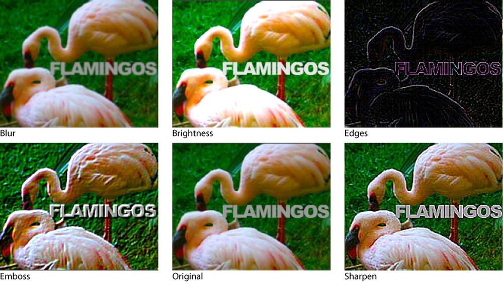
Put simply, a convolution filter calculates pixel color values by combining color values from adjacent pixels. Combining these colors in different ways (using different values in the matrix) produces a wide variety of image effects. These effects include, but are not limited to, blurring, sharpening, embossing, edge detection, and brightness.
Using the filter effectively requires at least a working knowledge of matrices so, if you haven’t read Chapter 8, do so now. Although still a matrix, visualized as a grid of numbers, the ConvolutionFilter doesn’t use the same matrix format discussed in Chapter 8. Instead, you can define any number of rows and columns in a convolution matrix, and the structure of the matrix determines how each pixel is affected.
Unless you plan to delve deeply into writing your own filters, you probably don’t need to learn the algorithms behind how a convolution matrix works. In most circumstances, you’ll use an existing matrix for a specific effect and use experimentation to determine a satisfactory setting.
To give your experimenting some focus, let’s look at three parts of the matrix: the center grid element, the grid symmetry, and the sum of all grid elements. Consider a 3 × 3 matrix. The center value in the matrix represents the current pixel (all pixels in an image are analyzed), while the remaining elements are the eight adjacent pixels. The numbers in each matrix position determine how the color values of that pixel affect the current pixel. The basic idea is that each of the nine pixels is given a weight, or importance, that affects how they are altered.
A convolution matrix of all zeros will turn an image black because no color values are used for any pixel, including the current pixel in the center of the grid. Using a 1 in the center of an all-zero grid won’t change the image because the current pixel is unchanged (default value of 1), and no color values from surrounding pixels are used. Placing a 2 in the center of an all-zero grid will brighten the image because no colors from surrounding pixels are used, but the weight of the color values of the current pixel are increased.
The ConvolutionFilter constructor appearing on line 8, 14, and 20 in the following code example requires two parameters, the number of rows and the number of columns. A third, optional parameter is the matrix used to affect the image. If no matrix is furnished a default (no change) matrix is used. Applying a default matrix allows you to remove any changes made by prior convolution filters, as seen in the event listener that follows. This code is found in the convolution_filter_basics.fla source file.
1varblack:ConvolutionFilter; 2varnoChange:ConvolutionFilter; 3varbrightness:ConvolutionFilter; 4 5varblackArr:Array= [0, 0, 0, 6 0, 0, 0, 7 0, 0, 0]; 8 black =new ConvolutionFilter(3, 3, blackArr); 9 mc0.filters= [black]; 10 11varnoChangeArr:Array= [0, 0, 0, 12 0, 1, 0, 13 0, 0, 0]; 14 noChange =new ConvolutionFilter(3, 3, noChangeArr); 15 mc1.filters= [noChange]; 16 17varbrightnessArr:Array= [0, 0, 0, 18 0, 2, 0, 19 0, 0, 0]; 20 brightness =new ConvolutionFilter(3, 3, brightnessArr); 21 mc2.filters= [brightness]; 22 23stage.addEventListener(MouseEvent.CLICK, onClick, 24false, 0,true); 25 26functiononClick(evt:MouseEvent):void{ 27for(vari:int= 0; i < 3; i++) { 28varmc:MovieClip=MovieClip(getChildAt(i)); 29 mc.filters= [noChange]; 30 } 31 }
Now let’s focus on the symmetry of the surrounding grid elements. The remainder of the code in this section is found in the convolution_filter_more.fla source file, and demonstrates centralizing the filter creation into a function called convFilter() to reduce repeating code. The function appears at the end of the discussion so you can focus on the matrices we’re discussing.
The embossUp example uses reduced values for the three pixels to the upper left of the current pixel, and increased values for the three pixels to the lower right of the current pixel. The result is a traditional embossing effect (see Figure 9-11). By contrast, the embossDown example reverses this effect, seemingly stamping into the image.
32varembossUp:Array= [−1, −1, 0, 33 −1, 1, 1, 34 0, 1, 1]; 35 convFilter(mc0, embossUp); 36 37varembossDown:Array= [1, 1, 0, 38 1, 1, −1, 39 0, −1, −1]; 40 convFilter(mc1, embossDown);
As our third area of interest, we want to focus on the fact that overall image brightness is affected by the sum of all elements in the matrix. In each of the prior examples, all the matrix elements add up to 1, except brighter (which adds up to 2) and black (which adds up to 0). The following example is a matrix that uses the left, top, right, and bottom adjacent pixel color values to affect the current pixel. The result is a blurring effect. However, a dramatic brightening of the image occurs because the sum of the matrix elements is 5, not 1. The affected image is five times brighter.
If this is not desired, you can compensate by using an optional fourth parameter of the ConvolutionFilter class, called a divisor. The sum of the matrix will be divided by this value and the result will affect the brightness. If the result is 1, the brightening effect of the matrix will be eliminated. The first filter instance here uses only the first three parameters without compensating for brightness. The second instance adds the divisor as the fourth parameter, bringing the brightness back to the original state, leaving only the blur effect.
41varblurBright:Array= [0, 1, 0, 42 1, 1, 1, 43 0, 1, 0]; 44 convFilter(mc2, blurBright); 45 46varblurOnly:Array= [0, 1, 0, 47 1, 1, 1, 48 0, 1, 0]; 49 convFilter(mc3, blurOnly, 5);
As a summary of what we’ve learned, we’ll look at how sharpen and find edges filters differ. The sharpen instance that follows uses negative values for the left, top, right, and bottom pixels, which is the opposite of blur and causes the pixels to pop. The sum of the matrix is 1, meaning there is no increase or decrease in brightness.
The edges instance uses the same values for the surrounding pixels, but the sum of the array is 0. This has a sharpening effect but reduces the brightness, leaving only the emphasized edges visible.
50varsharpen:Array= [ 0, −1, 0, 51 −1, 5, −1, 52 0, −1, 0]; 53 convFilter(mc4, sharpen); 54 55varedges:Array= [ 0, −1, 0, 56 −1, 4, −1, 57 0, −1, 0]; 58 convFilter(mc5, edges);
The function that applies these matrices differs from the prior source file in only one major respect: It provides for the use of the fourth optional parameter, divisor, to compensate for accumulated brightness.
59functionconvFilter(dispObj:DisplayObject, matrix:Array, 60 divisor:int=1):void{ 61varconv:ConvolutionFilter= 62new ConvolutionFilter(3, 3, matrix, divisor); 63 dispObj.filters= [conv]; 64 }
Perlin noise and displacement map
Two other very useful and entertaining effects supported by ActionScript are the Perlin noise generator and the displacement map filter. Perlin noise is widely used for generating naturalistic animated effects like fog, clouds, smoke, water, and fire, as well as textures like wood, stone, and terrain. Displacement maps are used to translate (or displace) pixels to add extra dimension to surfaces. They are commonly used to add realism to textures (such as a pitted or grooved surface) as well as distort images to appear as if seen through a refracting material like glass or water.
Note
Ken Perlin developed the Perlin noise algorithm while creating the special effects for the 1982 film Tron. At the time, the extensive use of effects in that film may have been cost-prohibitive using traditional multi-exposure film compositing techniques. Perlin noise was used to manipulate the near-constant computer-generated glows and shadings, among other effects. Mr. Perlin won an Academy Award for Technical Achievement in 1997 for his contributions to the industry.
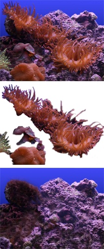
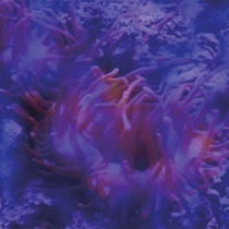
The following exercise, found in the perlin_displacement.fla source file, will create an animated Perlin noise texture that will then be used as the source for a displacement map. In our example, the Perlin noise will include random areas of blue, as shown in Figure 9-12. These blue areas will cause the displacement in a photo of a reef aquarium, and the combined effect will cause soft corals in the scene to undulate as if experiencing the effect of water currents.
The source material we’ll use is a picture of a reef aquarium, as seen in Figure 9-13. The sea life are the sole elements in a foreground image, and will be affected by the filters so that they will appear to be moving in the water current. The rock is in a separate background and will not be affected.

Perlin noise
The first step in building our aquarium simulation is to create a BitmapData object to contain the Perlin noise. Our image will cover the stage, so we’ll pass the stage width and height into the object to size it appropriately (line 1). Lines 3 and 4 create a bitmap using the bitmap data, and then add that bitmap to the display list. However, the lines are commented out because we do not want to see the Perlin noise in the final product. We need access only to the bitmap data to drive the displacement map. However, it’s often helpful to see the Perlin noise as you work so you can experiment with various settings. By uncommenting these lines, you can adjust the Perlin noise values until you’re satisfied with the effect, and then comment out these lines again when moving on to the displacement filter.
1varbmpData:BitmapData=new BitmapData(stage.stageWidth, 2stage.stageHeight); 3//var bmp:Bitmap = new Bitmap(bmpData);4//addChild(bmp);5//comment out lines 3 and 4 to see Perlin noise
The Perlin noise generator has a number of settings that will produce dramatically different results when adjusted. As we discuss these settings, we’ll reference natural phenomena, like water and smoke. We’ll first discuss the settings of the filter and then simply pass these settings into the perlinNoise() method later on in lines 30 through 32.
Lines 7 and 8 set the scale of the texture in the x and y directions. Think of this as influencing the number of waves you can see at one time in water. A very large scale might result in the look of a swelling sea, and a small scale might look like a babbling brook.
Line 7 determines the number of octaves in the texture, which are discreet layers of noise that function independently of each other. A single-octave noise will not be as complex as a multi-octave noise and, during animation, you can move a single-octave noise in only one direction at a time. You can create basic animations with single octaves, like the look of running water or, in our case, underwater current. But the ability to move each octave in a different direction makes multi-octave noise better suited for effects like colliding waves moving in multiple directions, or fire, or smoke.
Line 10 creates a random seed to influence the starting point for the creation of the texture. A random seed allows you to randomize the effect but also call back that same result by using the same seed at a later time. In our case, we only care about the randomization, so we’ll use a random number, between 0 and 100, for the seed as well.
Note
Perlin noise layers are called octaves because, like musical octaves, each one doubles the frequency of the previous octave, increasing detail within the texture. It’s also important to note that the processor power required to generate noise patterns increases with the number of octaves used.
6//perlin noise settings7varbaseX:Number= 50; 8varbaseY:Number= 50; 9varnumOctaves:Number= 1; 10varrandomSeed:Number=Math.random() * 100; 11varstitch:Boolean=true; 12varfractalNoise:Boolean=true; 13varchannelOptions:Number=BitmapDataChannel.BLUE; 14vargrayScale:Boolean=false; 15varoffsets:Array=new Array(new Point());
Line 11 determines whether the edges of the area defined when creating the noise pattern are stitched together in an attempt to create a seamless tile. When creating static textures, this “stitching” is not usually needed, but it’s recommended when animating the effect.
Whether fractal noise or turbulence techniques are used when generating the effect is determined by line 12. Fractal noise (used when the fractalNoise property is true) generates a smoother effect; turbulence (used when the fractalNoise property is false) produces more distinct transitions between levels of detail. For example, fractal noise might be used to create a terrain map of rolling hills or an oceanscape, and turbulence might be better suited to a terrain of mountains or crevices in a rock.
Line 13 chooses which channels of bitmap data are used when generating the texture: red, green, blue, and/or alpha. These can be indicated by constants from the BitmapDataChannel class or with integers. You can also use a special operator called the bitwise OR operator (|) to combine channels to create multicolor effects or combine color with alpha. For example, combining alpha with noise can create fog or smoke with transparent areas through which a background can be seen.
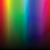
In this exercise, because we are generating a pattern only to provide data for a displacement map, we need only one channel. (Blue was chosen arbitrarily.) However, experimenting with the Perlin noise settings can make it difficult to visualize the texture’s effect. To improve these efforts a bit, you can add alpha data to the mix, so you can see the underlying image through the pattern. Figure 9-14 shows the visible noise texture and the reef beneath it. In our finished example, the anemones will be displaced to a greater degree where blue is more visible.
To see the background image as you experiment with the noise settings, you just have to add an alpha channel to the channelOptions property. To do this, replace line 13 with this:
13varchannelOptions:Number=BitmapDataChannel.BLUE|BitmapDataChannel.ALPHA;
The grayscale parameter in line 14 desaturates the texture so it generates only grays. In our exercise, the texture won’t be visible, so this isn’t relevant, but it’s ideal when visible fog or smoke is required.
Finally, line 15 uses an array of offset points, one for each octave, to control the location of the noise pattern generated. We need only one octave in this example, so this is a single-item array. Because the texture will not be visible, its starting point is arbitrary, so we’ll use a default point of (0, 0). During animation, we’ll alter the position of this point to move the pattern.
You’ve now set all the values required to create a Perlin noise texture. If you want to see the noise before moving on to the next section, look at the perlin_noise_only.fla source file. Later, we’ll animate these values by changing the offset values upon every enter frame event. First, however, we need to set up the displacement map settings.
Displacement map
The displacement map filter is a bit simpler. Lines 18 and 19 of the script that follows determine which color channel will affect the distortion in each direction. We used the blue channel when creating our Perlin noise texture, so we’ll use the same channel here.
Next, lines 20 and 21 set the scale of displacement in the x and y directions. Think of these values as the size of the waves when looking through water, or the degree of refraction when looking through glass, in each direction.
16//displacement map settings17vardisplaceMap:DisplacementMapFilter; 18varcomponentX:uint=BitmapDataChannel.BLUE; 19varcomponentY:uint=BitmapDataChannel.BLUE; 20varxScale:Number= 10; 21varyScale:Number= 10; 22 displaceMap =new DisplacementMapFilter(bmpData,new Point(), 23 componentX, componentY, xScale, yScale, 24DisplacementMapFilterMode.CLAMP);
Finally, lines 22 through 23 determine how the edges of the displacement map will behave. When set to clamp, any displacement will be confined by the edges of the source data. If wrap, is used, the distortion will wrap around from edge to edge. The wrap option is great for tiled patterns but not useful for affecting a realistic image of a recognizable object. You don’t want to see the top of a person’s head appearing beneath their feet as a displacement wraps from top to bottom edge.
Now that our settings are complete, we create the DisplacementMapFilter in lines 22 through 24. The source for the displacement data is the same BitmapData object that is being affected by the Perlin noise pattern, so the degree of displacement will be determined by that bitmap data, passed into the class in the first parameter. The second parameter is the map point—the location at which the upper-left corner of the displacement map filter will be applied. This is useful for filtering only a portion of the image. We want to filter the entire image, however, so we’ll pass in a default point to begin filtering at (0, 0). The remainder of the parameters correspond directly to the settings previously created.
Animating the effect
To animate the Perlin noise, and therefore the displacement map effect, we start with a listener that triggers the onLoop() function upon every enter frame event. The first thing the function does is update the offset point for the Perlin noise octave, seen in lines 28 and 29. This example sets the offset point of the octave, not the location of a display object (see the adjacent note for more information). Lines 28 and 29 move the first octave (the only octave used in our example) up and to the right, 2 pixels in each direction.
Note
Animating an octave with the offset property is not the same as moving a display object. Instead, think of adjusting the offset position of an octave as adjusting that octave’s registration point.
If you move a movie clip five pixels in the x and y directions, it will move down and to the right. However, if you adjust the movie clip’s registration point, down and to the right, the clip won’t move on stage, but its contents will move up and to the left.
With each change to the offset point, the perlinNoise() method is called (line 30), applying all the previously set parameters along with the offset update. Finally, with the call of the Perlin noise method, the DisplacementMap filter source data is updated, so the DisplacementMap filter must be reapplied to the display object in line 33.
25//enter frame update of both filters26addEventListener(Event.ENTER_FRAME, onLoop,false, 0,true); 27functiononLoop(evt:Event):void{ 28 offsets[0].x-= 2; 29 offsets[0].y+= 2; 30 bmpData.perlinNoise(baseX, baseY, numOctaves, randomSeed, 31 stitch, fractalNoise, channelOptions, 32 grayScale, offsets); 33 tank_mc.filters= [displaceMap]; 34 }
Color Effects
You can apply color effects using ActionScript in multiple ways, and we’ll look at three. The first is relatively straightforward: Alter the emphasis of individual color channels (red, green, blue, and alpha) in an image using the ColorTransform class. The second is a more powerful technique that uses the ColorMatrixFilter to apply a detailed matrix to simultaneously change all color and alpha channels. The last method discussed is the simplest, using the Color class to apply a tint to a display object.
The ColorTransform Class
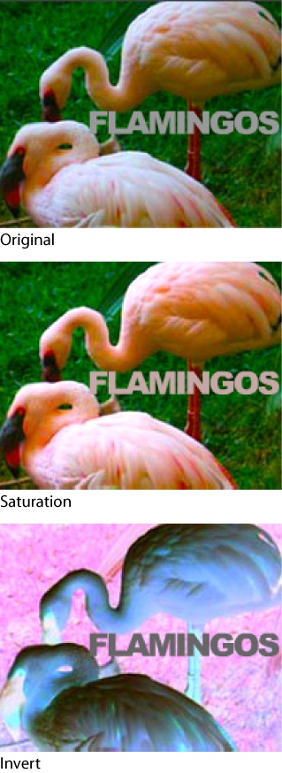
Although we’ll focus exclusively on color, you can use the ColorTransform class to adjust the alpha channel as well as the individual color channels of a display object or BitmapData object. In the examples that follow, we’ll be using the class to invert an image (create a color negative) and apply a simple saturation effect.
The class offers two ways to change color. First, you can multiply a color channel to increase or decrease its effect. For example, you can double the weight of the color by using a multiplier of 2, and you can reduce the weight of the color by half by using 0.5 as a multiplier. Second, you can offset a color channel from −255 to 255. For example, assuming a default multiplier of 1 (no change from the multiplier), an offset value of 255 would maximize the red channel, 0 would apply no change, and −255 would remove all red from the image.
The following code, found in the color_transform.fla source file, manipulates three movie clips instantiated as mc0, mc1, and mc2. Lines 1 through 10 show the default ColorTransform instance, which makes no change to the source material. Also, by using this default configuration (with a multiplier of 1 and an offset of 0 on each channel), you can effectively reset any prior color transformation. Despite the example’s focus on color, we’ve included alpha multiplier and offset values to show the complete syntax of a reset.
Note that the ColorTransform class is not a filter, so it’s not applied to the filters property of a display object. Instead, the color transformation is applied to the colorTransform property of a display object’s transform object (line 10). Similar to the filtering process, however, every time a change is made to the color transformation, it must be reapplied to the colorTransform property.
Lines 12 through 19 provide for an increase in saturation. The offset values of all colors are unchanged, but the color multipliers increase the color for each channel. To emphasize the image, the values used increase red more than green and blue. This effect can be seen in the “Saturation” example in Figure 9-15. You could also partially desaturate an image using the same technique but applying a multiplier value of less than 1 to each color channel.
Finally, lines 21 through 28 invert all color in the image. The multiplier for all color channels is set to −1, which effectively turns the image black, and then the offset values are set to full to revert back to color. This effect can be seen in the “Invert” example from Figure 9-15.
1varnoChange:ColorTransform=new ColorTransform(); 2 noChange.redOffset= 0; 3 noChange.greenOffset= 0; 4 noChange.blueOffset= 0; 5 noChange.alphaOffset= 0; 6 noChange.redMultiplier= 1; 7 noChange.greenMultiplier= 1; 8 noChange.blueMultiplier= 1; 9 noChange.alphaMultiplier= 1; 10 mc0.transform.colorTransform= noChange; 11 12varsaturation:ColorTransform=new ColorTransform(); 13 saturation.redOffset= 0; 14 saturation.greenOffset= 0; 15 saturation.blueOffset= 0; 16 saturation.redMultiplier= 1.3; 17 saturation.greenMultiplier= 1.1; 18 saturation.blueMultiplier= 1.1; 19 mc1.transform.colorTransform= saturation; 20 21varinvert:ColorTransform=new ColorTransform(); 22 invert.redOffset= 255; 23 invert.greenOffset= 255; 24 invert.blueOffset= 255; 25 invert.redMultiplier= −1; 26 invert.greenMultiplier= −1; 27 invert.blueMultiplier= −1; 28 mc2.transform.colorTransform= invert;
The ColorMatrixFilter Class
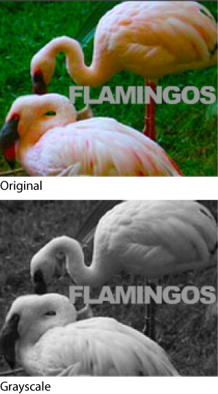
The next color effect uses the ColorMatrixFilter class. This class uses a 4 × 5 matrix to transform red, green, blue, and alpha values of the image, and can be used to create advanced hue, saturation, and contrast changes, among other effects. The following example demonstrates using luminance constants to desaturate an image to create a color grayscale.
The identity matrix (the default matrix, as discussed in Chapter 8) for the ColorMatrixFilter class is as follows:
Rs, Gs, Bs, As, Os
Rnew = 1, 0, 0, 0, 0,
Gnew = 0, 1, 0, 0, 0,
Bnew = 0, 0, 1, 0, 0,
Anew = 0, 0, 0, 1, 0
The rows represent the sum of changes in red, green, blue, and alpha values for each pixel. The first four columns are the multipliers for red, green, blue, and alpha values of the source (s), and the fifth column is the offset value for each row. The identity matrix shows a default multiplier of 1 and offset of 0 for each color channel, and no change to the other source color multiplier or offset values for that channel—that is, Rnew equals Rs, Gnew equals Gs, and so on.
Note
Luminance is the amount of light that is reflected or emitted by a color. In lay terms, luminance is brightness (which is more of a human perception than a measured quantity). NTSC broadcast luminance constants (TV grayscale) published in 1954 were replaced by values better tuned to CRT monitors and computer displays.
For many years, Paul Haeberli’s luminance vectors of 0.3086 for red, 0.6094 for green, and 0.0820 for blue, published in 1993, were used for color grayscale. Recently, these values have been adjusted for HDTV standards and are now slightly different. Red has reduced slightly, and green and blue have increased slightly, over previous values. The current standard is 0.2126 for red, 0.7152 for green, and 0.0722 for blue. Experiment to see which combination you prefer.
By introducing changes to the other color values, the appearance of each pixel will change. A good way to make this clear is to demonstrate the creation of a color grayscale image. When creating the new red value for a pixel, instead of using a multiplier of 1 for red and 0 for green and blue, you can use a partial value of 1 for all colors (with no change in alpha or offset). There will be no change in brightness because the sum of each row will still be 1. The alpha row receives no change to R, G, or B values, and the standard alpha multiplier of 1 is used with no offset.
The only question is, what partial values should be used for each color? Knowing that hexadecimal values of gray are created with equal values of each color (0x666666, for example), it’s common to see a value of 0.33 used for each R, G, and B component of every pixel. However, it turns out that unequal values of red, green, and blue combine to create better grayscale images. We can take advantage of prior research to achieve color grayscales that are more pleasing to the eye, using what are known as luminance constants—constant red, green, and blue brightness values used for color calibration.
By applying these constants to the source R, G, and B values, the new red, green, and blue values for each pixel will be optimized for grayscale display (Figure 9-16). The newly created matrix is passed to the filter constructor (line 8), and the result is applied to the filters array of the display object (line 12). The following code is found in the color_matrix_filter.fla source file.
1//ITU-R BT.709-5 Parameter Values for the HDTV2// Standards for Production, 20023varlumRd:Number= .2126; 4varlumGr:Number= .7152; 5varlumBl:Number= .0722; 6 7vargrayscale:ColorMatrixFilter= 8new ColorMatrixFilter([lumRd, lumGr, lumBl, 0, 0, 9 lumRd, lumGr, lumBl, 0, 0, 10 lumRd, lumGr, lumBl, 0, 0, 11 0, 0, 0, 1, 0]); 12 mc1.filters= [grayscale];
The Color Class
The last color manipulation is the simplest. It uses the Color class, from the fl.motion package to set the tint of a display object. The tint is set the same way line and fill styles are set using the Graphics class. Two parameters, color and alpha, are used to define the tint. Once the tint is created, it’s applied to the colorTransform property of the display object’s transform object, as in previous examples.
The following code is found in the set_tint.fla source file:
1import fl.motion.Color; 2 3varblueTint:Color=new Color(); 4 blueTint.setTint(0x0000FF, 1); 5 mc.transform.colorTransform= blueTint;
Note
Discussed in Chapter 8, the Color class was written to support converting timeline animations into ActionScript and is only available to Flash Professional users. However, we have reproduced a subset of these features, to support the material covered in this book, in the com.learningactionscript3.color.ColorUtils class. This will allow users of other ActionScript editors to use the scripts in this book with minor modification. The class is included in the source material for this chapter, and its use in sample source code for Chapter 8 includes notes on its use.
Image Encoding and Saving
Now that you know how to create bitmap data, let’s talk about how to save it! We’ll discuss encoding a BitmapData object and saving the image as a JPG. At the end of the chapter, you’ll see how to add encoding and saving to our ongoing painting application, as well as save to PNG format, complete with transparency.
The encoding process involves sending the bitmap data to an image encoding class. Fortunately, Adobe provides both JPG and PNG encoders as part of Adobe’s AS3 Core Library. At the time of this writing, information can be found at https://github.com/mikechambers/as3corelib, where you can download the library.
Note
An ActionScript 3.0 package called ZaaIL, developed by Aaron Boushley and Nate Beck of ZaaLabs, adds support for 40 additional image formats! See http://www.zaalabs.com/2010/04/introducing-zaail-40-image-format-support-for-flash/ for more information.
The saving portion of the exercise is accomplished using the FileReference class. This class allows you to upload and download files. Some features, including the save() method for saving to your hard drive, require Flash Player 10.
Note
When using a Flash Player 10–specific feature, be sure your file is set to publish to Flash Player 10 in the File✓Publish Settings✓Flash✓Player menu. (Flash Professional CS5 users can get to this setting immediately by clicking the Profile✓Edit button in the Publish section of the Properties panel.)
Note
The companion website includes information about using a server and PHP to accomplish the same goal in Flash Player 9. See the post “Saving Data in Flash Player 9 Using PHP” for more information.
Saving JPG Images
The heavy lifting of this exercise is performed during the encoding process by Adobe’s image encoder classes. The inner workings of these classes are a bit outside the scope of this book, but they’re very easy to use. The following script is found in the encode_and_save_jpg.fla source file, and it demonstrates the handy feature of taking a screen capture of everything on the stage. We’ll review Chapter 8 by drawing a button dynamically and adding it to the stage. Clicking that button will copy anything on the stage into a BitmapData instance, and then provide a prompt to save that image as a JPG. Later on, we’ll use a button to save the contents of a preexisting BitmapData instance—namely, the output of the paint program we developed earlier in this chapter.
This exercise starts routinely with line 1 importing the JPGEncoder class, and lines 3 through 11 drawing a button and adding it to the display list. Notice that lines 8 and 9 center the button by determining the horizontal and vertical center of the stage, and line 10 sets the buttonMode property of the sprite to true to enable hand cursor feedback when rolling over the sprite.
1importcom.adobe.images.JPGEncoder; 2 3varsaveBtn:Sprite=new Sprite(); 4varg:Graphics= saveBtn.graphics; 5 g.beginFill(0x990000, 1); 6 g.drawCircle(0, 0, 40); 7 g.endFill(); 8 saveBtn.x=stage.stageWidth/2; 9 saveBtn.y=stage.stageHeight/2; 10 saveBtn.buttonMode=true; 11addChild(saveBtn);
Note
See Chapter 8 if you need to review drawing vectors with the Graphics class.
Lines 12 and 13 add a mouse click event listener to the button, which calls the function in lines 14 through 24 when the button is clicked. Lines 15 and 16 create a BitmapData object the size of the stage, and line 17 draws into the object everything on the stage, effectively taking a screen shot of the stage.
Line 19 creates an instance of the JPGEncoder class, and passes an image quality setting of 100 into the constructor when doing so. If no value is passed into the class during instantiation, a 50-percent quality setting is used. Line 20 encodes the bitmap data into bytes that can be understood as a JPG. It also stores the bytes in a special array called a ByteArray. A ByteArray is a heavily optimized array with its own properties and methods for reading and writing data at the byte level.
Finally, line 22 creates an instance of the FileReference class, and line 23 invokes the save() method from this instance. In doing so, it passes in the bytes for the JPG and a default file name. The user’s operating system prompts for a location to save the file and the JPG is written to your local directory of choice.
Note
Prior to Flash Player 10.1, saving a file using the FileReference class required active involvement, such as a mouse click, from the user. You can’t invoke the save() method from a timer or enter frame event, for example, because that is considered a passive experience from the viewpoint of the user. This has been relaxed in Flash Professional CS5.
12 saveBtn.addEventListener(MouseEvent.CLICK, onSaveImage, 13false, 0,true); 14functiononSaveImage(evt:Event):void{ 15varstageCapture:BitmapData= 16new BitmapData(stage.stageWidth,stage.stageHeight); 17 stageCapture.draw(stage); 18 19varjpgEncoder:JPGEncoder =newJPGEncoder(100); 20varjpgBytes:ByteArray= jpgEncoder.encode(stageCapture); 21 22varfileRef:FileReference=new FileReference(); 23 fileRef.save(jpgBytes,"stageCapture.jpg"); 24 }
Adding Functionality to Your Color Picker

Now it’s time to exercise the gray cells and put what you’ve learned into practice. The first example makes the color picker art you created in Chapter 8 functional. In the process, you’ll learn how to get and set pixel color values in a BitmapData instance. Then we’ll end with an exercise that uses many of the skills you’ve developed over the past few chapters. We’ll expand the drawing application you created by adding the color picker to change the color of your brush. We’ll also use the RoundRectButton class from Chapter 8 to create a button that triggers a save method, saving your artwork to your hard drive in PNG format.
Getting and Setting Pixels
In Chapter 8, we created the visual component of a color picker (shown in Figure 9-17), but didn’t add any functionality to the exercise. In this chapter, we’ll expand this class-based example and create a ColorPickerCustom class (named as such to differentiate it from the ColorPicker component in Flash Professional). This class will add an instance of the ColorPickerGraphics class you created in Chapter 8 to serve as the color graphic in the picker. We’ll also add a simple text display and a “current color” chip to the picker, and then show you how to get and set pixels using methods of the BitmapData class. The class is found in the book code library, at com/learningactionscript3/color/ColorPickerCustom.as, and we’ll put it to use in the next section.
Lines 1 through 10 define the package and import all the classes required by this class. Lines 12 through 18 declare the class (which extends MovieClip so you can easily treat the picker as a display object) and declare a small number of variables. Lines 14 and 15 contain the picker (_pickerArt) and a BitmapData instance (_bmd) that will contain the pixel data from the picker. This will allow us to get the color value of a pixel during the actual color picking process.
Note
ColorPickerGraphics, the display portion of the color picker exercise created in Chapter 8, is in the same directory as this class, so your new code will function without importing that class. However, doing so allows you to see all class dependencies at a glance.
The _col variable in line 16 will hold the picked color, and the _tf variable in line 17 will contain a text field that we’ll use to display the color value in string hexadecimal notation (#FFFFFF rather than 0xFFFFFF). The final variable, _chip, in line 18, will contain a movie clip that we’ll tint to match the selected color. The text and color chip will provide valuable feedback for the user when picking colors.
1packagecom.learningactionscript3.color { 2 3import flash.display.BitmapData; 4import flash.display.Graphics; 5import flash.display.MovieClip; 6import flash.events.MouseEvent; 7import flash.text.TextField; 8import flash.text.TextFieldAutoSize; 9import fl.motion.Color; 10importcom.learningactionscript3.color.ColorPickerGraphics; 11 12public classColorPickerCustomextends MovieClip{ 13 14private var_pickerArt:ColorPickerGraphics; 15private var_bmd:BitmapData; 16private var_col:uint= 0x000000; 17private var_tf:TextField; 18private var_chip:MovieClip;
Lines 20 through 50 make up the class constructor. Lines 21 and 22 create an instance of the ColorPickerGraphics class to create the spectrum artwork, and add it as a child of the new class instance. Lines 23 and 24 add a mouse click event listener to the picker art inside the class. The private method onClick() (lines 52 through 59) will be used for visual feedback inside the picker (setting the text and “current color” chip values) and to populate a class property with the selected color. What we do with that color will be determined outside the ColorPickerCustom class when the picker is put into use by a project. We’ll look at that process later in this section.
Lines 26 through 28 create a BitmapData instance the size of the picker art and draw the picker art into the bitmap data. Once we have the color spectrum in pixel data, we can retrieve the color values of a pixel clicked on by the mouse.
Note
In this example, no bitmap is created from the bitmap data or added to the display list. Because the spectrum art has already been stored in the _pickerArt property and added to the display list, we need only the BitmapData instance for accessing color data. It need not be a part of the display list.
Lines 30 through 37 create a text field to display the chosen color’s hexadecimal value. It’s the width of the picker art, 14 pixels tall, and positioned just under the picker art. Note its initial content of “#FFFFFF” (white) is in line 34. In a moment, we’ll also apply an initial white color to the selected color chip. In line 35, the field’s background (with a default color of white) is turned on so the picker won’t let the stage color show beneath the field. Also, line 36 disables mouse interaction so that the cursor won’t change into a text cursor upon rolling over the field and the text won’t be selectable.
Lines 39 through 45 draw a small movie clip using the Graphics class discussed in Chapter 8, to serve as the selected color chip. It’s white (set in line 41), 100 × 14 pixels (line 42) and is positioned just under the text field (line 44). Also, using the Graphics class, lines 47 through 50 draw a 1-pixel black border for the entire picker, as a finishing touch to the picker’s appearance.
19//class constructor20public functionColorPickerCustom() { 21 _pickerArt =newColorPickerGraphics(); 22addChild(_pickerArt); 23 _pickerArt.addEventListener(MouseEvent.CLICK, 24 onClick,false, 0,true); 25 26 _bmd =new BitmapData(_pickerArt.width, 27 _pickerArt.height); 28 _bmd.draw(_pickerArt); 29 30 _tf =new TextField(); 31 _tf.width= 100; 32 _tf.height= 14; 33 _tf.y= 100; 34 _tf.text="#000000"; 35 _tf.background=true; 36 _tf.mouseEnabled=false; 37addChild(_tf); 38 39 _chip =new MovieClip(); 40 var g:Graphics= _chip.graphics; 41 g.beginFill(0x000000); 42 g.drawRect(0, 0, 100, 14); 43 g.endFill(); 44 _chip.y= 114; 45addChild(_chip); 46 47varborder:MovieClip=new MovieClip(); 48 border.graphics.lineStyle(1, 0x000000); 49 border.graphics.drawRect(0, 0, 100, 128); 50addChild(border); 51 }
getPixel()
Three things happen within the class when the picker is clicked. First, the getPixel() method is used in lines 54 and 55 to retrieve the color value from the pixel at the mouse location. This color is stored in the private property _col. Second, line 56 places the hexadecimal value of the color into the text field, using the prependZeros() method in lines 67 through 75. We’ll cover that method in a moment. Finally, the setTint() method (line 59) is used to apply the selected color to the color chip, as discussed previously in the section The Color Class.
52//listener function53private functiononClick(evt:MouseEvent):void{ 54 _col = _bmd.getPixel(_pickerArt.mouseX, 55 _pickerArt.mouseY); 56 _tf.text= prependZeros(_col); 57 58varcol:Color=new Color(); 59 col.setTint(_col, 1); 60 _chip.transform.colorTransform= col; 61 }
At this point, the color picker is completely functional, but only as a self-contained widget. We can’t yet use the picker for its intended purpose, because the _col property is private, so we can’t retrieve the selected color from outside the class. Therefore, the last functionality we need to put in place is a getter, color, in lines 63 through 65, to provide access to the _col property.
62//getter for access to _col63public function getcolor():uint{ 64return_col; 65 }
Finishing the explanation of this class, the aforementioned prependZeros() method takes a numeric color value and converts it to a string for display in the picker’s text field. However, when converting to a string, leading zeros are dropped. As such, if blue was selected, a string converted from its hexadecimal value would read FF instead of the far more typical 0000FF equivalent. So we need to add the number of leading zeros required to fill out the color value.
The method starts with an empty string, zeros, in line 68, and then converts the numeric value to a string in line 69 using the toString() method. If we used this method without an argument, it would convert the number to decimal, or base 10. White, therefore, would appear as 16777215, which isn’t very useful for most people. By passing 16 into the method, it will convert the value to hexadecimal, or base 16. Using this argument, the result for white would be ffffff—acceptable, but not ideal. By using the toUpperCase() method, the string will be converted to uppercase and display as FFFFFF. All that remains is adding any necessary leading zeros and the preceding hash mark (#).
Because the hexadecimal color string we want has six characters, line 70 determines how many zeros are needed by subtracting the current length of the string from 6. Using blue (0000FF) as an example again, 6 minus 2 (for the two characters in FF) is 4, so we need 4 zeros. Lines 71 through 73 loop the determined number of times and build the zeros string. Finally, the return string is assembled by concatenating the hash mark, leading zeros, and color string.
66//text formatting for hex string display in picker67private functionprependZeros(hex:uint):String{ 68varzeros:String=""; 69varhexString = hex.toString(16).toUpperCase(); 70varcnt:int= 6 - hexString.length; 71for(vari:int= 0; i < cnt; i++) { 72 zeros +="0"; 73 } 74return"#"+ zeros + hexString; 75 } 76 } 77 }
Using the picker with setPixel()
Now that you know how to get the color values from a pixel, let’s do the reverse. To set the color values of a pixel in a BitmapData object, you need to again provide an x and y coordinate, but you also need to furnish the color you want the pixel to display. In the color_picker_set_pixel.fla source file, we’ll use the picker we just created to set the color of pixels in a small bitmap.
Lines 1 through 5 import the ColorPickerCustom class, instantiate the picker, place it at point (10, 10), and add it to the display list. Lines 7 through 12 create a 100 × 100–pixel black BitmapData object, create a bitmap from that data, position it just to the right of the picker, and add it to the display list. The enter frame event listener in lines 14 through 19 manipulates the bitmap data, which we’ll explain after the code.
1importcom.learningactionscript3.color.ColorPickerCustom; 2 3varcolorPicker:ColorPickerCustom =newColorPickerCustom(); 4 colorPicker.x= colorPicker.y= 10; 5addChild(colorPicker); 6 7varcanvasBmd:BitmapData=new BitmapData(100, 100, 8false, 0xFF000000); 9varcanvasBm:Bitmap=new Bitmap(canvasBmd); 10 canvasBm.x= 120; 11 canvasBm.y= 10; 12addChild(canvasBm); 13 14addEventListener(Event.ENTER_FRAME, onLoop,false, 0,true); 15functiononLoop(evt:Event):void{ 16varrndX:int=Math.random() * 100; 17varrndY:int=Math.random() * 100; 18 canvasBmd.setPixel(rndX, rndY, colorPicker.color); 19 }
Lines 16 and 17 of the listener select random pixel locations between 0 and 100, the size of the BitmapData instance. These values are then passed to the setPixel() method, along with the value from the color property of the picker. Figure 9-18 shows the file in action.
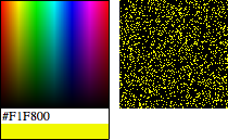
Note
The setPixel() method takes integer pixel values but ActionScript will automatically truncate a Number (lop off the decimal value) when passed into any object typed as an int.
If you want to get a better view of the pixels changing, add the following bold line to your script after line 11. This will scale the bitmap 300 percent, enlarging the pixels so they are easier to see. The source file already has this line in place, so you can compare your file with the source file, if you prefer.
10 canvasBm.y= 10; 11 canvasBm.scaleX= canvasBm.scaleY= 3; 12addChild(canvasBm);
Expanding Your Paint Program
This exercise picks up where our paint tool left off, and can be found in the paint_tool_erase_blur_pick_save_png.fla source file. At this point, the paint program can paint using a blue color and air brush effect, as well as erase what you create. We’re going to add the most recent color picker, to allow you to pick the color for your brush, and a custom button and image encoder to save your artwork as a PNG.
Although you may want to reorganize your file later (to consolidate import statements, for example), we’re going to add the new code to the end of the existing script for consistency and simplicity. Lines 56 through 58 import the required classes, including the color picker, button, and image encoder classes. Lines 60 through 62 create and position the color picker, and add it to the display list, as in the setPixel() example.
Lines 64 through 68 add a mouse click event listener to the color picker to supplement its functionality. In addition to its self-contained behavior (like populating its text field and tinting its color chip), clicking on the picker widget will also query its color property and recreate the brush tool with the newly selected color. This will change the color of your airbrush.
56importcom.learningactionscript3.color.ColorPickerCustom; 57importcom.learningactionscript3.ui.RoundRectButton; 58importcom.adobe.images.PNGEncoder; 59 60varcolorPicker:ColorPickerCustom =newColorPickerCustom(); 61 colorPicker.x= colorPicker.y= 10; 62addChild(colorPicker); 63 64 colorPicker.addEventListener(MouseEvent.CLICK, 65 onPickColor,false, 0,true); 66functiononPickColor(evt:MouseEvent):void{ 67 brush = createBrush(colorPicker.color, 1); 68 }
The final section of code allows you to save your artwork to a PNG file. Lines 70 through 72 create a single instance of the RoundRectButton class introduced in Chapter 8. The button is 60 × 20 pixels, with a rounded corner radius of 6. A single-pixel border and button color based on a dark blue color theme, offsets the white button label, “Save.” The button is positioned below the picker in lines 73 and 74, and added to the display list in line 75.
Lines 77 through 84 add a mouse click event listener to the button, and the three simple lines of code therein are all it takes to save your art as a PNG. Line 80 encodes the bitmap data into bytes, just like the JPGEncoder class that you used in the Saving JPG Images section of this chapter, with two small exceptions. The PNGEncoder class requires no quality setting or instantiation. Instead, the encode() method is static and can be called by the class itself, not by an instance of the class. Lines 82 and 83 are essentially the same in both examples, with the very minor change of the default file name.
69//encode and save70varsaveBtn:RoundRectButton = 71newRoundRectButton(60, 20, 6, 1, 0x000066, 72"Save", 0xFFFFFF); 73 saveBtn.x= 10; 74 saveBtn.y= 150; 75addChild(saveBtn); 76 77 saveBtn.addEventListener(MouseEvent.CLICK, onSaveImage, 78false, 0,true); 79functiononSaveImage(evt:Event):void{ 80varbyteArray:ByteArray= PNGEncoder.encode(bmd); 81 82varfileRef:FileReference=new FileReference(); 83 fileRef.save(byteArray,"myArt.jpg"); 84 }
Congratulations! Your modifications are complete. Figure 9-19 shows a detail of the application at work. In this figure, we set the stage color to a pale yellow to emphasize that the erasing is actually removing color, instead of painting over it with white.
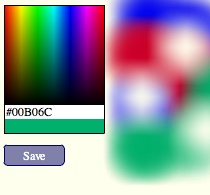
What’s Next?
One of the most surprising things to come to light after each major Flash upgrade is how small the engineering team manages to keep Flash Player. The bitmap manipulation and compositing features discussed in this chapter are by no means an exhaustive look at everything Flash Player can do with pixels. If you spent some time and effort on the project, you could make a fairly respectable graphics-editing application using only Flash (and, perhaps, a server technology like PHP for file management). The best examples of this that we can think of are the image editing applications available in the Aviary suite at http://www.aviary.com. Yet despite these capabilities, Flash Player still remains small and easy to install and update. Bravo, past and present Flash Professional and Flash Player engineers, and congratulations to the creative and programming team at Aviary!
Now it’s time to change direction and focus on the oft-overlooked workhorse of the Flash family: text. Text can be as fruitful a subject for experimentation and eye-candy as vectors and bitmaps, but it also serves a very important utilitarian purpose. Creating, styling, and parsing text are fundamental needs that you’ll frequently encounter.
In the next chapter, we’ll look at ways to work with text, including:
Creating text fields on the fly
Initializing basic text field appearance and behavioral attributes
Formatting text, including default formats for text fields, as well as changing formats across entire fields or partial text selections
Using HTML and Cascading Style Sheets (CSS) for limited HTML rendering and global styling
Embedding ActionScript triggers in HTML anchor tags
Parsing paragraph, line, and character data from text fields using points and indices