
Chapter 10 discussed some basic building techniques that apply to many different kinds of robots. This chapter explores some more specific techniques that may be useful in the Robot Game. First we discuss some simple but useful techniques, and then at the end of the chapter, we cover a few major techniques related to the design of FLL robots.
Due to the high accuracy required in some missions, you may need to position your robot very precisely in Base before sending it on a mission. You can do this in a few ways. One way is to use a sight that is similar to one used to aim a gun. Figure 11-1 shows a robot equipped with a basic sight.
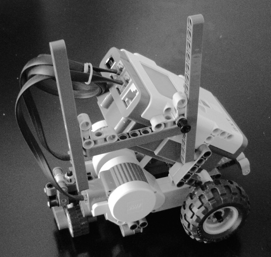
To use the sight to point the robot at an object beyond Base, hold your eye close to the left beam, and move the robot until both beams line up with that object. You can also position the robot by lining it up with graphics printed at Base, such as the borders. Sometimes the field mat even includes graphics specifically designed for this use. Figure 11-2 shows part of Base on the mat for the Power Puzzle season.
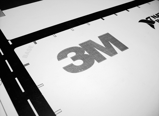
Notice the little line segments around the borders. Teams can align parts of the robot with these lines to help position it correctly. This allows the team to point the robot in a variety of specific directions. However, the features at Base may not provide the ideal reference points for orienting the robot exactly as desired. In that case, program the robot to turn to the correct position after using the features at Base to align it as close as possible.
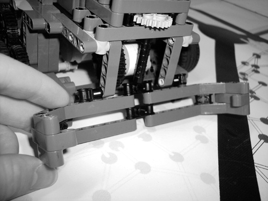
Although lining up the robot with graphics can be accurate, it can also be time consuming since it can take awhile to move the robot into just the right position. It may also take extra time and reduce accuracy if you need to turn the robot to a more precise direction after aligning it. Fix these problems by building aiming jigs. Aiming jigs are LEGO constructions, separate from the robot, that you can use to help aim the robot. Figure 11-3 shows an example.
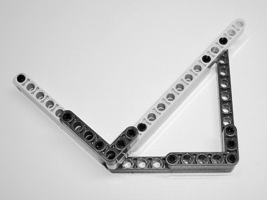
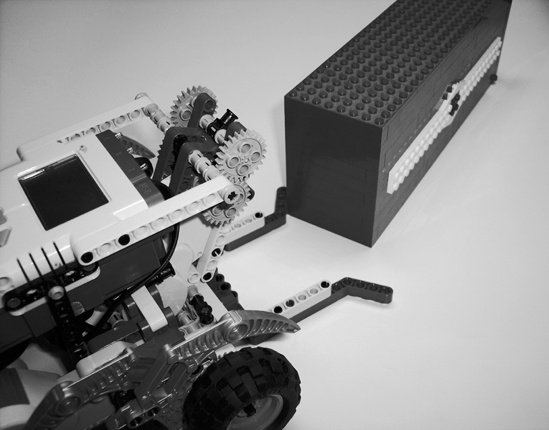
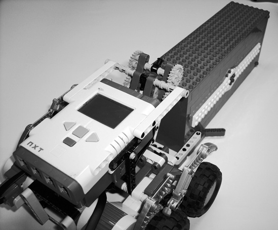
To aim the robot, place the aiming jig in a fixed position at Base, and then push the robot up against it to give it the desired alignment. Figure 11-4 shows an example of this process.
In the figure, the aiming jig is lined up against the back right corner of Base. The robot is pushed up against the other sides of the jig to arrange it at a specific position and angle. Notice how it ensures that every time you use the aiming jig, the robot always points at the same angle. Although it may take the drivers a while to position the aiming jig, they can do it while the robot is running a mission and then quickly push the robot into position against the jig.
The 4-inch border wall at Base could be considered a permanent aiming jig. You can push your robot up against it to make sure it’s straight and at the back of Base. However, be careful about doing this, as the mat may not always be pushed right up against the wall, which could cause your robot’s position on the mat (which is what counts) to vary slightly.
Although the field mat is ideally flat and completely smooth, real competition tables at tournaments often have bumps and/or aren’t completely level. It’s a good idea to prepare your robot to handle such imperfections.
Bumps in a table are actually quite common and can cause robots to go off course. The field mat may not be completely smoothed out, or objects, such as a screw that isn’t completely screwed into the table, may be under the mat. To minimize the effect of such bumps on your robot’s performance, it’s helpful if the robot has as little contact with the ground (besides the wheels) as possible. For example, a dozer that slides along the ground on the front of your robot could jolt the robot off course if it encounters something under the mat or goes over a hump. To avoid this, mount the dozer slightly off the ground, or connect it to a hinge so it simply rotates up out of the way when it encounters a bump. Figure 11-5 shows an example of such a dozer.
This dozer usually slides along the ground. However, if it encounters a bump in the mat, the hinge allows it to simply lift up and glide over it instead of forcing the whole robot up and possibly off course. Also be careful of pushing large objects across the mat, especially for long distances. This makes the robot susceptible to going off course should it encounter bumps and imperfections in the mat.
A slanted table can also cause your robot’s performance to vary. It may help if you give the robot a low center of gravity (by making it reasonably short). Using guide attachments, incorporating sensors, and making the robot frequently return to Base for realignment can also be helpful.
When testing your robot, consider simulating varying table conditions to see how well the robot handles them. For example, you could slip a kernel of rice or a coin under the mat to simulate bumps, or you could prop up one or more corners of the table with books or pieces of wood to simulate a slanted table. If the robot doesn’t adequately handle the simulation, experiment with different ways to fix the problem.
Even though MINDSTORMS materials usually make up the bulk of pieces used in FLL robots, you can use any LEGO pieces that you want! LEGO has made many interesting and unique pieces throughout the years, and you may want to take advantage of that. For example, one potentially useful piece is the weight brick (http://www.peeron.com/inv/parts/73090/); although it isn’t very big, it is quite heavy. Potential uses for this piece include balancing weight and holding something in place. Even if you don’t have many sets containing unique pieces, you may be able to find them at places such as eBay (http://www.ebay.com/) or BrickLink (http://www.bricklink.com/), which is an online market only for LEGO pieces and is especially useful for finding single pieces.
Some pieces that may be particularly useful are windup motors. You can use an unlimited number of these pieces, and they can act as temporary motors. For example, you could use a windup motor to make a “minirover” that the robot releases to speed across the table and hit a lever while the robot does something else.
No matter how hard you try to prevent it, accidents and damage can happen to a robot. It could be as simple as a team member tripping while carrying the robot to another table, causing the robot to explode into a hundred little pieces. You may want to thoroughly document the design so you can recreate the robot if something like this happens. This job would be the responsibility of the Building Backup Manager (discussed in Chapter 6).
One relatively easy way to create documentation is to take photos of your robot. It’s a good idea to take plenty of pictures, especially of the detailed components. You may even want to take the robot apart somewhat (making sure you can put it back together afterward!) to photograph in even greater detail. Keep the photos somewhere where they won’t get lost.
You can also document your robot by making a Computer Aided Design (CAD) drawing, a virtual 3-D copy of your robot on the computer, which you can “take apart” and view from any angle to see how you built the actual robot. Although this may sound complicated, it can actually be quite easy. LEGO makes some special software specifically for doing this called LEGO Digital Designer (LDD). Figure 11-6 shows an example of LDD.
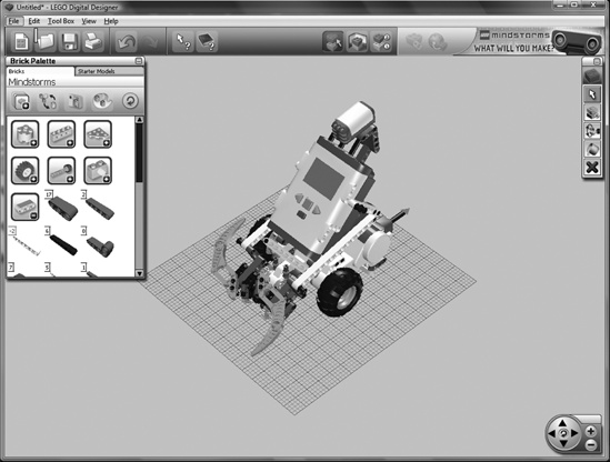
Download LDD from LEGO’s website at http://ldd.lego.com/. It’s easy to use and can even automatically create building instructions for models you make using it! Although LDD includes many kinds of LEGO bricks and pieces, it doesn’t include all of them. However, if your robot uses a piece that LDD doesn’t have, you can still document it by taking a photo of the piece and its place in the robot.
LDD has other limitations in areas such as piece placement and gear meshing. MLCAD, another LEGO CAD application, gets rid of many of these limitations, but it is also more advanced and takes longer to learn. Download and learn more about MLCAD at http://www.lm-software.com/mlcad/. You can download additional programs to make high-quality building instructions and renderings of models at http://www.ldraw.org/Article126.html.
MLCAD has models of almost all LEGO pieces and allows users to make very detailed and high-quality building instructions and design renderings. For example, in Chapter 10, the designs in Figure 10-13 and Figure 10-16 were made using this software. However, its advanced features probably aren’t that important for documenting your robot, so you may want to stick with LDD.
Now we get to some major techniques relating to the design of FLL robots. Since the Robot Game has several missions, your robot probably needs several kinds of mechanisms to accomplish them. It might be hard to build one robot with all of those mechanisms, especially with the three-motor limitation. However, the Robot Game is set up so you can add and remove mechanisms during a match! For example, your robot could use a grabber arm to accomplish one or more missions and then return to Base. The drivers could then switch the grabber arm for a long, spinning pole, which it can use to tackle the next mission. In this way, your robot can have a number of attachments and use one or two at a time.
Regularly having the robot return to Base also permits you to realign it, correcting any navigation errors that may have accumulated while attempting previous missions. This method does have a downside, though, in that it can take more time to modify the robot, properly position it, and run the next program. However, you’ll probably find that the advantages to this method far outweigh the disadvantages.
It can be helpful to build a robot that uses multiple removable attachments in two or three basic components: a chassis, the attachments, and possibly a bay. Let’s discuss each component, starting with the chassis.
Every robot built for the Robot Game needs mobility to accomplish missions. The main frame of a robot, which contains its mobility system (for example, its wheels), is called the chassis. You can consider the chassis the “base” of the robot, because it supports everything that attaches to the robot, such as auxiliary mechanisms. The basic chassis is a good component to build first, because the design of the bay and attachments will probably depend on how you build the chassis.
The rules for the Robot Game require that all robots fit inside a three-dimensional area called Base. For example, in the Power Puzzle season, Base was 17.75-by-13.25-by-16 inches. All robots must start completely in Base and leave autonomously before accomplishing any missions. For example, a robot would have to completely leave Base before hitting a lever on a mission model. When designing your chassis, consider making it significantly smaller than the size limit imposed by Base (in all dimensions) to allow for the addition of extra mechanisms, such as attachments, which will increase the robot’s size in one or more dimensions.
Before starting construction on the chassis, look at the field environment in the Robot Game to see how it might affect the design. Figure 11-7 shows the Ocean Odyssey season’s mat and mission models.
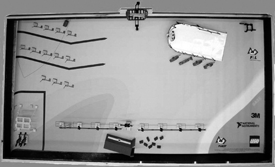
Apart from the mission models and small bumps and ripples in the mat, notice that the terrain is flat. This means that for this particular competition, you don’t need to make an all-terrain chassis; in other words, you probably do not need big wheels equipped with suspension that you might need for an outdoor course. Because the robot doesn’t have to go over any small obstacles, it doesn’t have to be very high off the ground. You also don’t need much traction or power for regular movements, since there are no steep inclines. Therefore, you might want to gear up the motors (as discussed in Chapter 10) to trade some of your power for extra speed.
The mission models might also affect the chassis design. For example, sometimes a robot needs to push or carry a model across the mat. Since these models are made out of LEGO pieces and usually aren’t very big, the robot shouldn’t need a lot of power to move them.
However, some missions may require the robot to move onto a model, which can require more power than regular movements. In the Ocean Odyssey challenge shown in Figure 11-7, the mission in the top-right corner required robots to move up a ramp made out of LEGO bricks to get to a submarine model. Having more power in the chassis can also enable the robot to force its way past a mission model if it nicks a corner or strays off course and bumps into it.
Mission models may also restrict the size of robots. For example, the ramp with the submarine restricted the robots’ width. If a robot was too wide, it wouldn’t fit on the ramp. Watch for tight spaces on the mat that might trap your robot; spend some time using a ruler to take measurements on the mat so your final robot design has the proper dimensions for accurate navigation.
Chapter 10 discusses using gears and different wheel sizes to adjust the speed and power of your chassis. Of course, the ideal speed and power for the Robot Game will vary from robot to robot, but we can make a few recommendations. Since the Robot Game doesn’t usually require much power, and since the NXT motors are more powerful, you may want to gear up the motors to gain extra speed, which can be quite important, considering the two-and-a-half-minute time limit.
Although you can construct the chassis in many ways, we recommend the following general procedure, which can help your team build the chassis in an effective and organized way.
Before beginning construction, brainstorm with your team, or at least the Building Team. Discuss ideas for possible designs, and then narrow down the suggested designs to a few of the best. Once you have a design short list, split into groups of two or three members (depending on the size of your team and the quantity of building pieces), and have each group build one of the ideas for a chassis. Don’t throw away any designs that show potential; the more designs, the better!
Once all groups finish their designs, have another meeting to test and modify them, and then choose the final design (on which you can improve as you test and build).
Sometimes a chassis might need a temporary boost of speed or power for one or two missions. For example, one mission in the Power Puzzle season involved two robots (on opposite sides of a table) racing to hit a lever first. In that mission, it was an advantage to have an extra-fast robot, but it might have been a disadvantage during other missions, due to its low power and less accurate movements. Therefore, it would be helpful to make the robot super-fast for just that one mission and slower for the others.
You can temporarily adjust the robot’s speed and power in a few ways. One easy way involves simply replacing the current wheels with wheels of a different size. Alternatively, you might stick larger wheels over the existing ones. As Chapter 10 discussed, larger wheels make the robot go faster with less power, while smaller wheels make it go slower with more power.
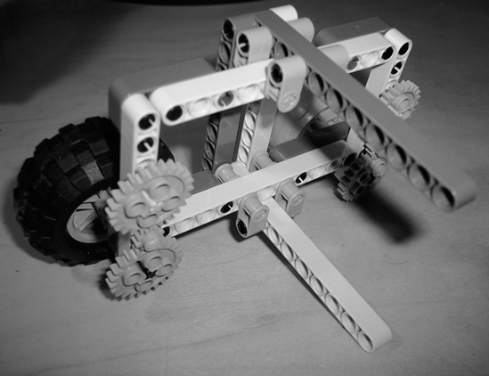
To allow for greater adjustments, consider using an adaptable chassis like the one shown in Figure 11-8. Although this method is more complicated than simply swapping out wheels, it offers many more options.
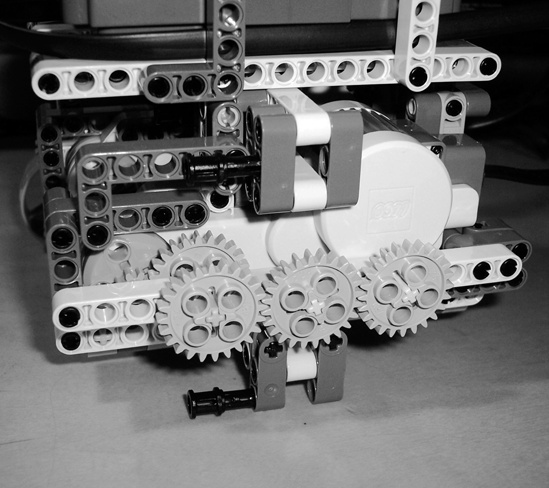
As you can see in the figure, one motor turns three gears on the outside of the chassis (another motor does the same thing for the other side). Above and below each set of three gears are slots for attachments. Figure 11-9 shows one such attachment.
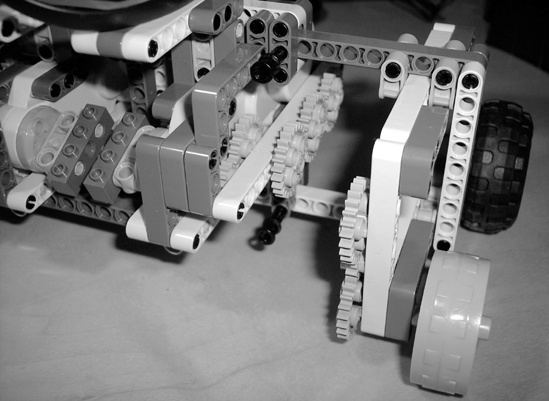
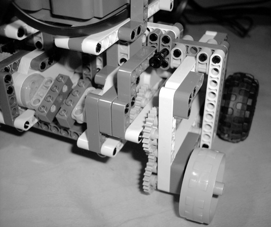
The attachment connects to the chassis using the two beams that extend outward (pegs hold them in). Once connected (see Figure 11-10), the three gears on the chassis mesh with the attachment’s gears, allowing the motors to drive the wheels.
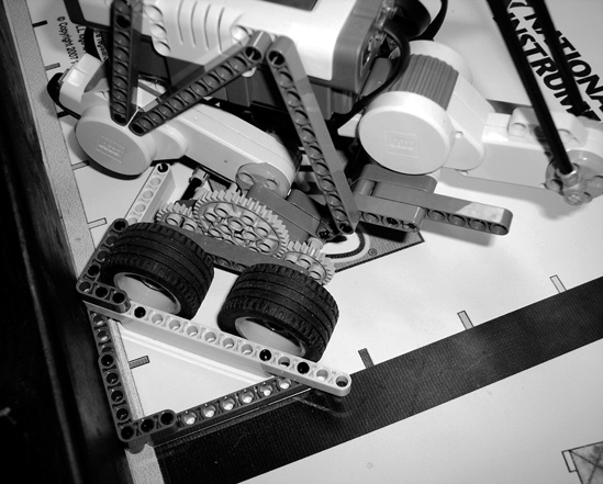
By attaching another of these attachments to the other side, we get a rover such as the one Figure 11-11 shows.
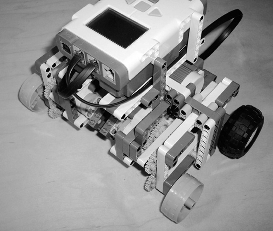
As you can see, an adaptable chassis like the one in our example allows you to completely change the robot’s mobility system simply by switching attachments! The robot could have treads during one mission, wheels during the next mission, and legs during the next; it can use whatever attachments you make for it. This can prove particularly helpful when you need to tackle different types of missions. For example, during a mission that requires the robot to get up on a platform above the ground, you could use an attachment with big wheels or treads. For other missions, you could transform it into less of an “all-terrain” chassis. If the robot needs a lot of speed for one mission, use a geared-up wheel attachment, and then use a slower, more powerful and accurate attachment for other missions.
When considering an adaptable chassis, remember that it comes with its own set of challenges. Adaptable chassis can be complicated and somewhat hard to make. Instead of simply driving wheels, the motors need to be able to drive any attachment. You also need a docking system that allows you to securely connect attachments to the chassis; if attachments aren’t held firmly, the robot’s accuracy and consistency could be affected. Ideally, your docking system should also enable you to quickly connect and remove attachments.
Due to the complexity of an adaptable chassis, its wheels might be farther apart than they would be otherwise. Notice how far apart the wheels are on the robot in Figure 11-6. This can decrease the robot’s sturdiness and make the wheels more apt to bend from the robot’s weight.
Switching attachments on an adaptable chassis can also take up valuable time during matches. When thinking about using different wheel attachments, consider whether the benefit of that attachment outweighs the extra time involved.
Although a chassis can move around, it usually can’t perform complicated actions, such as grabbing an object or removing objects from a mission model. To perform these kinds of actions, use attachments. Attachments are constructions you can connect to a robot to extend its capabilities by helping it do things like manipulating models, moving models around, and even navigating.
Many times, it’s possible to use a nonmotorized attachment to enable your robot to accomplish a mission. These attachments are simple tools the chassis can move to manipulate models. For example, a mission might require a robot to push an object off a high mission model. To solve this mission, the robot could use an attachment that simply extends above the chassis to hit the object.
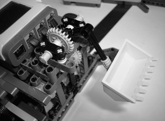
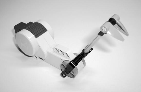
Sometimes, a nonmotorized attachment just won’t cut it. For example, you might need to drop an object into a specific place on a mission model. To accomplish this, you might use a motorized attachment similar to the one in Figure 11-12.
This attachment has a “bucket” that a motor can raise or lower, which enables the robot to carry a small object and drop it at the correct location.
Many of the attachments you use will probably be temporary and won’t stay on the robot for the whole match. However, some attachments will be of such general use that you will want them to be permanent features of the robot. Connect these attachments in such a way that they won’t interfere when connecting other attachments. For example, you might want to have a dozer on the front of the robot to push mission models around the mat. Simply connect this attachment to the front of the chassis, and keep it on for the entire match. Figure 11-13 shows an example of such an attachment.
Sometimes you can save time performing missions by making multipurpose attachments, which the robot uses to accomplish multiple missions. For example, you could make an attachment that has both a hook, to grab a model in one mission, and a stick, to push an object off a high platform in another mission. Even if the robot returns to Base for repositioning, you would not need to change attachments. Of course, the robot might not need to return to Base between missions, which would save even more time.
An attachment might not always work for multiple missions as it is, but could work if you slightly modify it between missions. Modifying an attachment instead of replacing it saves time as well as extra pieces. Figure 11-14 shows the “bucket” attachment in Figure 11-12 after modifying it to work on another mission.
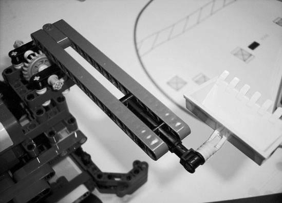
Instead of removing the first attachment and replacing it with the new one, simply remove the old bucket from the attachment and attach the new bucket construction. This can save time and won’t require two copies of the rest of the attachment.
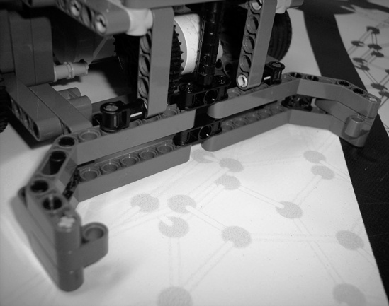
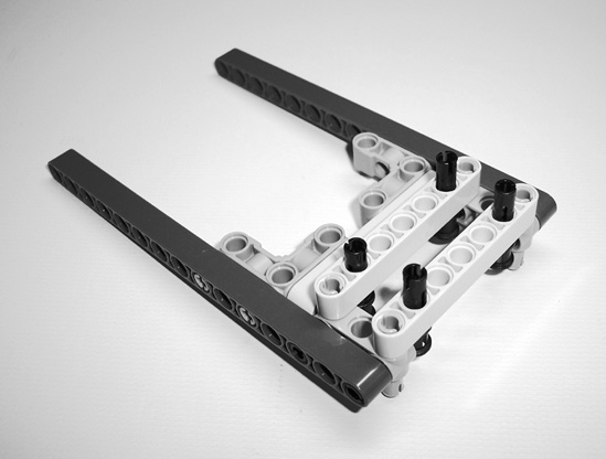
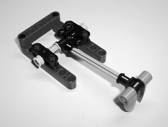
At the beginning of this section, we mentioned that attachments can help the robot navigate. How can they do that? Suppose that after traveling to a mission model, your robot needs to be at a specific place to work properly, but there may be some variability in exactly where the robot arrives at the model. This is where a guide attachment can help the robot realign itself. Figure 11-15 shows an example of a funnel attachment that accomplishes this very well.
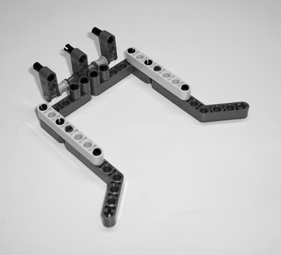
The two angled beams at the ends of the attachment help align the robot in the right position, similar to the way a real funnel guides liquid to the right place. Figure 11-16 shows how this works.
Even though the robot is off course initially, the funnel attachment forces it to curve to the left when it tries to move forward. This can be a great advantage because the robot can automatically realign itself without even knowing what it’s doing (as opposed to using sensors to try to correct its position).
Guide attachments can take many different sizes and shapes, and their designs will depend on each scenario. Basically, you want to make constructions that take advantage of stationary objects, such as a mission model or wall, to force the robot into the correct position. An object used to guide the robot could be as simple as a wall at the back of the robot that enables it to straighten itself out by backing into the table border. If you consistently have trouble getting the robot to the right place, look for opportunities to use guide attachments.
Attachments may sometimes extend significantly past the chassis, so it’s important to make sure they don’t cause the robot to exceed the size limitations. Just as with building the chassis, keep the size limitations in mind when building attachments. Pay special attention to the height limitation, since it is easy to exceed without using a tape measure. When there’s a significant advantage to using a larger attachment, you may be able to make an attachment that extends or “unfolds” after the robot leaves Base.
The design of your attachments depends largely on their respective missions. Therefore, you may want to build the attachment for each mission as you work on it. In other words, build the first attachment when you work on the first mission and the second attachment when you work on the second mission. After designing an attachment for one mission, look at later missions to see if you can use it as a multipurpose attachment, and look at previous missions to see if you can reuse an existing attachment (perhaps by modifying another attachment).
Attachments may also affect the order in which you run missions. For example, if you notice that the robot could use the same attachment for multiple missions, you may choose to run those missions in a row to avoid making unnecessary attachment switches.
It’s often helpful to have a single place on a robot where you connect each attachment. This makes attachments easier to build since you don’t have to figure out how to connect each one; you can simply use the bay. It also makes the robot more organized. A simple bay, as shown in Figure 11-17, is a platform that allows you to easily and securely connect attachments to the robot.
This bay would be built onto the rest of the robot, and attachments would snap on and off the four black pegs shown in the figure.
A simple bay like the one in Figure 11-17 usually isn’t sufficient, since it doesn’t have a motor with which to drive attachments. Since you can’t bring more than three motors to the competition table, you probably won’t be able to have one motor for each attachment, but you can share motors among attachments.
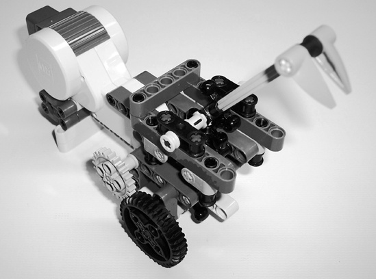
One way to share motors when switching attachments is to remove the motor from the first attachment, connect it to the second, and then connect the second attachment to the bay. However, this can eat up a lot of valuable time, so it’s usually much more efficient to have a motorized bay. Just like a simple bay, a motorized bay also has a motor that can drive connected attachments. Sometimes, the bay may consist of only a motor! In that case, you would simply connect attachments directly to the motor, such as the example that Figure 11-18 shows.
Depending on the size and complexity of the attachments, simply using a motor for a bay might not work so well. For example, having only one connection to the motor (the axle) might not be strong enough for larger attachments. Figure 11-19 shows an example of a more complex bay that can handle a wider variety of attachments.

When the motor spins, the black knob gear on top rotates. You can simply connect attachments that don’t need to be motorized to the four pegs and connect motorized attachments to the gear on the bay, as Figure 11-20 shows.
When the motor in the bay turns, it turns the gear on the attachment, which causes the hook to move up or down.
While you could build the bay after completing the chassis, it’s often easier to build the two at the same time. This method enables you to mold the chassis around the bay instead of trying to fit the bay into an existing chassis design.
Note
If you opt to build the bay after you build the chassis, lead a brainstorming session, and then have a few members build the bay. Since it usually doesn’t work well to have several members try to build the same thing, other members who want to help could provide feedback and suggestions on the builders’ work.
Although this chapter discusses several building techniques for the Robot Game, you can learn many others from resources such as the Internet. If you have specific questions, look for LEGO robotics-related email groups or forums. If you’re looking for general techniques, try tutorial websites or books. Also, browse through online robot galleries (such as NXTLog) to get ideas or inspiration. The appendix lists several helpful websites you may want to check out.