
![]()
Resistors
Sandwich, the line-following robot, uses many resistors on its circuit board (see Figure 9-1). These resistors are so vital that Sandwich could not operate without them. In this chapter, you’ll learn how to identify, purchase, and test resistors. In later chapters, you’ll put resistors into use in the same way that they’re used on Sandwich.
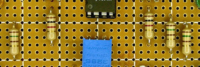
Figure 9-1. Five resistors on Sandwich’s circuit board
Limiting Power with Resistors
The main water supply hookup to your home is a fairly large pipe. But the pipe leading to your showerhead is a lot smaller.
Obviously, the smaller pipe saves some space, but it also acts to decrease the amount of water delivered to that location. You would not be pleased to begin your day with a shower blasting you with the full force of your water main! (Well, I don’t know you personally; perhaps you could use that much of a shower.)
Besides the displeasure of getting overwhelmed by a watery blast, a lot of water would get wasted. You don’t need that much water to effectively take a shower.
Resistors limit or divide up the flow of electricity. In doing so, they prevent waste and deliver the specifically requested amount of electricity to each part.
Obtaining a Resistor Variety Pack
Resistors are so useful and inexpensive that you’ll want to obtain a wide assortment of values. A good place to start is with a ½-watt, 5% tolerance, carbon-film variety pack (see Figure 9-2).

Figure 9-2. 100-piece assortment of ½-watt, 5% tolerance, carbon-film, through-hole resistors
Any of the resistor packs in Table 9-1 are perfectly adequate for a start. The Jameco #107879 includes a cabinet, which is nice.
Table 9-1. Resistor Assortments

Understanding Size and Tolerance
I recommend starting with ½-watt through-hole resistors because their larger physical size makes it easier to see the color code bands. If you want to use the smaller ¼-watt through-hole resistors instead, that’s fine. Until you become an expert, don’t buy surface-mount (SMT or SMD) resistors. Those are too small to experiment with (see Figure 9-3).

Figure 9-3. Top: 1-watt, ½-watt, ¼-watt, and ⅛ watt through-hole. Bottom: 1/10-watt surface-mount
5% tolerance means that a 100 Ω resistor could be as low as 95 Ω or as high as 105 Ω. That’s plenty accurate for homemade robots. You can spend a little more money and purchase 1% tolerance metal-film resistors, but your robot isn’t going to notice the difference. Many of the high-precision resistors have more than four color bands, which makes it more difficult for a beginner to decipher the value.
Cut It Out
Components often arrive connected together by tape bands (see Figure 9-4). This is because most components are manufactured in long reels so that they can be fed into robotic part-placement machines. A reseller purchases a full reel and then cuts off lengths according to your order.

Figure 9-4. Cutting resistors away from reel tape
You could try peeling off the tape, but it leaves a sticky residue on the ends of the wires. The residue can prevent a clean metal-to-metal connection when prototyping. The residue can also gum up sockets and holes.
Instead, use a wire cutter to cut both ends of the resistor from reel tape. Don’t use scissors because the cutting edges will become dulled and damaged.
If you absolutely need the full resistor wire length, you can pull the part from the tape and clean the ends of the resistor thoroughly. Resistors are hardy components; the cleaning won’t harm them at all.
Obtaining a Wire Cutter Tool
A wire cutter is an essential tool (see Figure 9-5). Not only can it cut components free from tape reels, but also it cuts raw wire, shortens tall component leads in solderless prototype boards, and trims excess material from circuit boards after soldering.

Figure 9-5. Flush wire cutter or nippy cutter
It may be worth buying a cutter from a local store rather than from a catalog (see Table 9-2), so that you can experience how a particular model feels in your hand.
Table 9-2. Wire Cutters
|
Supplier |
Part Number |
Price |
|---|---|---|
|
All Electronics |
FC-14 |
$4.50 |
|
Electronix Express |
0602MS01 |
$6.00 |
|
Jameco |
159274 |
$4.95 |
|
Jameco |
146712 |
$8.95 |
|
Micro-Mark |
80333 |
$14.25 |
|
SparkFun |
TOL-08794 |
$1.95 |
Resistance and Ohms
The unit associated with resistance is ohms. This is abbreviated with the symbol Ω. So, 100 ohms is the same as 100 Ω. There isn’t any difference.
It doesn’t matter if you understand or have a feel for ohms yet. Recall that resistance is like the smaller pipe sizes and tiny holes in your showerhead. A larger ohm number represents larger resistance, which is sort of like a narrower pipe.
Most electronic parts can’t take the full force of the battery. They need something to reduce the flow; that’s what resistors do.
Measuring Resistance
- If your meter isn’t already on the 200 range (or thereabouts) for ohms, switch the dial now.
- As always, connect the black lead to the COM terminal of the multimeter.
- Connect the red lead to terminal marked Ω or ohm or whatever the specific instructions are for measuring resistance on your particular meter.
- Turn on the meter.
It would be helpful to use alligator-clips or hook adaptors (if you have them) for your meter test probe tips. It’s somewhat difficult to touch each end of a resistor with both probe tips at the same time without the resistor rolling away.
- Find a 100 Ω resistor. The color bands are brown, black, brown, gold. There’s no such resistor as gold, brown, black, brown (backwards). If you think you’ve found one, you’re reading in the opposite direction.
In a prior chapter, the color-code table indicates that brown is 1, black is 0, brown is × 10, and gold is 5% tolerance. That is 100 ± 5 Ω.
 Note The symbol ± means plus or minus. In this example, 100 plus 5 is 105 and 100 minus 5 is 95. So, the value of the resistor could be anything from 95 to 105.
 - Touch or connect the black probe tip to one end wire of the resistor (see Figure 9-6). It doesn’t matter which ends you choose.

Figure 9-6. Hook test probe adaptors holding a 100 Ω resistor
- Touch or connect the red probe tip to the other end wire of the resistor.
Interpreting the Resistance Displayed on the Meter
If you’re freakishly lucky, the meter is displaying 100 Ω. More likely, the meter is showing a number slightly above or below 100. That’s perfectly normal. (I can’t tell you how many resistors I went through to get that near to 100 Ω for the picture in Figure 9-7.)

Figure 9-7. Meter displaying resistance of approximately 100 Ω
If your meter is displaying 0L or some very large number, double-check the setting you’ve chosen on the dial. Is it ohm? Is the range more than 100? Wiggle the test probe connections to make sure everything is firmly connected. Check the colors of the resistor again; perhaps your third band isn’t brown (times 10)?
A resistor that’s undergone aging, temperature extremes, shock, or other abuse may be damaged out of the expected value. However, it is really unlikely that a fresh, 5% tolerance, 100 Ω resistor would be beyond the appropriate 95 Ω to 105 Ω range. You can always try a few other resistors to be sure.
Experiencing Resistance Ranges
- Find a 470 Ω resistor. The color bands are yellow, purple, brown, gold.
- If you have a manual-ranging multimeter, choose an ohm range below 470 on your meter. We’re goofing around for a minute here.
- Hook up the 470 Ω resistor as you did the 100 Ω resistor (refer back to Figure 9-6).
Unlike an improper voltage range, choosing too low of a maximum range on the ohm-portion of the dial does not harm your multimeter at all. However, the manual-ranging meter will be unable to display a measurement of the resistance. On my meter, 0L is displayed instead of the proper value (see Figure 9-8).

Figure 9-8. The resistor value is above the selected range on the multimeter
This is one of the annoying aspects of a manual-ranging meter. In order to determine the resistance of something, you either have to make an educated guess (by looking it up in a color-code table) or you have to flip through the ohm ranges on the dial until you get a reading.
Because of the need to constantly try different ranges on the dial of a manual-ranging meter, it’s more difficult to sort a box of resistors. That same task is a breeze on an autoranging meter.
If you have an autoranging multimeter or have now chosen the correct range on your manual meter, you may find that your meter displays the value of the 470 Ω resistor as 0.470 kΩ more or less (see Figure 9-9). This value is still correct. The k stands for 1000. If you multiply 0.47 by 1000, you’ll get 470.

Figure 9-9. Non-friendly display of an in-range resistor value on a multimeter
As multimeters have gotten smarter, they do a better job of displaying numbers in user-friendly ranges. If your meter doesn’t present all numbers nicely, be prepared to think twice when a decimal point appears on the meter.
Looking Up Resistor Values Online
The benefits of measuring a resistor using a multimeter are that you don’t need to decipher the color bands and you know for sure the actual value of the resistor. But, the process is time-consuming.
Robot Room features a visual resistor calculator (see Figure 9-10) where you can either select the colors or enter the resistance value. Go to: http://www.robotroom.com/Calculators/Resistor/Resistor-Color-Code-Calculator.aspx

Figure 9-10. Online resistance calculator
Labeling and Storing
Measure and sort all of the resistors in your variety pack. If the resistors are attached by reel tape, keep them together and write the value on the tape (see Figure 9-11).

Figure 9-11. Resistors still connected to reel tape with hand-written value at bottom
I like to store my resistors in groups based on their third (multiplier) color band. That is, I organize resistors together that have a value between 0 and 99 (black), 100 and 999 (brown), 1 k and 9.9 k (red),
10 k and 99 k (orange), 100 k and 999 k (yellow), and 1 M and up (green, blue). Checking for a single color band makes them easy to sort and to find values that are out of place.
Obtaining Storage Cases
Buy a bunch of plastic storage cases with movable compartment separators (see Figure 9-12). It’s easier to stack cases if they’re all the same size, and, as a robot builder, you’re going to have lots and lots of different parts. You’ll want to be able customize the size of the individual compartments within the cases to fit the size of your parts.

Figure 9-12. Components sorted in a storage case or organizer
You can find inexpensive storage cases at hardware stores and variety retailers, or tackle boxes at sporting-goods stores. Most parts (resistors, capacitors, switches, wire, screws, potentiometers, connectors, sockets, motors, magnets, and so on) don’t need to be stored in any special kind of materials or plastic.
Choose a sturdy case that closes firmly and whose inner walls reach from the bottom to the top of the case. If the container should fall, you don’t want your neatly sorted parts to jump over short compartment walls and become disorganized.
Resisting the Temptation to Skip Ahead
Now you’ve got a broad collection of resistor values at your disposal. You’ll never build a robot without them. However, before you can start using them in a circuit, you’ll need to learn about one more part . . . LEDs.