
![]()
Power On!
Nearly all robots need a power indicator light. It’s a very simple circuit to build.
In this chapter, you’re going to make a power indicator using the parts and tools you’ve read about in the previous chapters. You’ll learn a little about the role of each component and how to use the multimeter to test that the circuit is working as designed.
A circuit description generally includes a parts list, schematic, and wiring diagram, as well as photographs and step-by-step building instructions. As you gain experience, you’ll discover that all circuits reuse common techniques and patterns, so their accompanying documentation mostly focuses on the core concepts or tricky portions.
Introducing the Parts List
A parts list is a brief description of each of the components that are in a circuit. Sometimes tools will be mentioned in a parts list, but usually not. Small circuits typically don’t include parts lists, as the illustration or diagram of the circuit provides enough information to figure out the required inventory.
Here’s the parts list for the power indicator circuit:
- Multimeter for testing
- 9 V battery, preferably rechargeable
- Three alligator clip jumper leads, preferably red, green, and black
- 1 kΩ resistor (brown, black, red, and gold color-code bands)
- Red LED
Testing the Parts Before Assembly
Before building, be sure to test all of your parts with a multimeter. This isn’t vital when you’re connecting stuff together temporarily with alligator clips. However, it’s sensible to test each part if you’re going to permanently solder them, especially if any expensive parts are involved.
From the prior chapters, you know how to use your multimeter to test for the following requirements:
- The battery’s voltage should be between 7 V and 10 V. A reading of 9 V is optimal.
- The alligator jumpers should have less than 1 Ω resistance (good continuity).
- The 1 kΩ resistor should be between 950 Ω and 1050 Ω.
- The red LED should have a voltage drop between 1.4 V and 2.0 V.
Reading a Schematic
A schematic illustrates the logical connections between all of the parts (see Figure 11-1). Different types of parts have different symbols. The symbols don’t look much like the real life object, but after you’ve seen a few schematics, you’ll begin recognizing the symbols.
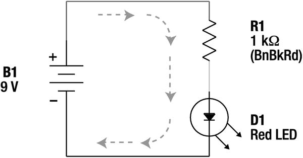
Figure 11-1. Power indicator circuit schematic
Each part is labeled with a letter and number. The letter relates to the type of part, like “R” for resistor. This is a nice hint if you don’t recognize the schematic symbol.
Along with the letter, there’s a number that ensures that each part is labeled uniquely. If two resistors appear in the schematic, they would be labeled R1 and R2. The number doesn’t necessarily suggest anything about the location or value of the part; it simply gives it a distinctive name.
A bit of significant information about the part is usually displayed in the schematic along with the part label. Referring to the schematic in Figure 11-1:
- B1 – 9 V battery. Notice the location of the positive (+) and negative (-) indicators. The symbol for a battery is two or more horizontal lines of different widths.
- R1 –1 kΩ resistor. “(BnBkRd)” is my shorthand for indicating that the resistor’s color-code bands are brown, black, and red. The last band, tolerance, is usually omitted as most resistors are gold (5%) or better nowadays. The symbol for a resistor is a sharp, squiggly line.
- D1 – Red LED. I used the letter “D” because an LED is a diode. It would have been perfectly acceptable to use “LED1.” In fact, “LED1” is preferable in circuits that contain other types of diodes. Notice the symbol inside the circle is the arrow crashing into a wall, just like on the multimeter dial. The two arrows coming out of the circle represent light emissions.
- Center arrows – (five arrows in the middle) Sometimes arrows are drawn to show the flow of electricity though a circuit. In this conventional depiction, electricity comes out of the positive terminal of the battery, through the resistor, through the LED, and into the other end of the battery.
Building the Power Indicator Circuit
You’re now going to build the power indicator circuit by connecting the parts together with alligator clips (see Figure 11-2).

Figure 11-2. Photograph of the assembled power indicator circuit
- Connect one red alligator clip to the positive terminal of the 9 V battery.
- Connect the other red alligator clip (the other end of the same red jumper) to one lead (wire) of the resistor. It doesn’t matter which end of the resistor is connected.
- Connect one green alligator clip to the other end of the resistor.
- Connect the other green alligator clip to the anode lead of the red LED. See the earlier chapter if you don’t remember how to locate the anode lead.
- Connect one black alligator clip to the cathode lead of the red LED.
STOP! The last connection is going to be to the other end of the battery. But, you should always check your circuit before making the final connection to the battery. With only one connection to the battery so far, no electricity is flowing.
For a moment, pretend you’re a lazy drop of electricity. The battery is a pump shoving you (electricity) out of the battery and into the wire pipe. You don’t like being outside of the battery. Your mission: Get back to the battery as quickly and easily (you’re lazy) as possible. If you can find any shortcuts, take them. Jumping through the air is not easy, so that’s not a shortcut.
Are any metal pieces touching any other metal pieces by accident? Those are great shortcuts.
Make sure that the electricity has no choice but to go out the battery, through the red jumper, through the resistor, through the green jumper, through the LED, and then into the other end of the battery. This is the path you want the electricity to take in its quest to return to the battery.
Ready?
- Connect the remaining black clip to the negative terminal of the 9 V battery.
Do You See The Light?
Hopefully you’re patting yourself on the back for a job well done. You’ve got a beautiful red light.
If the red LED isn’t lit, check all of your connections. Alligator clips tend to slip off.
If the red LED still isn’t lit, perhaps it’s in backwards. No harm done. Disconnect both ends of the LED, flip it around, and reconnect both ends.
Experimenting with the Power Indicator Circuit
After admiring your red LED for a while, here are some things to try:
- Disconnect the red LED and put a different color or size in its place.
- Reverse the resistor connections. It won’t make any difference; the resistance won’t change. Resistors are non-polarized. That is, resistors don’t care which end is connected to the negative or the positive. This is a fairly boring experiment since nothing happens differently when the resistor is flipped, but that alone is worth noting.
- Reverse the LED connections. It won’t light in the wrong direction. LEDs are polarized. That is, they do care which end is connected to the negative and the positive.
- Disconnect any one of the alligator clips. The LED turns off. It doesn’t matter where you disconnect a circuit; if the entire branch or loop isn’t connected to both ends of the battery, it stops working. (Because the pipe cuts off before reaching the other end of the battery, there isn’t anywhere for the electrical drops to go. With nowhere to go, there isn’t any room for more drops to get squeezed out. It’s a bad traffic jam on a dead-end street.)
Understanding the Roles of Each Component
Each part of the power indicator circuit provides a vital function.
The battery, B1, is the pump. It takes electrons (electricity drops) and sends them around and around the loop.
The alligator clips and wire leads are the pipes. They deliver the electrons to the desired parts.
The resistor, R1, protects the “delicate” LED from the full force of the battery. Recall that resistors are like narrower pipes or skinny holes that only let a desired maximum amount of electricity through.
The resistor’s restriction of flow also prevents waste. We only care that the LED lights up, we don’t want to use any more battery power than that.
The red LED, D1, is the purpose of the circuit. The battery, wires, and resistor are only there to provide for the LED’s needs.
Measuring the Power Indicator Circuit
Within a circuit, there are two useful measurements that you can make: voltage (pressure) and current (flow).
Measuring In-Circuit Voltage
Testing voltages throughout a circuit is the most common test you’ll perform. This tells you whether each part is receiving the desired range of “pressure.” Too little voltage and the part won’t operate; too much voltage and the part will break.
- Set up your multimeter as you would to measure battery voltage (see Figure 11-3). Use a hook or alligator clip adapter on the black (COM) test probe. However, the red test probe should be a bare metal tip since you’re going to move it around a lot.

Figure 11-3. Multimeter setup for measuring voltage at various locations in a circuit
- Turn on your LED circuit. The measurements are going to be made with the power on.
- With the black alligator clip still attached, connect the multimeter’s black test probe hook to the negative terminal of the 9 V battery (see Figure 11-4). The black test probe will stay there as you touch the red test probe tip to various other locations on the circuit.

Figure 11-4. Black probe hooked onto negative battery terminal. Red probe can be moved freely
- When you touch the red test probe tip to the positive terminal of the battery, the multimeter should indicate the battery’s voltage as expected. My battery is 9.15 V.
- Touch the red test probe tip to the clip at the other end of the red alligator jumper. You shouldn’t see any change in voltage. Remember, the jumper wire is just a pipe; it shouldn’t use up any voltage.
- Touch the red test probe tip to the top resistor lead. You still shouldn’t see any change in voltage. The resistor lead is also a pipe.
- Touch the red test probe tip to the lower lead of the resistor (see Figure 11-5). Finally some action! The voltage should drop significantly. My circuit is 1.8 V at this point.

Figure 11-5. Red probe detecting the voltage at the point after the resistor
What happened? The resistor did its job. It reduced the voltage to an amount acceptable to the LED coming up. (That’s not exactly a technically accurate explanation, but good enough for now.)
- Touch the red test probe tip to each of the green alligator clips and then to the anode of the red LED. The voltage should still be 1.8 V (or whatever you saw earlier). The green jumper and anode wire are pipes. They aren’t using up voltage.
- Touch the red test probe tip to the cathode of the red LED. The voltage should drop to zero at this point. The red LED used up all of the remaining voltage.
- Touch the red test probe tip to the black alligator clips. Zero voltage. Touch the red test probe tip to the negative terminal of the battery (same as the black test probe hook). Zero voltage. No matter what parts you install in a circuit, by the time the electricity reaches the other end of the battery, the voltage is always zero.
Measuring Voltage “At” a Point
The test method you’ve just been using answers the question, “What’s the voltage at such-and-such a point?” To check the voltage at a particular point, always connect the multimeter’s black test probe to the negative terminal of the battery and touch the red test probe to the point in question.
As you make your way down the circuit, the voltage decreases as each major part uses up some voltage.
Measuring Voltage “Drop” or Voltage “Across” a Part
Often you’ll be interested in how much voltage a particular part uses up by itself. One way of determining this is to perform a little math.
Here’s what I calculated for my circuit:
The voltage before the resistor is 9.15 V. The voltage after the resistor is 1.8 V. So, the resistor uses 7.35 V.
The voltage before the LED is 1.8 V. The voltage after the LED is 0 V. So, the LED uses 1.8 V.
You don’t need to calculate these numbers. You can test the voltage usage of an individual part with a multimeter. The meter dial stays the same from the last voltage measurement, except now the red test probe goes above the resistor and the black test probe goes below the resistor (see Figure 11-6). The meter should display 7.35 V (or whatever you calculated for your circuit).

Figure 11-6. Red and black test probes detecting the voltage dropped only by the resistor
![]() Caution Don’t test the resistor’s resistance with the multimeter’s Ω mode while the resistor is in the circuit!! Only use voltage mode in a circuit, not Ω mode. Otherwise, you might damage your meter.
Caution Don’t test the resistor’s resistance with the multimeter’s Ω mode while the resistor is in the circuit!! Only use voltage mode in a circuit, not Ω mode. Otherwise, you might damage your meter.
In Ω mode, the multimeter actually supplies its own voltage to the test resistor and measures how much of the voltage is consumed by the test resistor in comparison to a known-value resistor inside the multimeter. As such, the multimeter is not expecting voltage to already exist across the test resistor. If a high-enough voltage already exists, the external electrical pressure can break through the unsuspecting circuit inside the meter.
On the other hand, a multimeter in voltage mode expects external voltage to be in the circuit, because that’s exactly what the multimeter is supposed to be measuring. So, as long as you dial a reasonably high-enough voltage range on the multimeter dial, the multimeter’s electronics are designed to expect and thus withstand external voltage.
Test the voltage used by the LED by placing the red test probe above the LED and the black test probe below the LED (see Figure 11-7). The meter should display 1.8 V (or whatever you calculated for your circuit).

Figure 11-7. Red and black probe detecting the voltage dropped by the LED
In an earlier chapter, you tested the LED using the diode mode of the multimeter. The amount of voltage being used up by the LED in a circuit will usually be a little higher than the multimeter diode mode indicated.
![]() Caution Don’t test the LED with the multimeter’s diode mode while the LED is in the circuit!! Only use voltage mode in a circuit, not diode mode. Otherwise, you might damage your meter.
Caution Don’t test the LED with the multimeter’s diode mode while the LED is in the circuit!! Only use voltage mode in a circuit, not diode mode. Otherwise, you might damage your meter.
In diode mode, the multimeter actually supplies its own voltage to the test diode, just like it supplies its own voltage to test resistors in Ω mode. External voltage in the diode may be high enough to melt unprepared circuits inside the meter.
Summarizing Circuit Voltage
The wires (alligator jumpers and component leads) didn’t use any voltage. The LED used about the amount of voltage the meter’s diode mode said it would. The resistor used up the remaining voltage.
Depending on where you place the test probes, the multimeter can measure the voltage at a particular point or the voltage used across a single part.
Measuring Current Flow
The second most common test you’ll perform on a circuit is current flow. Voltage measures how much force each drop has; current is a count of how many drops are going through the circuit. Current is a vital measurement for determining how long your batteries are going to last.
- Disconnect the multimeter test probes if they are presently connected to the circuit.
- As always, the black test lead is connected to the COM terminal on the multimeter.
- But, the red test lead now needs to be unplugged from the V terminal and connected to the A or mA terminal on the multimeter (see Figure 11-8). Check your meter manual for exact instructions.

Figure 11-8. Multimeter setup for mA current flow
- For this measurement, both the red and black probes should have hook adaptors on the ends.
- Rotate the meter dial to the mA, A, or amp function. If you have a manual ranging meter, you’ll want to choose some number over 20 mA (milli). If you prefer, you can start at a higher range and work your way down.
Previously, when measuring voltage, the meter test probes always connected on top of an existing part. You didn’t need to disconnect anything in the circuit to make the measurement. However, to measure current flow, the meter needs to have all electrical drops pass through the meter to be counted. Think of it like a subway turnstile. Nobody is allowed to continue through the circuit until they pass through the meter.
- Hook up your power indicator circuit and make sure the LED is lit.
- Now, disconnect the red alligator clip from the positive terminal of the battery and connect it to the black test probe hook (see Figure 11-9).

Figure 11-9. Power indicator circuit connection for current-flow measuring
- Connect the red test probe hook to the positive terminal of the battery.
With this setup, all of the electricity that leaves the battery is going into the meter’s red probe, through the meter for counting, out the meter’s black probe, and into the red alligator clip. With this arrangement, the meter is guaranteed to count every drop of current pushed out by the battery and used by the circuit.
If all goes well, the red LED should be lit and the meter should be displaying between 5 mA and 10 mA. My circuit measured 7.2 mA (see Figure 11-10).

Figure 11-10. Multimeter displaying 7.2 mA of current flowing through circuit
If the LED doesn’t light, check all of the connections and the dial settings. If the value displayed on the meter is negative (like -7.2 mA) then you’ve got the black and red test probes reversed.
Calculating Battery Life
Assuming you have a fresh 9 V battery in your circuit, you can now determine how long it will last. Usually the fresh battery capacity is published on the package or on the manufacturer’s web site. If you don’t know the official capacity rating of your 9 V battery, you can assume 595 mAh for alkaline and 150 mAh for rechargeable.
Take the mAh (milliamp hour) battery capacity and divide it by the mA (milliamp) current usage of your circuit. This tells you how many hours the battery can power your circuit.
For example: I have a 150 mAh rechargeable battery and my power indicator circuit is using 7.2 mA.
150 mAh / 7.2 mA = 20.8 h
That’s almost 21 hours.
Extending Battery Life
If you can reduce the current flow, you can extend the battery life. Recall that resistors not only protect the other parts from the force of the battery, but that resistors also prevent wasted power.
Instead of the 1 kΩ resistor, try substituting a 2.2 kΩ resistor (red, red, red, gold color bands). That’s slightly more than double the resistance. It’s twice as good as resisting flow. Go ahead and try that now.
The multimeter should reflect the decrease in current flow due to the 2.2 kΩ resistor. My circuit went from 7.2 mA down to 3.4 mA. That means the battery life is now 44 hours:
150 mAh / 3.4 mA = 44 h
However, the LED isn’t as bright as it was.
Try some other resistor values (see Figure 11-11). You can pick values as large as you want, but don’t go below 470 Ω. Watch the meter and observe the brightness of the LED.

Figure 11-11. Resistor values for experimenting: from 10,000 Ω down to 470 Ω
As the Ω value increases, the battery life increases but the LED dims (see Table 11-1). As the Ω value decreases, the battery life decreases but the LED brightens.
Table 11-1. Resistance Versus Battery Life and Brightness

It is important to note that the LED’s brightness depends on the current flowing through it, not the voltage. Many electronic parts work this way. They are said to be “current driven.”
Selecting Resistors
When I first started experimenting with electronics, I couldn’t figure out how people chose the values for resistors. Somehow I thought there would be one absolutely correct value for a specific use.
Within a particular range, resistor value selection is a matter of taste. It depends on the designer’s perception of performance. If the LED is bright enough at 2,200 Ω, that will save on battery life. If battery life isn’t an issue but brightness is, perhaps 1,000 Ω is a better choice. Resistor values are negotiable.
How bright can the LED get? According to the manufacturer’s datasheets, the maximum rated current for my LED is 30 mA.
You could move the multimeter test probes to immediately before the LED to test the amount of current going through the LED. You’d reconnect the red alligator clip to the positive terminal of the battery. Then you’d disconnect the green alligator clip from the LED anode and connect the meter probes in between (see Figure 11-12).

Figure 11-12. Counting current between the green clip and the LED
But, since there isn’t any return path to the battery except for the one that goes through the LED, the count of electrons coming out of the battery is the same count as those going through the LED and returning into the other end of the battery. All the current that leaves the battery must pass through the LED. So, there’s no reason to move the multimeter probes to determine the amount of current flowing through the LED.
Calculating Current
Here’s a simple formula that allows you to predict how much current a circuit will use before you build the circuit.
(V / Ω) × 1000 = mA
Let’s see if the formula matches our test results. For my circuit, the voltage at the resistor is actually 9.15 V and the resistor’s resistance is actually 1020 Ω.
(9.15 V / 1020 Ω) × 1000 = 8.97 mA
Oh no! Something’s wrong. 8.97 mA is predicted but only 7.2 mA was measured.
Ah ha! The resistor doesn’t use all 9.15 V; the LED uses some. The resistor only uses 7.35 V.
(7.35 V / 1020 Ω) × 1000 = 7.2 mA
Perfect.
Minimum Resistor for LED Formula
Here’s a formula that allows you to determine the lowest value resistor you can use to protect an LED. You need to test your battery’s voltage and test the LED in the multimeter’s diode mode. You need to look up the LED’s maximum forward current rating on the manufacturer’s datasheet.
(battery voltage - LED voltage) / (maximum LED current in mA / 1000) = minimum resistor
For the power indicator circuit:
(9.15 V - 1.8 V) / (30 mA / 1000) = 245 Ω
The calculation reveals a 245 Ω minimum, but earlier I warned you not to go below 470 Ω. Well, that provided a bit of safety in case your battery had a little more voltage or your LED used a little less voltage.
Don’t Measure Voltage with Probe in Current Terminal
To test current, you had to pull the red test lead from the V terminal on the multimeter. You put the red test lead into the mA, A, or amp terminal. This formed a pipe in the multimeter to let the electricity flow through and get counted.
Let’s say you now decide to test the voltage of the resistor but you forget to put the red test lead back into the V terminal. You put the red and black test probes above and below the resistor. Poof! Suddenly your light emitting diode becomes a smoke emitting diode.
![]() Note Just kidding. The LED dies without drama.
Note Just kidding. The LED dies without drama.
What happened? Because the multimeter has become a pipe to test for current, the electricity can now get around the resistor (see Figure 11-13). It’s like the resistor isn’t in the circuit anymore. The LED takes the full force of the battery, destroying it.

Figure 11-13. Electricity accidentally getting around the resistor through multimeter amp mode
Don’t laugh. You’re going to do it one day.
The point is, be sure to switch your red test lead back to the multimeter’s V terminal before you test for voltage. Or, an even safer practice is to get in the habit of always putting the meter’s red test lead back into the V socket and turning the dial to voltage mode as soon as you’re done measuring current.
Circuit Summary
Important things described in this chapter:
- A schematic is a symbolic illustration of the parts in a circuit.
- Each part in a schematic is labeled with a letter and number so that it can be referred to without confusing it with any other part in that particular schematic.
- You can test voltage at any point by connecting the black test probe to the negative end of the battery and touching the red test probe to the point to be measured.
- You can test voltage used by (dropped across) a particular part by connecting the red test probe immediately before and the black test probe immediately after the part to be measured.
- You can test the current used by an entire circuit by changing the multimeter mode, switching the red test lead terminal, and connecting the test probes in line with the positive terminal of the battery.
- Battery life is directly proportional to the amount of current a circuit uses.
- The amount of current that passes through it controls the brightness of an LED.
- You can adjust current by changing resistor values.
- Too much current can destroy an LED, so always use a resistor to protect it.
Alligator clips work satisfactorily for short, simple circuits that contain only a few parts. However, sometimes clips slip off and sometimes the exposed pieces of metal accidentally touch each other. Sometimes the circuit even becomes a giant tangled ball.
There is a much better way to quickly create test circuits. Read on!