![]()
Appendix B
This appendix covers printing Sandwich robot parts. A 3D printer is so essential to robotics that it will become as commonplace as the multimeter. The appendix begins with laying out a Lego cross-axle coupler in a CAD (computer-aided design) program. From there, several failures in creating a rubberized wheel are followed by a successful hybrid. Finally, the robot’s body connects everything together in a complete custom package.
Most robots are unique creations. Often, you either need to machine custom parts (requiring a shop and experience) or you need to compromise your imagination by repurposing mass-produced objects (such as sandwich containers). But with a 3D printer (see Figure B-1), you can quickly design and output exactly the part you need.
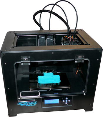
Figure B-1. A consumer 3D printer about the size and cost of a small-business laser printer
Custom-designed robot bodies can be smaller and lighter. Rather than using screws to fasten together multiple brackets inside a fixed-size project box, you can create a single body of the optimal size that incorporates all of the attachment locations. For example, the separate battery holder and the circuit board standoff hardware are no longer needed in the 3D printed Sandwich robot (see Figure B-2).

Figure B-2. All of these screws, nuts, washers, and standoffs are eliminated by incorporating those elements in the printed robot platform
Robot builders sometimes drill holes in the wrong locations or don’t leave enough room for connectors and wires. Occasionally, a robot body needs to be discarded entirely because the motor location is poor or a critical part doesn’t fit. With 3D printing, the design can be tweaked on the computer and reprinted. For example, I needed to flip the offset-shaft motor hole upside down so short wheels would reach the ground (see Figure B-3). An added advantage of this change was that the top curved portion was no longer needed, and was removed to reduce weight.

Figure B-3. A large motor hole is easily repositioned with 3D design and printing
Leaping Not Very Far
At first, 3D technology may seem intimidating, but it has become so simple that even a beginner can pick up enough knowledge in a weekend to produce competent prints.
What if you don’t have the money to buy a 3D printer, don’t have the knowledge to choose a printer, or aren’t sure you’re ready to make the investment? Fortunately, many 3D printing services exist where you upload a design file and they mail you the printed object. Moreover, these services often have industrial equipment that can produce higher-quality prints and can print in materials that consumer printers don’t support, such as metal or ceramic.
Many local libraries and hacker spaces also have publically accessible 3D printers. This allows people to obtain parts without shipping delays and to learn from each other.
Rapidly Improving
There were many different technologies in the early days of 2D printers: typewriter-based, dot matrix, thermal ribbon, wax, ink-jet, and finally laser. Printers competed on speed, quality, colors, price, and resolution. Guess what? Those same criteria apply to 3D printers, with a couple of additions: output material choices and support of complex structures.
I could write an entire book on the subject of three dimensional printing. But, many other authors have already done so, and the 3D printers are evolving so quickly that the written material quickly goes out of date. Therefore, this chapter will instead concentrate on applying consumer-level 3D printing technology specifically to the Sandwich robot in this book.
The most complicated piece of Sandwich is the part that connects the motor shaft to the Lego wheel. Over the years, I’ve tried many ways to perfect this coupler and decrease the time and equipment necessary (see Figure B-4). Now, with a 3D printer, the coupler can be printed in 20 minutes at home without filing, cutting, drilling, or applying epoxy.
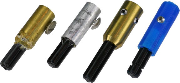
Figure B-4. Improvements in couplers. Left to right:telescoping tubing, milling machine, lathe, and 3D printer
Designing the Model
The first step in 3D printing is to create or obtain a 3D model. Think of this like making a document on a word processor before printing it to a 2D printer. Figure B-5 shows the model of the Lego motor coupler, which took about 30 minutes to design. You can download the printable file from http://www.robotroom.com/SandwichStuff.html

Figure B-5. A 3D model for a Lego cross-axle coupler designed in a CAD application
.
The model has a slot for the Lego cross axle, a hole for the set screw, a hole for the motor shaft, and a small flat area inside that hole for the flat part of the motor shaft. Both the motor shaft and set screw holes are slightly countersunk to make insertion easier. These features would require extra steps during conventional machining, but do not significantly affect print time with 3D printers.
I made the coupler model using a free online tool called Tinkercad. Not surprisingly, there are plenty of competitors, each with advantages and disadvantages. The advantage of Tinkercad is that it is free and easy to learn. The disadvantage is that the model files are stored online only, and you should always be wary of how long free tools (and your files) will be supported and available.
Adding and Subtracting
There are a variety of ways to design a 3D model. Artists and sculptors often require different techniques than do engineers. For example, a 3D game model needs to be designed for computing performance and aesthetics, whereas a robot part needs to be designed for fit and function.
For beginners, an easy to learn 3D technique is called constructive solid geometry. Put simply, you place a primitive shape, such as a cube, sphere, or cylinder, and then you either add or subtract another primitive shape. For example, take a cylinder and subtract a smaller cylinder to create a tube. See Figure B-6.

Figure B-6. Subtracting a primative 3D column creates a tube
Or, take a cylinder and subtract two rectangular boxes (cuboids) and you have a slot for the Lego cross axle. See Figure B-7.

Figure B-7. Subtracting primative 3D boxes creates a slot for a Lego cross axle
A cylinder with a perpendicular cylinder removed creates a place for a set screw. Further subtracting a perpendicular cone tapers the entry hole to make tapping screw threads easier. See Figure B-8.

Figure B-8. Subtracting a cylinder and cone for a set screw
All combined, start with a cylinder and subtract boxes, cylinders, and cones to create the coupler. See Figure B-9.

Figure B-9. Subtracting many primative shapes creates a motor coupler model
Preparing to Print
The editable model files are in a proprietary format for each modeling tool. To print them on a 3D printer, the model must be exported to a commonly understood format. Presently, STL files (STereoLithography) are the de facto standard.
The advantage of STL files is that almost all of 3D printer software packages can understand that format. In fact, there are public repositories of STL files where you can find a variety of interesting things to print, regardless of the modeling tool that originally created them and regardless of your printer. The disadvantage of STL files is that they are converted to a series of triangles, rather than the primitive shapes that you originally started with. This makes it difficult to revise or tweak a design.
In Tinkercad, the STL file can be downloaded from the application site. But, regardless of the source, the printer software must process the file for actual printing. The printer software needs to:
- Include instructions to the printer about the speed and temperature based on the type of output material
- Optionally add rafts and skirts to level the base and ensure the printed object stays connected to the base platform during printing
- Optionally add support columns for thin or floating portions of the model
- Digitally cut the 3D model into hundreds of 2D layers that will be stacked up on top of each other during printing
Obviously these details differ based on the type of printer and media. Nevertheless, the printer software converts a standard triangle-based definition of a complex shape into movement instructions that the specific printer understands.
Printing in 3D
Depending on the printer, the output file can either be copied to a media card or printed directly from the computer. Printing from the computer lets you view progress, but can destroy a print if the computer crashes or hangs.
Printing takes a while and can occasionally fail due to a part not staying in place or the media becoming clogged or stuck. Sometimes a part needs to be resized slightly or reoriented to produce a more dimensionally accurate piece.
The freshly made part may need some light machining, such as sanding or tapping screw threads. Consumer 3D printers do not yet have high enough resolution or accuracy to create fine threads, and threads are difficult to model in beginner modeling programs. So, in this example, the coupler set screw hole must have threads cut by a thread tapping tool (see Figure B-10).

Figure B-10. Tapping threads in a 3D printed coupler
Finishing the Coupler
The cross axle slot on the printed coupler is the right shape and a tight enough fit to hold a Lego cross axle without adhesive (see Figure B-11). Not only is this more attractive than the coupler in Chapter 20, but the cross axle can be forced out and replaced with one of a different length if needed.

Figure B-11. The Lego cross axle fits snugly without epoxy
The finished coupler, with the set screw and cross axle, is shown in Figure B-12.

Figure B-12. A 3D printed coupler that connects a Lego wheel to a standard motor shaft
What a minute! With a 3D printer we don’t need to use Lego wheels anymore. We can eliminate the separate coupler and design a wheel that connects directly to the motor shaft.
The model follows the same principals as the coupler: start with a cylinder and subtract and add other shapes to produce a hub with spokes. The model and the printed hub are shown in Figure B-13.

Figure B-13. A 3D model and the finished 3D printed hub
The center hole in the hub receives the motor shaft. The motor used in Sandwich includes a small flat on its shaft, giving it a D shape. By adding a small rectangular box inside the hub center hole in the model, the hub can also have a D shape (see Figure B-14). This prevents the motor shaft from spinning inside the hub, even if the set screw is slightly loose. This feature is very difficult to machine conventionally, but easy for a 3D printer.

Figure B-14. A D-shaped hole in the center of the wheel hub fits a D-shaped motor shaft
The set screw is tapped, installed, and tightened through a hole in the rim (see Figure B-15). Alternatively, the center of the hub could extend far enough out to clear the rim; however this would increase the total width of the wheel.

Figure B-15. Tapping set screw threads through a hole in the rim
Treading Lightly
To create a tread, I designed a printed tool that rotates around the center of the hub to spread rubber evenly around the rim (see Figure B-16). I applied white Sugru silicone rubber and then spread it with the tool.
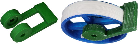
Figure B-16. A 3D printed tool for evenly applying rubber to a hub
Unfortunately, the silicon rubber doesn’t grip nearly as well as standard rubber tires. So, I tried Plasti Dip spray-on rubber. The hub was cleaned, then the sides protected with painter’s masking tape, and finally the rubber was sprayed on with four or five layers (see Figure B-17).

Figure B-17. Cleaning, masking, and spraying rubber onto the rim of a 3D printed hub
Failed again. The spray-on rubber has a better grip than the silicon rubber, but is still not good enough. Perhaps the thickness of the rubber is equally as important as the formulation? Also, air-filled rubber tires seem to have better grip than solid rubber ties, so allowing the tire to flex must be important.
Compromising with a Hybrid Wheel
According to Guinness World Records, Lego is the largest tire manufacturer in the world. Lego produces almost a million tires a day. Therefore, it seems sensible to design a wheel around their expertise.
Figure B-18 shows a Lego tire with a Lego hub alongside a Lego tire with a 3D printed hub. The printed hub includes a D-shaped motor shaft hole to match the Sandwich motor, combined with a rim that mates with a standard Lego tire. This eliminates the need for a coupler while still providing the benefit of a high-quality grip.

Figure B-18. Replicating a Lego hub with a center hole designed to mate directly with a motor
The outer dimensions of the original Lego hub were measured using a digital caliper. Figure B-19 shows how well these details are reproduced. The inner spokes and D-shaped motor shaft hole were copied from the previous attempt at making a wheel. The ability to copy and rework designs is a huge benefit of 3D printing.

Figure B-19. Matching the dimensions of an industrial-molded Lego hub on a 3D-printed hub
A large part of Sandwich’s appeal is its container. However, using a container designed for lunch and leftovers requires grinding, drilling, standoffs, and fasteners. As illustrated earlier in the chapter, a purpose-built shell can include a battery compartment and mounting holes molded into the base.
The 3D printed Sandwich body went through numerous generations as I became more proficient in modeling and printing. In Figure B-20, notice the how much the 9V battery compartment changes orientation for better balance and retention. Also, the design includes labels, such as “Sandwich” and “9V”, but transitions from cutouts to raised letters for strength. Sharp corners and slots give way to curves and holes.

Figure B-20. A progression of design improvements on the 3D printed Sandwich robot platform
To increase rigidity, a rib is included and standoffs are tapered where they meet the base (see Figure B-21). The front lip is beveled to avoid snagging on cracks on the line-following track.

Figure B-21. Rounded, tapered, raised, and relieved areas are professional touches
As a 3D model becomes more complicated, you need to be decisive of the order in which shapes are added or removed. For example, if you want the screw hole to appear both on top of the standoff and beneath the base, then the screw hole cylinder needs to be subtracted at the very end of the order (see Figure B-22). Otherwise, the cone (for the taper) or the rectangular cube (for the base) will cover up the bottom hole.

Figure B-22. The order in which shapes are combined in the model is important. Left: Adding the cone and rectangle at the end fills in half the screw hole. Right: Subtracting the hole cylinder at the end produces a screw hole throughout
Cover
The robot is completed with an opaque front baffle and a semi-transparent cover with mounting holes for switches. See Figure B-23.

Figure B-23. A black ABS baffle for the front sensors and a PET plastic case to cover the board
Compared to a leftover sandwich container, the 3D printed cover has several disadvantages. First, the 3D-printed cover is far less transparent due to reflection and refraction in the tiny filament strands in fused-filament fabrication (FFF). (There are fancier printing technologies that can create optical-quality prints.) Second, the 3D-printed cover is far more fragile than molded stretchy plastics such as polypropylene. Therefore, if you want a cover with some degree of transparency and light-weight toughness, stick with off-the-shelf containers.
Of course, the cover is optional. You can save printing time by mounting the power switch and light-dark switch directly to the PCB. Figure B-24 shows this robot in action.

Figure B-24. The open-face Sandwich robot made with 3D printed parts
Trying It Yourself
The 3D printing revolution is truly remarkable!
Three-dimensional printing opens up hobby robotics to a whole world of people that cannot afford the cost, space, or training required for a machine shop. Furthermore, 3D printing significantly reduces the time a human needs to spend producing a part, even if the printer itself will take hours.
I hope this chapter encourages you to consider downloading and printing Sandwich parts. Better still -- experiment with some designs of your own for your next robot!