
Chapter 6. Fluid Mechanics
While we stand on solid ground, we largely live in a world of fluids (liquids and gases). We walk around in a mass of air. We breathe it in our lungs and feel its pressure on our bodies. Blood flows through our body, keeping us nourished and healthy. We drink lots of water and occasionally swim in it. In the mechanical world, we use fluids like hydraulic oil to move things or we force things like cars to move through the atmosphere. We might wonder why boats and birds are streamlined, why golf balls are dimpled, what drag is, and how it’s possible to stop a car with a touch of the brake pedal. Designers frequently work with wide-ranging fluids, including water, air, oil, and blood. Their difference in behavior can be surprising.
The study of fluid behavior is broken down into two disciplines. The first is the study of fluids at rest, called fluid statics. And second is fluid dynamics, which describes the nature of moving fluids.
Fluid Behavior
Solids differ from fluids in that a fluid cannot permanently resist shear stresses. Therefore, where a solid will deform (strain) a limited amount when a force is applied, a fluid will not. The rate of movement is dictated by the force but not the total amount of movement—it just keeps on flowing. A fluid eliminates any shear stresses simply by flowing.
The resistance to flow (technically, shearing force) is called viscosity. High viscosity indicates the fluid moves slowly and takes a long time to remove shear stresses and therefore acts more like a solid. Many fluids are so viscous that they need to be heated in order to pump or atomize (molasses is one such example). Fluids are also distinctive in that pressure is transmitted equally in all directions and normal to any plane. However, pressure disturbances can be imposed upon a fluid. These disturbances move as waves that travel at an acoustic velocity, which is a function of two material properties: density and bulk modulus elasticity. Bulk modulus elasticity represents a material’s resistance to compressibility.
The inability of a fluid to handle shear stresses is actually the best definition of a fluid. Some apparently solid materials have fluid properties; that is, they gradually flow when a pressure is applied to them. In perfectly elastic materials, such as a rubber band or spring, the deformation occurs instantaneously. However, if a material is viscoelastic, it provides two different behaviors. It will elongate instantly but will then slowly flow like a viscous material.
You can measure viscoelastic behavior by quickly pulling on a material and measure the force to hold it in this stretched position. For viscoelastic materials, this value will decrease over time as the material rearranges itself. These viscoelastic materials are great at absorbing shocks and are used for such things as helmet padding. Not surprising. The cartilage that holds your bones together is viscoelastic.
A physical model of viscoelastic behavior can be developed using a combination of dashpots and springs, as shown in Figure 6-1. A dashpot is a damper that resists in proportion to velocity. It can be thought of as a piston inside a cylinder with some contact resistance so that as the piston sliding in the cylinder always drags.
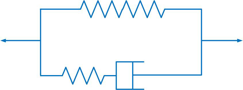
Figure 6-1. Models of viscoelastic behavior
Fluid Statics
The first law of fluid statics states that a fluid contained in a vessel, like coffee in a mug, will distribute an external pressure uniformly throughout the fluid. That is, a fluid will not have some portions in compression and others in tensions as occurs in solids. This law, referred to as Pascal’s law, applies only when the pressure produced by the fluid’s weight is neglected. In the case of hydraulic systems, this law would indicate that when one point increases in pressure, all points increase with the same pressure.
Water lies flat because the force of gravity is applied uniformly over its surface. If water were lifted up above the surrounding water, the weight of the elevated water cannot be supported by the surrounding water (specifically, the water cannot carry any of the shear stresses). Therefore, the water drops down to the same level as the remaining water. The resulting surface, called the free surface, can be affected by other external forces, besides earth’s unrelenting gravity. Wind is the principal culprit in making waves, and the gravitational pull from the sun and moon creates the tides. Additionally, water current, seismic energy, geothermal energy, and even surface tension all affect the free surface of the oceans and other bodies of water.
The pressure experienced by a water molecule increases with depth. The molecules below the free surface not only experience the earth’s gravitational pull (which is reduced by less than 1% at the bottom of the deepest oceans) but all the weight of the water above it. The gravitational pull on all the air above the free surface is small, only 14.7 psi (101 kPa or 1 bar), but the gravitational pull of the denser water molecules is much higher. The density of fluids also changes with their elevation, but it is tiny in liquids and is usually ignored.
Pneumatics and Hydraulics
Pneumatic and hydraulic system performances are dictated by pressure and the surface area upon which the pressure acts. Hydraulic and pneumatic systems rely on fluid static principles as embodied by Pascal’s law, which dictates that pressure is equally distributed throughout a container. When pressure increases at one end of a hydraulic circuit, the pressure will instantly transmit to the remote ends of the circuit. Moreover, the force exerted by the fluid can be multiplied by taking advantage of surface area.
The relationship between area and pressure is illustrated in Figure 6-2.
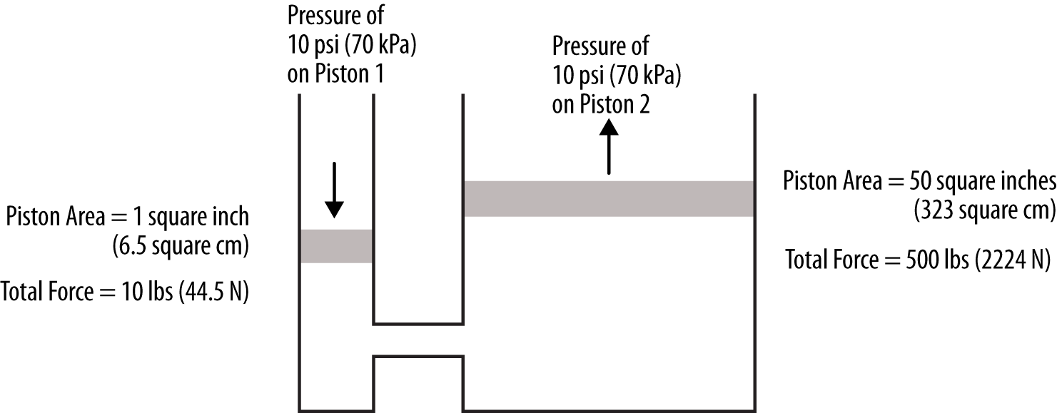
Figure 6-2. Hydraulic power
The relationship between area and pressure can be illustrated by considering the two hydraulically connected cylinders shown in Figure 6-2. We can see that because the pressures are identical, the force produced by Piston 2 is 50 times that produced by Piston 1. Because
P = F/A
where:
P = Pressure
F = Force
A = Area
And, for all the pressures being equal in the system in accordance with Pascal’s law, then:
and:
It is important to note the speed of operation is not part of this relationship. Speed is a function of fluid flow. For example, increasing the relief pressure of a hoist will not make it operate faster, it will only increase the power or work the hoist can generate.
Practical aspects of these pneumatic and hydraulic systems will be described in Chapter 10.
Fluid Dynamics
We live off the fluids flowing through our bodies; we walk through and breathe a fluid. Because we interact with flowing fluids in such a routine fashion, they are a wonderful topic of study that we call fluid dynamics. We could consider the entire fluid mechanics discipline as fluid dynamics with fluid statics being a special case where velocity is equal to zero. We could even think of fluids as being like solids, but with a really low shear strength. However, when fluids flow, all sorts of amazing things happen as pressures and velocities develop in peculiar ways.
Rheology
Fluids can respond to forces in surprising ways. We see this through rheology, which is the study of how fluids move under an applied stress, such as being pumped. We are familiar with water’s behavior—the faster you push your hand through the water the more resistance you feel. The behavior of speed and resistance has a nice linear relationship that is produced in what are called Newtonian fluids. Most fluids are Newtonian with their direct relationship between viscosity and flow rate. The shear rate can be practically thought of as the pumping speed.
However, some fluids are non-Newtonian and behave differently at different speeds, such as molasses. The common categories for non-Newtonian fluids are pseudoplastic, dilatant, and Bingham plastic. Because their viscosity is dependent on their shear (or pumping) rate, pseudoplastic fluids are also called shear-thinning and dilatants are called shear-thickening. These fluids are common in biological systems and have practical applications for power transmission, traction control, and body armor.
Liquids that are dilatant will flow easily at low speeds, but become very viscous at high speeds. A mixture of corn starch and water is the classic example of dilatant behavior. You can drag your finger slowly though and it feels like water. However, it becomes viscous if you punch it. Silly Putty is another example. You can easily stretch it, but if a load is quickly applied (a high shear rate) such as dropping it on the floor, it becomes highly viscous (like a solid) and bounces.
Dilatant behavior is typical when high concentrations of solid particles are floating in a liquid. This combination of solids and liquids is called a slurry. As slurry flows at low speeds, the whole assembly of solids and liquids flows easily, but at higher speeds the particles can’t move fast enough and makes the whole fluid assembly highly viscous.
Pseudoplastic liquids are the opposite of dilatant. They will flow easily at high speeds but become very viscous at low speeds. This is great for food! It is helpful that whipped cream can easily flow at high speeds, so too that cake mix flows nicely around spinning beaters. Molasses is another example of this behavior; it is really hard to start it moving but once you do, it is easy to flow.
Toothpaste and blood are examples of a Bingham plastic. Toothpaste won’t come out of the tube until it is squeezed. However, once the toothpaste is flowing it acts like a Newtonian fluid.
Blood is comprised of cells suspended in water-based plasma. Blood has complex flow in the body because red cells are deformed by collisions and their ability to deform allows them entry in certain capillaries. Moreover, blood will stop and start in some veins while it will flow rapidly in arterial flow. Blood at very small forces won’t move at all, but once a certain force is exceeded it will flow. This flow behavior is due to the solid blood cells being packed into the blood and it takes a force to get them moving. Even when not coagulating, the red cells tend to form structures that resist flow.
Boundary Layer
When a fluid flows over a solid, the fluid is slowed down. At the surface of the solid the fluid sticks and has no velocity. Further away from the surface, the fluid gradually flows to its full velocity. The transitional area between where the fluid sticks to a moving object and where the fluid has developed its speed is called the boundary layer.
Two types of boundary layers can develop: laminar and turbulent, as shown in Figure 6-3. In water, only small, slow-moving objects have laminar boundary layers. Turbulence is a mysterious contortion of a fluid that flails about in unpredictable ways. However, contrary to the pejorative notion of turbulence, when considering the tiny area around a surface where the boundary layer exists, a turbulent boundary layer is advantageous. A turbulent boundary layer is thinner and binds better to a flowing object than a laminar boundary layer. This stickiness of turbulent boundary layers reduces drag.
Boundary layer thickness is related to both drag and heat transfer (which will be discussed in Chapter 7).
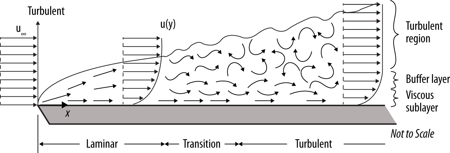
Figure 6-3. Boundary layers
Dimensionless Parameters: Mach and Reynolds Numbers
The behavior of flowing fluids is related to dimensionless parameters that relate the inertia of a fluid to some other parameter, such as viscosity. A couple of helpful dimensionless parameters are Mach and Reynolds numbers.
The Mach (Ma) number indicates if a gas has compressible or incompressible flow. High Mach flows are compressible and are handled differently than low Mach, incompressible flows. Mach number is the ratio of actual velocity to the speed of sound through the fluid:
Ma = V/a
where:
V = velocity of the gas
a = speed of sound through fluid
The speed of sound is the velocity of mechanical compression and rarefaction through a fluid; the speed of sound gives Ma= 1, which is 740 mph (330 m/s) in air. The density of low-velocity gases does not vary a great deal while for those approaching Mach 1 (the speed of sound), compression pressures cannot be distributed throughout the gas. The mathematical treatment of fluids is divided between those that can be compressed (gases traveling at low Mach) and those that cannot (high Mach gases and liquids).
The Reynolds number (Re) is a measure of the ratio of inertia to viscosity. Thinking of velocity instead of inertia in the numerator may be more intuitive. The equation takes many forms but fundamentally Reynolds number is calculated as:
Re = Inertia/Viscosity
Therefore, high-velocity flows will have a high Reynolds number while low velocity will have a low Re. Because the Reynolds number is inversely related to viscosity, high-viscosity fluids (such as oil) will have a lower Re than gasoline even if both are flowing at the same velocity.
The Reynolds number is used to determine drag and identify whether the flow is laminar or turbulent. Regardless of the fluid, Reynolds numbers less than 2000 typically result in laminar flow, while Reynolds numbers over 2300 produce turbulent flow. A transitional range exists where the flow can be either laminar or turbulent. You can see the transition from laminar to turbulent flow by running a stream from a faucet at a low flow rate and then increasing the flow until it trips into turbulent flow.
Drag
For a designer, understanding drag is probably the most important practical consideration in fluid dynamics. Total drag is the summation of three types of drag: friction, pressure, and wave making.
Water dragging against a pipe is an example of friction drag and this can be reduced by smoothing the surface or reducing fluid velocity. Pressure drag is produced by geometric changes because fluids don’t like changing direction. Therefore, pressure drag is produced when fluids are forced to do so. Consequently, gradual turns produce less pressure drag than sharp turns. You can feel the effect of pressure drag by putting your hand outside a car window while driving and noting how the resistance varies with your hand shape: open facing the wind, open in line with the wind, and a fist, for example. The same results can be seen by putting your hand under a gushing water fountain—pressure drag is a giant force and usually is the major drag component in many systems.
One example of pressure drag is seen in boats, as the water is forced to part around the hull. As shown in Figure 6-4, hull pressure drag results from the pressure difference between the front of the hull and the stern where wake eddies exist. Streamlining the hull is vitally important in reducing pressure drag. A hull that is in the shape of a box (flat bow and stern) will have 15 times as much drag as a streamlined hull (rounded bow and stern) of the same width. With a squared off bow and stern, the bow impacts the water creating high pressure, and then radically disengages the water at the stern, thereby producing powerful eddies. These eddies result in very low pressure behind the hull.
The combination of flat bow and stern features creates a large pressure differential and results in pressure drag across the hull. The streamlined hull gently changes the water direction around the bow and decreases the pressure at the bow. More importantly, it allows the water to recombine astern with a minimum of eddies and subsequent low pressure. Therefore, the streamlined hull produces a lower pressure at the bow and a higher pressure at the stern. Consequently, the pressure differential across the hull is much lower, creating a lower pressure drag.
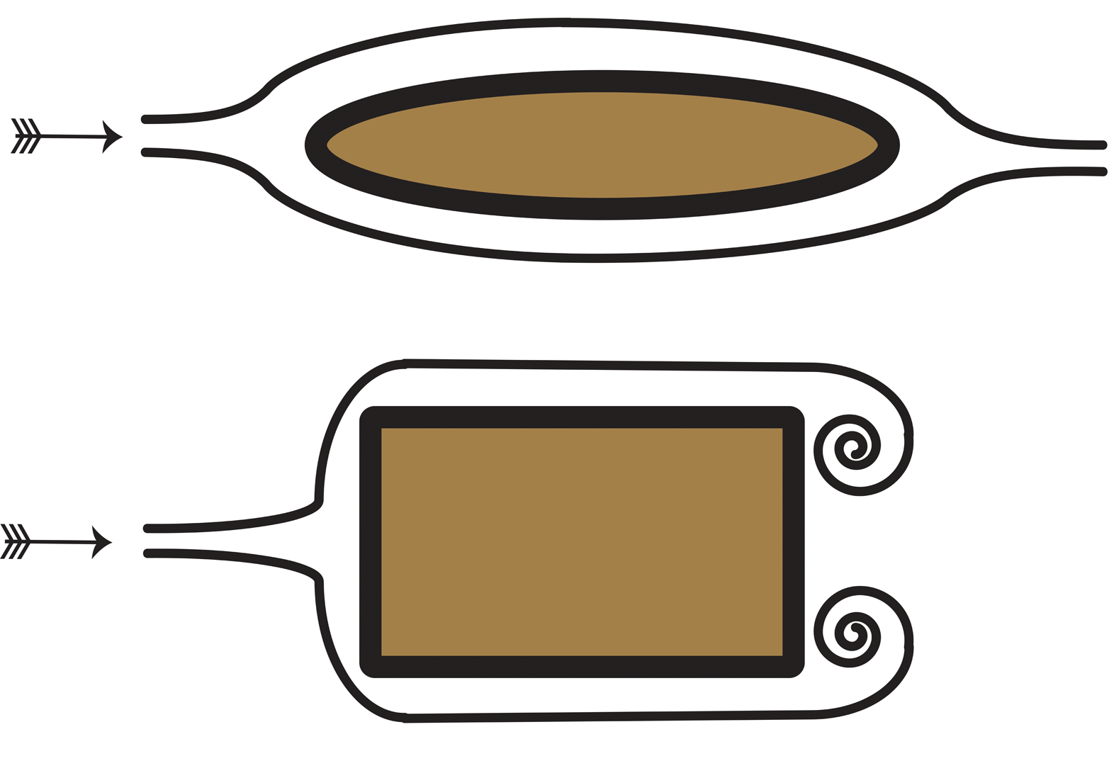
Figure 6-4. Hull drag forces
Drag Coefficient
The drag coefficient (Cd) is a convenient nondimensional parameter for relating drag to shape. Figure 6-5 provides a listing of drag coefficients for different shapes. The calculation is described by the following equation, which shows the linearly proportionality of drag force to drag coefficient:
where:
Cd = Drag coefficient
Fd = Drag force
ρ = Fluid density
v = Speed of object with respect to the fluid
A = Object’s projected area
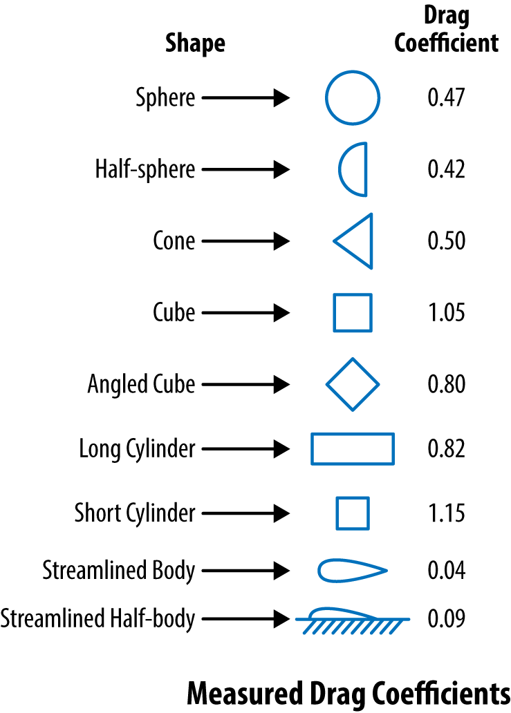
Figure 6-5. Drag coefficients of different shapes
Boundary Layer Separation
One factor affecting pressure drag is the separation of the boundary layer from a surface. Because the turbulent boundary layer is thin, it doesn’t get pulled away from a surface as readily as a thick, laminar boundary layer. The longer adhesion of the turbulent boundary layer reduces the pressure drag because it decreases the size and strength of the deleterious wake turbulence.
In the case of a sphere, the boundary layer separation point for a turbulent boundary is about 120° from the impact point, versus only about 80° for the laminar boundary layer. What does this mean? With the laminar boundary layer, a large wake is produced with strong eddies. With the turbulent boundary layer, the wake is reduced. Therefore, the pressure drag is greatly decreased.
The dynamics of air separation and the vortexes produced by it have led to dramatic structural failure when the shedding of the boundary layer on either side of an object produces an oscillating motion. This vortex shedding phenomenon caused the failure of the Tacoma Narrows Bridge and the tower failure of an amusement park ride at Cedar Point in Sandusky, Ohio.
Wave Drag
When water is lifted up in the form of a wave, it works against gravity and therefore uses energy, as shown in Figure 6-6. This is wave drag and you see these in such examples as the bow and stern of boats and river pilings. The energy wasted in producing these waves is called wave-making drag and is only an issue in open flow systems like boats and drainage channels.
Figure 6-6. Water is lifted up as it flows into the piling
We should be humbled when studying drag by considering a commonly used equation for pressure drop produced in a pipe. This is an old, well-understood, and important equation. The formula is called the Hazen–Williams formula and it is used for filled, round pipe with turbulent flow. While it looks a bit nasty with all the nonintegral exponents, it is this very feature that illustrates the difference between theory and reality.
Pressure drop per foot in psi:
where:
Q = flow rate in gallons per minute
C = pipe roughness coefficient (e.g., copper = 140)
d = inside diameter of pipe in inches
Closing Thoughts
Fluid mechanics seems to have the most bizarre names, which can take the joy out of describing how cookie dough and drinking fountains behave. You know most all fluid dynamics issues can be divided between those above and below Mach 1 and a Reynolds number of 2000. You know air can act nearly like a liquid and flow behavior changes dramatically with turbulent flow.
You know that drag is complex. Often, you want some surface roughness to cause a turbulent boundary layer to form, as this layer will be stickier and reduce pressure drag. You also know the surface properties of fluids produce resistance to flow and some fluids are non-Newtonian and do not act like water and air.
For a designer, fluid dynamics comes down to knowing that a slow design has less drag. If your design cannot go slowly, shape is usually more important than smoothness. You also need to understand the behavior of the fluid—some will change their behavior as they move faster.
If you are designing a boat, you want it to have nearly the same pressure at the front and back so you shape it like a fish, not a brick. You want smooth sides and gradual changes in direction. You know the static pressure on the underwater hull is huge. You know as the speed increases, shape becomes even more important.
If you are designing an automatic painting system, you know the first step is to understand how the paint behaves when it is pumped quickly versus slowly. You need to think how you are going to clean the paint out of the lines also!