
Chapter 6. The “Hello World” of TinyML: Deploying to Microcontrollers
Now it’s time to get our hands dirty. Over the course of this chapter, we will deploy the code to three different devices:
We’ll walk through the build and deployment process for each one.
Note
TensorFlow Lite regularly adds support for new devices, so if the device you’d like to use isn’t listed here, it’s worth checking the example’s README.md.
You can also check there for updated deployment instructions if you run into trouble following these steps.
Every device has its own unique output capabilities, ranging from a bank of LEDs to a full LCD display, so the example contains a custom implementation of HandleOutput() for each one. We’ll also walk through each of these and talk about how its logic works. Even if you don’t have all of the devices, reading through this code should be interesting, so we strongly recommend taking a look.
What Exactly Is a Microcontroller?
Depending on your past experience, you might not be familiar with how microcontrollers interact with other electronic components. Because we’re about to start playing with hardware, it’s worth introducing some ideas before we move along.
On a microcontroller board like the Arduino, SparkFun Edge, or STM32F746G Discovery kit, the actual microcontroller is just one of many electronic components attached to the circuit board. Figure 6-1 shows the microcontroller on the SparkFun Edge.

Figure 6-1. The SparkFun Edge board with its microcontroller highlighted
The microcontroller is connected to the circuit board it lives on using pins. A typical microcontroller has dozens of pins, and they serve all sorts of purposes. Some provide power to the microcontroller; others connect it to various important components. Some pins are set aside for the input and output of digital signals by programs running on the microcontroller. These are called GPIO pins, which stands for general-purpose input/output. They can act as inputs, determining whether a voltage is being applied to them, or outputs, sourcing current that can power or communicate with other components.
GPIO pins are digital. This means that in output mode, they are like switches that can either be fully on, or fully off. In input mode, they can detect whether the voltage applied to them by another component is either above or below a certain threshold.
In addition to GPIOs, some microcontrollers have analog input pins, which can measure the exact level of voltage that is being applied to them.
By calling special functions, the program running on a microcontroller can control whether a given pin is in input or output mode. Other functions are used to switch an output pin on or off, or to read the current state of an input pin.
Now that you know a bit more about microcontrollers, let’s take a closer look at our first device: the Arduino.
Arduino
There are a huge variety of Arduino boards, all with different capabilities. Not all of them will run TensorFlow Lite for Microcontrollers. The board we recommend for this book is the Arduino Nano 33 BLE Sense. In addition to being compatible with TensorFlow Lite, it also includes a microphone and an accelerometer (which we use in later chapters). We recommend buying the version of the board with headers, which makes it easier to connect other components without soldering.
Most Arduino boards come with a built-in LED, and this is what we’ll be using to visually output our sine values. Figure 6-2 shows an Arduino Nano 33 BLE Sense board with the LED highlighted.

Figure 6-2. The Arduino Nano 33 BLE Sense board with the LED highlighted
Handling Output on Arduino
Because we have only one LED to work with, we need to think creatively. One option is to vary the brightness of the LED based on the most recently predicted sine value. Given that the value ranges from –1 to 1, we could represent 0 with an LED that is fully off, –1 and 1 with a fully lit LED, and any intermediate values with a partially dimmed LED. As the program runs inferences in a loop, the LED will fade repeatedly on and off.
We can vary the number of inferences we perform across a full sine wave cycle using the kInferencesPerCycle constant. Because one inference takes a set amount of time, tweaking kInferencesPerCycle, defined in constants.cc, will adjust how fast the LED fades.
There’s an Arduino-specific version of this file in hello_world/arduino/constants.cc. The file has been given the same name as hello_world/constants.cc, so it will be used instead of the original implementation when the application is built for Arduino.
To dim our built-in LED, we can use a technique called pulse width modulation (PWM). If we switch an output pin on and off extremely rapidly, the pin’s output voltage becomes a factor of the ratio between time spent in the off and on states. If the pin spends 50% of the time in each state, its output voltage will be 50% of its maximum. If it spends 75% in the on state and 25% in the off state, its voltage will be 75% of its maximum.
PWM is only available on certain pins of certain Arduino devices, but it’s very easy to use: we just call a function that sets our desired output level for the pin.
The code that implements output handling for Arduino is in hello_world/arduino/output_handler.cc, which is used instead of the original file, hello_world/output_handler.cc.
Let’s walk through the source:
#include "tensorflow/lite/micro/examples/hello_world/output_handler.h"#include "Arduino.h"#include "tensorflow/lite/micro/examples/hello_world/constants.h"
First, we include some header files. Our output_handler.h specifies the interface for this file. Arduino.h provides the interface for the Arduino platform; we use this to control the board. Because we need access to kInferencesPerCycle, we also include constants.h.
Next, we define the function and instruct it what to do the first time it runs:
// Adjusts brightness of an LED to represent the current y valuevoidHandleOutput(tflite::ErrorReporter*error_reporter,floatx_value,floaty_value){// Track whether the function has run at least oncestaticboolis_initialized=false;// Do this only onceif(!is_initialized){// Set the LED pin to outputpinMode(LED_BUILTIN,OUTPUT);is_initialized=true;}
In C++, a variable declared as static within a function will hold its value across multiple runs of the function. Here, we use the is_initialized variable to track whether the code in the following if (!is_initialized) block has ever been run before.
The initialization block calls Arduino’s pinMode() function, which indicates to the microcontroller whether a given pin should be in input or output mode. This is necessary before using a pin. The function is called with two constants defined by the Arduino platform: LED_BUILTIN and OUTPUT. LED_BUILTIN represents the pin connected to the board’s built-in LED, and OUTPUT represents output mode.
After configuring the built-in LED’s pin to output mode, set is_initialized to true so that this block code will not run again.
Next up, we calculate the desired brightness of the LED:
// Calculate the brightness of the LED such that y=-1 is fully off// and y=1 is fully on. The LED's brightness can range from 0-255.intbrightness=(int)(127.5f*(y_value+1));
The Arduino allows us to set the level of a PWM output as a number from 0 to 255, where 0 means fully off and 255 means fully on. Our y_value is a number between –1 and 1. The preceding code maps y_value to the range 0 to 255 so that when y = -1 the LED is fully off, when y = 0 the LED is half lit, and when y = 1 the LED is fully lit.
The next step is to actually set the LED’s brightness:
// Set the brightness of the LED. If the specified pin does not support PWM,// this will result in the LED being on when y > 127, off otherwise.analogWrite(LED_BUILTIN,brightness);
The Arduino platform’s analogWrite() function takes a pin number (we provide LED_BUILTIN) and a value between 0 and 255. We provide our brightness, calculated in the previous line. When this function is called, the LED will be lit at that level.
Note
Unfortunately, on some models of Arduino boards, the pin that the built-in LED is connected to is not capable of PWM. This means our calls to analogWrite() won’t vary its brightness. Instead, the LED will be switched on if the value passed into analogWrite() is above 127, and switched off if it is 126 or below. This means the LED will flash on and off instead of fading. Not quite as cool, but it still demonstrates our sine wave prediction.
Finally, we use the ErrorReporter instance to log the brightness value:
// Log the current brightness value for display in the Arduino plottererror_reporter->Report("%d",brightness);
On the Arduino platform, the ErrorReporter is set up to log data via a serial port. Serial is a very common way for microcontrollers to communicate with host computers, and it’s often used for debugging. It’s a communication protocol in which data is communicated one bit at a time by switching an output pin on and off. We can use it to send and receive anything, from raw binary data to text and numbers.
The Arduino IDE contains tools for capturing and displaying data received through a serial port. One of the tools, the Serial Plotter, can display a graph of values it receives via serial. By outputting a stream of brightness values from our code, we’ll be able to see them graphed. Figure 6-3 shows this in action.

Figure 6-3. The Arduino IDE’s Serial Plotter
We provide instructions on how to use the Serial Plotter later in this section.
Note
You might be wondering how the ErrorReporter is able to output data via Arduino’s serial interface. You can find the code implementation in micro/arduino/debug_log.cc. It replaces the original implementation at micro/debug_log.cc. Just like how output_handler.cc is overwritten, we can provide platform-specific implementations of any source file in TensorFlow Lite for Microcontrollers by adding them to a directory with the platform’s name.
Running the Example
Our next task is to build the project for Arduino and deploy it to a device.
Tip
There’s always a chance that the build process might have changed since this book was written, so check README.md for the latest instructions.
Here’s everything that we’ll need:
-
A supported Arduino board (we recommend the Arduino Nano 33 BLE Sense)
-
The appropriate USB cable
-
The Arduino IDE (you’ll need to download and install this before continuing)
The projects in this book are available as example code in the TensorFlow Lite Arduino library, which you can easily install via the Arduino IDE and select Manage Libraries from the Tools menu. In the window that appears, search for and install the library named Arduino_TensorFlowLite. You should be able to use the latest version, but if you run into issues, the version that was tested with this book is 1.14-ALPHA.
Note
You can also install the library from a .zip file, which you can either download from the TensorFlow Lite team or generate yourself using the TensorFlow Lite for Microcontrollers Makefile. If you’d prefer to do this, see Appendix A.
After you’ve installed the library, the hello_world example will show up in the File menu under Examples→Arduino_TensorFlowLite, as shown in Figure 6-4.
Click “hello_world” to load the example. It will appear as a new window, with a tab for each of the source files. The file in the first tab, hello_world, is equivalent to the main_functions.cc we walked through earlier.
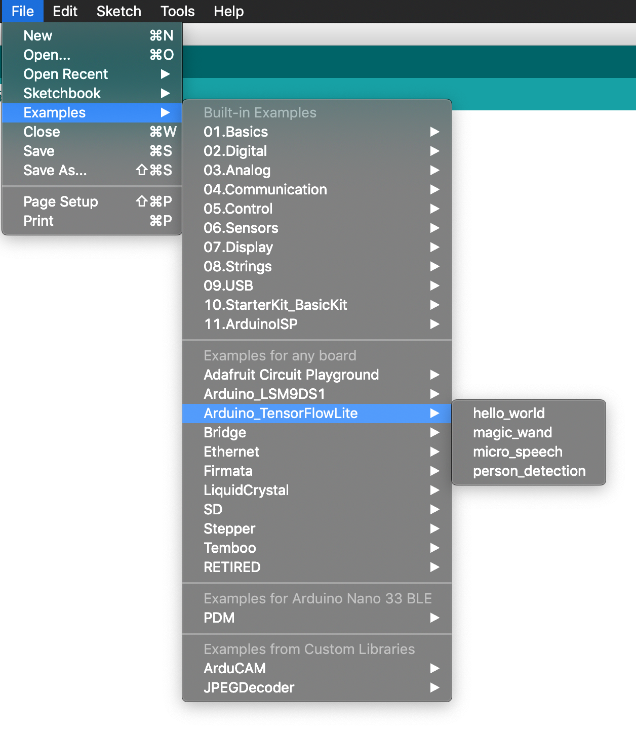
Figure 6-4. The Examples menu
To run the example, plug in your Arduino device via USB. Make sure the correct device type is selected from the Board drop-down list in the Tools menu, as shown in Figure 6-5.
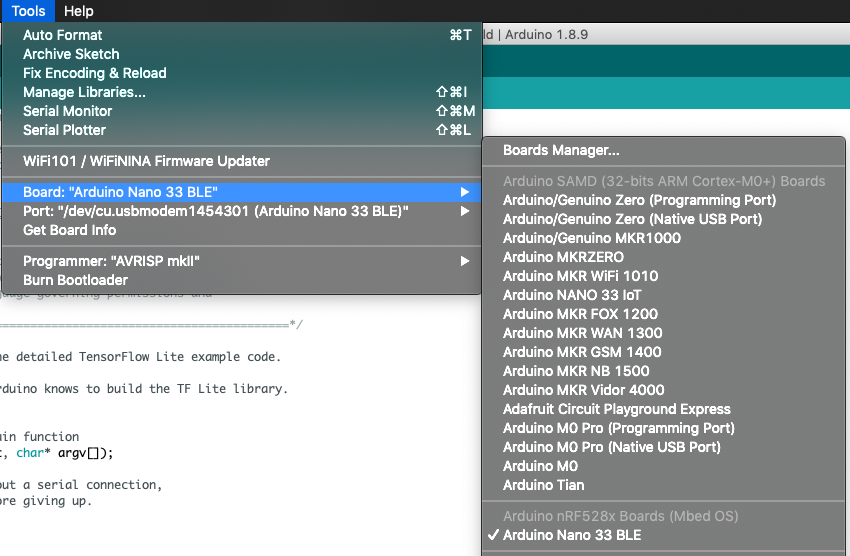
Figure 6-5. The Board drop-down list
If your device’s name doesn’t appear in the list, you’ll need to install its support package. To do this, click Boards Manager. In the window that appears, search for your device and install the latest version of the corresponding support package.
Next, make sure the device’s port is selected in the Port drop-down list, also in the Tools menu, as shown in Figure 6-6.
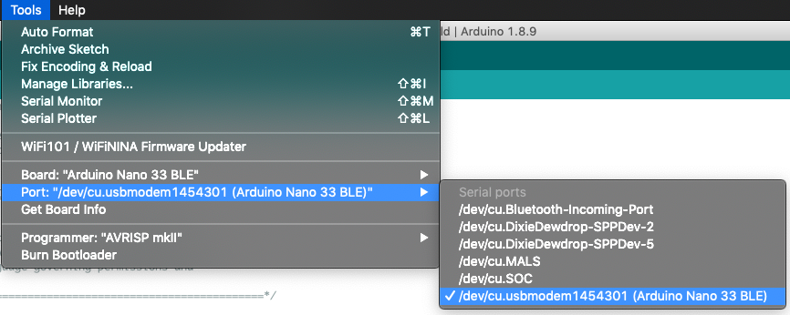
Figure 6-6. The Port drop-down list
Finally, in the Arduino window, click the upload button (highlighted in white in Figure 6-7) to compile and upload the code to your Arduino device.
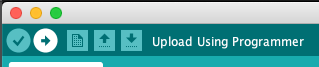
Figure 6-7. The upload button, a right-facing arrow
After the upload has successfully completed you should see the LED on your Arduino board begin either fading in and out or flashing on and off, depending on whether the pin it is attached to supports PWM.
Congratulations: you’re running ML on-device!
Note
Different models of Arduino boards have different hardware, and will run inference at varying speeds. If your LED is either flickering or stays fully on, you might need to increase the number of inferences per cycle. You can do this via the kInferencesPerCycle constant in arduino_constants.cpp.
“Making Your Own Changes” shows you how to edit the example’s code.
You can also view the brightness value plotted on a graph. To do this, open the Arduino IDE’s Serial Plotter by selecting it in the Tools menu, as shown in Figure 6-8.

Figure 6-8. The Serial Plotter menu option
The plotter shows the value as it changes over time, as demonstrated in Figure 6-9.
Figure 6-9. The Serial Plotter graphing the value
To view the raw data that is received from the Arduino’s serial port, open the Serial Monitor from the Tools menu. You’ll see a stream of numbers flying past, like in Figure 6-10.

Figure 6-10. The Serial Monitor displaying raw data
Making Your Own Changes
Now that you’ve deployed the application, it might be fun to play around and make some changes to the code. You can edit the source files in the Arduino IDE. When you save, you’ll be prompted to resave the example in a new location. When you’re done making changes, you can click the upload button in the Arduino IDE to build and deploy.
To get started making changes, here are a few experiments you could try:
SparkFun Edge
The SparkFun Edge development board was designed specifically as a platform for experimenting with machine learning on tiny devices. It has a power-efficient Ambiq Apollo 3 microcontroller with an Arm Cortex M4 processor core.
It features a bank of four LEDs, as shown in Figure 6-11. We use these to visually output our sine values.

Figure 6-11. The SparkFun Edge’s four LEDs
Handling Output on SparkFun Edge
We can use the board’s bank of LEDs to make a simple animation, because nothing says cutting-edge AI like blinkenlights.
The LEDs (red, green, blue, and yellow) are physically lined up in the following order:
[ R G B Y ]
The following table represents how we will light the LEDs for different y values:
| Range | LEDs lit |
|---|---|
|
|
|
|
|
|
|
|
|
|
Each inference takes a certain amount of time, so tweaking kInferencesPerCycle, defined in constants.cc, will adjust how fast the LEDs cycle.
Figure 6-12 shows a still from an animated .gif of the program running.

Figure 6-12. A still from the animation of the SparkFun Edge’s LEDs
The code that implements output handling for the SparkFun Edge is in hello_world/sparkfun_edge/output_handler.cc, which is used instead of the original file, hello_world/output_handler.cc.
Let’s start walking through it:
#include "tensorflow/lite/micro/examples/hello_world/output_handler.h"#include "am_bsp.h"
First, we include some header files. Our output_handler.h specifies the interface for this file. The other file, am_bsp.h, comes from something called the Ambiq Apollo3 SDK. Ambiq is the manufacturer of the SparkFun Edge’s microcontroller, which is called the Apollo3. The SDK (short for software development kit) is a collection of source files that define constants and functions that can be used to control the microcontroller’s features.
Because we are planning to control the board’s LEDs, we need to be able to switch the microcontroller’s pins on and off. This is what we use the SDK for.
Note
The Makefile will automatically download the SDK when we eventually build the project. If you’re curious, you can read more about it or download the code to explore on SparkFun’s website.
Next, we define the HandleOutput() function and indicate what to do on its first run:
voidHandleOutput(tflite::ErrorReporter*error_reporter,floatx_value,floaty_value){// The first time this method runs, set up our LEDs correctlystaticboolis_initialized=false;if(!is_initialized){// Set up LEDs as outputsam_hal_gpio_pinconfig(AM_BSP_GPIO_LED_RED,g_AM_HAL_GPIO_OUTPUT_12);am_hal_gpio_pinconfig(AM_BSP_GPIO_LED_BLUE,g_AM_HAL_GPIO_OUTPUT_12);am_hal_gpio_pinconfig(AM_BSP_GPIO_LED_GREEN,g_AM_HAL_GPIO_OUTPUT_12);am_hal_gpio_pinconfig(AM_BSP_GPIO_LED_YELLOW,g_AM_HAL_GPIO_OUTPUT_12);// Ensure all pins are clearedam_hal_gpio_output_clear(AM_BSP_GPIO_LED_RED);am_hal_gpio_output_clear(AM_BSP_GPIO_LED_BLUE);am_hal_gpio_output_clear(AM_BSP_GPIO_LED_GREEN);am_hal_gpio_output_clear(AM_BSP_GPIO_LED_YELLOW);is_initialized=true;}
Phew, that’s a lot of setup! We’re using the am_hal_gpio_pinconfig() function, provided by am_bsp.h, to configure the pins connected to the board’s built-in LEDs, putting them into output mode (represented by the g_AM_HAL_GPIO_OUTPUT_12 constant). The pin number of each LED is represented by a constant, such as AM_BSP_GPIO_LED_RED.
We then clear all of the outputs using am_hal_gpio_output_clear(), so the LEDs are all switched off. As in the Arduino implementation, we use a static variable named is_initialized to ensure the code in this block is run only once. Next, we determine which LEDs should be lit if the y value is negative:
// Set the LEDs to represent negative valuesif(y_value<0){// Clear unnecessary LEDsam_hal_gpio_output_clear(AM_BSP_GPIO_LED_GREEN);am_hal_gpio_output_clear(AM_BSP_GPIO_LED_YELLOW);// The blue LED is lit for all negative valuesam_hal_gpio_output_set(AM_BSP_GPIO_LED_BLUE);// The red LED is lit in only some casesif(y_value<=-0.75){am_hal_gpio_output_set(AM_BSP_GPIO_LED_RED);}else{am_hal_gpio_output_clear(AM_BSP_GPIO_LED_RED);}
First, in case the y value only just became negative, we clear the two LEDs that are used to indicate positive values. Next, we call am_hal_gpio_output_set() to switch on the blue LED, which will always be lit if the value is negative. Finally, if the value is less than –0.75, we switch on the red LED. Otherwise, we switch it off.
Next up, we do the same thing but for positive values of y:
// Set the LEDs to represent positive values}elseif(y_value>0){// Clear unnecessary LEDsam_hal_gpio_output_clear(AM_BSP_GPIO_LED_RED);am_hal_gpio_output_clear(AM_BSP_GPIO_LED_BLUE);// The green LED is lit for all positive valuesam_hal_gpio_output_set(AM_BSP_GPIO_LED_GREEN);// The yellow LED is lit in only some casesif(y_value>=0.75){am_hal_gpio_output_set(AM_BSP_GPIO_LED_YELLOW);}else{am_hal_gpio_output_clear(AM_BSP_GPIO_LED_YELLOW);}}
That’s just about it for the LEDs. The last thing we do is log the current output values to anyone who is listening on the serial port:
// Log the current X and Y valueserror_reporter->Report("x_value: %f, y_value: %f",x_value,y_value);
Note
Our ErrorReporter is able to output data via the SparkFun Edge’s serial interface due to a custom implementation of micro/sparkfun_edge/debug_log.cc that replaces the original implementation at mmicro/debug_log.cc.
Running the Example
Now we can build the sample code and deploy it to the SparkFun Edge.
Tip
There’s always a chance that the build process might have changed since this book was written, so check README.md for the latest instructions.
To build and deploy our code, we’ll need the following:
-
A SparkFun Edge board
-
A USB programmer (we recommend the SparkFun Serial Basic Breakout, which is available in micro-B USB and USB-C variants)
-
A matching USB cable
-
Python 3 and some dependencies
To begin, open a terminal, clone the TensorFlow repository, and then change into its directory:
git clone https://github.com/tensorflow/tensorflow.git
cd tensorflow
Next, we’re going to build the binary and run some commands that get it ready for downloading to the device. To avoid some typing, you can copy and paste these commands from README.md.
Build the binary
The following command downloads all the required dependencies and then compiles a binary for the SparkFun Edge:
make -f tensorflow/lite/micro/tools/make/MakefileTARGET=sparkfun_edge hello_world_bin
Note
A binary is a file that contains the program in a form that can be run directly by the SparkFun Edge hardware.
The binary will be created as a .bin file, in the following location:
tensorflow/lite/micro/tools/make/gen/
To check that the file exists, you can use the following command:
test-f tensorflow/lite/micro/tools/make/gen/sparkfun_edge_cortex-m4/bin/hello_world.bin&&echo"Binary was successfully created"||echo"Binary is missing"
If you run that command, you should see Binary was successfully created printed to the console.
If you see Binary is missing, there was a problem with the build process. If so, it’s likely that you can find some clues to what went wrong in the output of the make command.
Sign the binary
The binary must be signed with cryptographic keys to be deployed to the device. Let’s now run some commands that will sign the binary so it can be flashed to the SparkFun Edge. The scripts used here come from the Ambiq SDK, which is downloaded when the Makefile is run.
Enter the following command to set up some dummy cryptographic keys that you can use for development:
cp tensorflow/lite/micro/tools/make/downloads/AmbiqSuite-Rel2.0.0/tools/apollo3_scripts/keys_info0.pytensorflow/lite/micro/tools/make/downloads/AmbiqSuite-Rel2.0.0/tools/apollo3_scripts/keys_info.py
Next, run the following command to create a signed binary. Substitute python3 with python if necessary:
python3 tensorflow/lite/micro/tools/make/downloads/AmbiqSuite-Rel2.0.0/tools/apollo3_scripts/create_cust_image_blob.py--bin tensorflow/lite/micro/tools/make/gen/sparkfun_edge_cortex-m4/bin/hello_world.bin--load-address 0xC000--magic-num 0xCB -o main_nonsecure_ota--version 0x0
This creates the file main_nonsecure_ota.bin. Now run this command to create a final version of the file that you can use to flash your device with the script you will use in the next step:
python3 tensorflow/lite/micro/tools/make/downloads/AmbiqSuite-Rel2.0.0/tools/apollo3_scripts/create_cust_wireupdate_blob.py--load-address 0x20000--bin main_nonsecure_ota.bin-i6-o main_nonsecure_wire--options 0x1
You should now have a file called main_nonsecure_wire.bin in the directory where you ran the commands. This is the file you’ll be flashing to the device.
Flash the binary
The SparkFun Edge stores the program it is currently running in its 1 megabyte of flash memory. If you want the board to run a new program, you need to send it to the board, which will store it in flash memory, overwriting any program that was previously saved.
This process is called flashing. Let’s walk through the steps.
Attach the programmer to the board
To download new programs to the board, you’ll use the SparkFun USB-C Serial Basic serial programmer. This device allows your computer to communicate with the microcontroller via USB.
To attach this device to your board, perform the following steps:
-
On the side of the SparkFun Edge, locate the six-pin header.
-
Plug the SparkFun USB-C Serial Basic into these pins, ensuring that the pins labeled BLK and GRN on each device are lined up correctly.
You can see the correct arrangement in Figure 6-13.
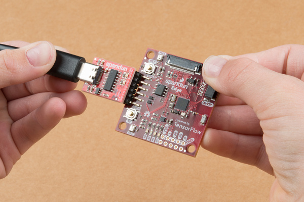
Figure 6-13. Connecting the SparkFun Edge and USB-C Serial Basic (courtesy of SparkFun)
Attach the programmer to your computer
Next, connect the board to your computer via USB. To program the board, you need to determine the name that your computer gives the device. The best way of doing this is to list all of the computer’s devices before and after attaching it and then look to see which device is new.
Warning
Some people have reported issues with their operating system’s default drivers for the programmer, so we strongly recommend installing the driver before you continue.
Before attaching the device via USB, run the following command:
# macOS:ls /dev/cu*# Linux:ls /dev/tty*
This should output a list of attached devices that looks something like the following:
/dev/cu.Bluetooth-Incoming-Port
/dev/cu.MALS
/dev/cu.SOC
Now, connect the programmer to your computer’s USB port and run the command again:
# macOS:ls /dev/cu*# Linux:ls /dev/tty*
You should see an extra item in the output, as in the example that follows. Your new item might have a different name. This new item is the name of the device:
/dev/cu.Bluetooth-Incoming-Port
/dev/cu.MALS
/dev/cu.SOC
/dev/cu.wchusbserial-1450
This name will be used to refer to the device. However, it can change depending on which USB port the programmer is attached to, so if you disconnect the board from your computer and then reattach it, you might need to look up its name again.
Tip
Some users have reported two devices appearing in the list. If you see two devices, the correct one to use begins with the letters “wch”; for example, “/dev/wchusbserial-14410.”
After you’ve identified the device name, put it in a shell variable for later use:
export DEVICENAME=<your device name here>
This is a variable that you can use when running commands that require the device name, later in the process.
Run the script to flash your board
To flash the board, you need to put it into a special “bootloader” state that prepares it to receive the new binary. You can then run a script to send the binary to the board.
First create an environment variable to specify the baud rate, which is the speed at which data will be sent to the device:
exportBAUD_RATE=921600
Now paste the command that follows into your terminal—but do not press Enter yet!. The ${DEVICENAME} and ${BAUD_RATE} in the command will be replaced with the values you set in the previous sections. Remember to substitute python3 with python if necessary:
python3 tensorflow/lite/micro/tools/make/downloads/AmbiqSuite-Rel2.0.0/tools/apollo3_scripts/uart_wired_update.py -b${BAUD_RATE}${DEVICENAME}-r1-f main_nonsecure_wire.bin -i 6
Next, you’ll reset the board into its bootloader state and flash the board. On the board, locate the buttons marked RST and 14, as shown in Figure 6-14.
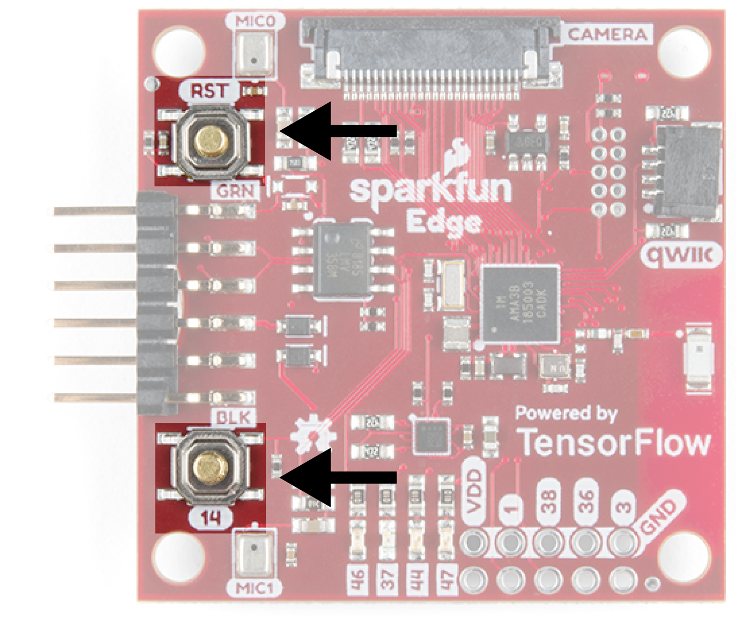
Figure 6-14. The SparkFun Edge’s buttons
Perform the following steps:
-
Ensure that your board is connected to the programmer and that the entire thing is connected to your computer via USB.
-
On the board, press and hold the button marked
14. Continue holding it. -
While still holding the button marked
14, press the button markedRSTto reset the board. -
Press Enter on your computer to run the script. Continue holding button
14.
You should now see something like the following appearing on your screen:
Connecting with Corvette over serial port /dev/cu.usbserial-1440...
Sending Hello.
Received response for Hello
Received Status
length =  0x58
version =  0x3
Max Storage =  0x4ffa0
Status =  0x2
State =  0x7
AMInfo =
0x1
0xff2da3ff
0x55fff
0x1
0x49f40003
0xffffffff
[...lots more 0xffffffff...]
Sending OTA Descriptor =  0xfe000
Sending Update Command.
number of updates needed =  1
Sending block of size  0x158b0  from  0x0  to  0x158b0
Sending Data Packet of length  8180
Sending Data Packet of length  8180
[...lots more Sending Data Packet of length  8180...]
Keep holding button 14 until you see Sending Data Packet of length 8180.
You can release the button after seeing this (but it’s okay if you keep holding it).
The program will continue to print lines on the terminal. Eventually you will see something like the following:
[...lots more Sending Data Packet of length  8180...]
Sending Data Packet of length  8180
Sending Data Packet of length  6440
Sending Reset Command.
Done.
This indicates a successful flashing.
Viewing Debug Data
Debug information is logged by the board while the program is running. To view it, we can monitor the board’s serial port output using a baud rate of 115200. On macOS and Linux, the following command should work:
screen${DEVICENAME}115200
You will see a lot of output flying past! To stop the scrolling, press Ctrl-A, immediately followed by Esc. You can then use the arrow keys to explore the output, which will contain the results of running inference on various x values:
x_value: 1.1843798*2^2, y_value: -1.9542645*2^-1
To stop viewing the debug output with screen, press Ctrl-A, immediately followed by the K key, and then press the Y key.
Note
The program screen is a helpful utility program for connecting to other computers. In this case, we’re using it to listen to the data the SparkFun Edge board is logging via its serial port. If you’re using Windows, you could try using the program CoolTerm to do the same thing.
Making Your Own Changes
Now that you’ve deployed the basic application, try playing around and making some changes. You can find the application’s code in the tensorflow/lite/micro/examples/hello_world folder. Just edit and save, and then repeat the previous instructions to deploy your modified code to the device.
Here are a few things you could try:
ST Microelectronics STM32F746G Discovery Kit
The STM32F746G is a microcontroller development board with a relatively powerful Arm Cortex-M7 processor core.
This board runs Arm’s Mbed OS, an embedded operating system designed to make it easier to build and deploy embedded applications. This means that we can use many of the instructions in this section to build for other Mbed devices.
The STM32F746G comes with an attached LCD screen, which will allow us to build a much more elaborate visual display.
Handling Output on STM32F746G
Now that we have an entire LCD to play with, we can draw a nice animation. Let’s use the x-axis of the screen to represent number of inferences, and the y-axis to represent the current value of our prediction.
We’ll draw a dot where this value should be, and it will move around the screen as we loop through the input range of 0 to 2π. Figure 6-15 presents a wireframe of this.
Each inference takes a certain amount of time, so tweaking kInferencesPerCycle, defined in constants.cc, will adjust the speed and smoothness of the dot’s motion.
Figure 6-16 shows a still from an animated .gif of the program running.

Figure 6-15. The animation we’ll draw on the LCD display
Figure 6-16 shows a still from an animated .gif of the program running.

Figure 6-16. The code running on an STM32F746G Discovery kit, which has an LCD display
The code that implements output handling for the STM32F746G is in hello_world/disco_f746ng/output_handler.cc, which is used instead of the original file, hello_world/output_handler.cc.
Let’s walk through it:
#include "tensorflow/lite/micro/examples/hello_world/output_handler.h"#include "LCD_DISCO_F746NG.h"#include "tensorflow/lite/micro/examples/hello_world/constants.h"
First, we have some header files. Our output_handler.h specifies the interface for this file. LCD_DISCO_F74NG.h, supplied by the board’s manufacturer, declares the interface we will use to control its LCD screen. We also include constants.h, since we need access to kInferencesPerCycle and kXrange.
Next, we set up a ton of variables. First comes an instance of LCD_DISCO_F746NG, which is defined in LCD_DISCO_F74NG.h and provides methods that we can use to control the LCD:
// The LCD driverLCD_DISCO_F746NGlcd;
Details on the LCD_DISCO_F746NG classes are available on the Mbed site.
Next, we define some constants that control the look and feel of our visuals:
// The colors we'll drawconstuint32_tbackground_color=0xFFF4B400;// Yellowconstuint32_tforeground_color=0xFFDB4437;// Red// The size of the dot we'll drawconstintdot_radius=10;
The colors are provided as hex values, like 0xFFF4B400. They are in the format AARRGGBB, where AA represents the alpha value (or opacity, with FF being fully opaque), and RR, GG, and BB represent the amounts of red, green, and blue.
Tip
With some practice, you can learn to read the color from the hex value. 0xFFF4B400 is fully opaque and has a lot of red and a fair amount of green, which makes it a nice orange-yellow.
You can also look up the values with a quick Google search.
We then declare a few more variables that define the shape and size of our animation:
// Size of the drawable areaintwidth;intheight;// Midpoint of the y axisintmidpoint;// Pixels per unit of x_valueintx_increment;
After the variables, we define the HandleOutput() function and tell it what to do on its first run:
// Animates a dot across the screen to represent the current x and y valuesvoidHandleOutput(tflite::ErrorReporter*error_reporter,floatx_value,floaty_value){// Track whether the function has run at least oncestaticboolis_initialized=false;// Do this only onceif(!is_initialized){// Set the background and foreground colorslcd.Clear(background_color);lcd.SetTextColor(foreground_color);// Calculate the drawable area to avoid drawing off the edgeswidth=lcd.GetXSize()-(dot_radius*2);height=lcd.GetYSize()-(dot_radius*2);// Calculate the y axis midpointmidpoint=height/2;// Calculate fractional pixels per unit of x_valuex_increment=static_cast<float>(width)/kXrange;is_initialized=true;}
There’s a lot in there! First, we use methods belonging to lcd to set a background and foreground color. The oddly named lcd.SetTextColor() sets the color of anything we draw, not just text:
// Set the background and foreground colorslcd.Clear(background_color);lcd.SetTextColor(foreground_color);
Next, we calculate how much of the screen we can actually draw to, so that we know where to plot our circle. If we got this wrong, we might try to draw past the edge of the screen, with unexpected results:
width=lcd.GetXSize()-(dot_radius*2);height=lcd.GetYSize()-(dot_radius*2);
After that, we determine the location of the middle of the screen, below which our negative y values will be drawn. We also calculate how many pixels of screen width represent one unit of our x value. Note how we use static_cast to ensure that we get a floating-point result:
// Calculate the y axis midpointmidpoint=height/2;// Calculate fractional pixels per unit of x_valuex_increment=static_cast<float>(width)/kXrange;
As we did before, use a static variable named is_initialized to ensure that the code in this block is run only once.
After initialization is complete, we can start with our output. First, we clear any previous drawing:
// Clear the previous drawinglcd.Clear(background_color);
Next, we use x_value to calculate where along the display’s x-axis we should draw our dot:
// Calculate x position, ensuring the dot is not partially offscreen,// which causes artifacts and crashesintx_pos=dot_radius+static_cast<int>(x_value*x_increment);
We then do the same for our y value. This is a little more complex because we want to plot positive values above the midpoint and negative values below:
// Calculate y position, ensuring the dot is not partially offscreeninty_pos;if(y_value>=0){// Since the display's y runs from the top down, invert y_valuey_pos=dot_radius+static_cast<int>(midpoint*(1.f-y_value));}else{// For any negative y_value, start drawing from the midpointy_pos=dot_radius+midpoint+static_cast<int>(midpoint*(0.f-y_value));}
As soon as we’ve determined its position, we can go ahead and draw the dot:
// Draw the dotlcd.FillCircle(x_pos,y_pos,dot_radius);
Finally, we use our ErrorReporter to log the x and y values to the serial port:
// Log the current X and Y valueserror_reporter->Report("x_value: %f, y_value: %f",x_value,y_value);
Note
The ErrorReporter can output data via the STM32F746G’s serial interface due to a custom implementation, micro/disco_f746ng/debug_log.cc, that replaces the original implementation at micro/debug_log.cc.
Running the Example
Next up, let’s build the project! The STM32F746G runs Arm’s Mbed OS, so we’ll be using the Mbed toolchain to deploy our application to the device.
Tip
There’s always a chance that the build process might have changed since this book was written, so check README.md for the latest instructions.
Before we begin, we’ll need the following:
-
An STM32F746G Discovery kit board
-
A mini-USB cable
-
The Arm Mbed CLI (follow the Mbed setup guide)
-
Python 3 and
pip
Like the Arduino IDE, Mbed requires source files to be structured in a certain way. The TensorFlow Lite for Microcontrollers Makefile knows how to do this for us, and can generate a directory suitable for Mbed.
To do so, run the following command:
make -f tensorflow/lite/micro/tools/make/MakefileTARGET=mbedTAGS="CMSIS disco_f746ng"generate_hello_world_mbed_project
This results in the creation of a new directory:
tensorflow/lite/micro/tools/make/gen/mbed_cortex-m4/prj/
  hello_world/mbed
This directory contains all of the example’s dependencies structured in the correct way for Mbed to be able to build it.
First, change into the directory so that your can run some commands in there:
cdtensorflow/lite/micro/tools/make/gen/mbed_cortex-m4/prj/hello_world/mbed
Now you’ll use Mbed to download the dependencies and build the project.
To get started, use the following command to specify to Mbed that the current directory is the root of an Mbed project:
mbed config root .
Next, instruct Mbed to download the dependencies and prepare to build:
mbed deploy
By default, Mbed will build the project using C++98. However, TensorFlow Lite requires C++11. Run the following Python snippet to modify the Mbed configuration files so that it uses C++11. You can just type or paste it into the command line:
python-c'import fileinput, glob;forfilenameinglob.glob("mbed-os/tools/profiles/*.json"):forlineinfileinput.input(filename,inplace=True):(line.replace(""-std=gnu++98"",""-std=c++11","-fpermissive""))'
Finally, run the following command to compile:
mbed compile -m DISCO_F746NG -t GCC_ARM
This should result in a binary at the following path:
cp ./BUILD/DISCO_F746NG/GCC_ARM/mbed.bin
One of the nice things about using Mbed-enabled boards like the STM32F746G is that deployment is really easy. To deploy, just plug in your STM board and copy the file to it. On macOS, you can do this with the following command:
cp ./BUILD/DISCO_F746NG/GCC_ARM/mbed.bin /Volumes/DIS_F746NG/
Alternately, just find the DIS_F746NG volume in your file browser and drag the file over. Copying the file will initiate the flashing process. When this is complete, you should see an animation on the device’s screen.
In addition to this animation, debug information is logged by the board while the program is running. To view it, establish a serial connection to the board using a baud rate of 9600.
On macOS and Linux, the device should be listed when you issue the following command:
ls /dev/tty*
It will look something like the following:
/dev/tty.usbmodem1454203
After you’ve identified the device, use the following command to connect to it, replacing </dev/tty.devicename> with the name of your device as it appears in /dev:
screen /<dev/tty.devicename> 9600
You will see a lot of output flying past. To stop the scrolling, press Ctrl-A, immediately followed by Esc. You can then use the arrow keys to explore the output, which will contain the results of running inference on various x values:
x_value: 1.1843798*2^2, y_value: -1.9542645*2^-1
To stop viewing the debug output with screen, press Ctrl-A, immediately followed by the K key, then hit the Y key.
Making Your Own Changes
Now that you’ve deployed the application, it could be fun to play around and make some changes! You can find the application’s code in the tensorflow/lite/micro/tools/make/gen/mbed_cortex-m4/prj/hello_world/mbed folder. Just edit and save, and then repeat the previous instructions to deploy your modified code to the device.
Here are a few things you could try:
Wrapping Up
Over the past three chapters, we’ve gone through the full end-to-end journey of training a model, converting it for TensorFlow Lite, writing an application around it, and deploying it to a tiny device. In the coming chapters, we’ll explore some more sophisticated and exciting examples that put embedded machine learning to work.
First up, we’ll build an application that recognizes spoken commands using a tiny, 18 KB model.