
INTEROPERABILITY
In many cases, an invoked object and its caller do reside in different processes, often executed on different computers connected by a network. In order to enable such invocations across process boundaries and over the network, appropriate meachanisms and protocols are needed to support interoperability of these processes.
In earlier CORBA specifications (before version 2.0), these issues were left to the vendors of CORBA products. Indeed, different CORBA products contained different, incompatible protocols for invoking methods accross process boundaries. However, in many practical settings it is desireable to use different CORBA implementations for the client(s) and object implementation(s) (e.g., supporting different programming languages). In order to enable interoperability between different CORBA implementations by different vendors, CORBA 2.0 introduced a general interoperability architecture that supports interoper ability between different CORBA ORBs.
We start this chapter by looking at the model that serves as the basis for interoperability in CORBA and at the corresponding protocols specified by CORBA. We then describe how this framework has been adopted by Mico based on the microkernel ORB described in Chapter 5.
6.1 MODEL
With respect to interoperability, objects are considered an indivisible whole. Consequently, for example, all methods of an object can be invoked through the same access mechanism. Nevertheless, objects can vary considerably in terms of their interoperability characteristics. Following are some examples of such characteristics:
• Middleware platform in which an object exists
• CORBA implementation in which an object exists
As indicated by these examples, interoperability is not only closely linked to the protocols used for communication between objects but also to the object services utilized (such as security service).
In our study of interoperability, objects with the same values in terms of interoperability attributes are combined into groups called domains. Objects are located either totally in a domain or totally outside a domain, which reflects the “indivisibility attribute” mentioned earlier. Objects can be located in one domain, in more than one domain, or not in any domain. As a result, domains can be disjoint, can overlap, or can contain one another.
Interoperability therefore deals with the way in which objects from different domains can communicate with one another. What this requires is a bijective mapping between the different behaviors within the domains. This mapping is called a bridge. Mappings executed by a bridge must be bijective because each server in an object-oriented system is potentially also a client since object references (for example, callback objects) can be supplied as parameters.
There are two types of bridges (see Figure 6.1):
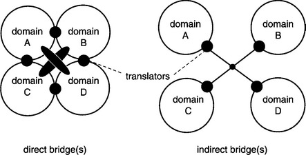
With a direct bridge, the behavior within a domain is translated directly into the behavior within the other domains. Therefore, for each pair of domains, a translator is needed that translates the behavior between the two domains. The direct bridge is characterized as follows:
![]() One translation operation between two domains
One translation operation between two domains
![]() The number of translators is squared to the number of domains
The number of translators is squared to the number of domains
Indirect bridges use a canonical intermediate format. Each domain has exactly one translator that transfers the behavior in the domain into an intermediate format and vice versa. This approach is characterized by the following:
The translators can be located at different levels. A distinction is made between
Translators at the ORB level are a part of the CORBA system and are usually provided by CORBA vendors, whereas translators at the application level are located outside the ORB and can be implemented by a user via DII, DSI, and interface repository. Because all calls in an application-level translator pass through DII and DSI, translators at the ORB level are considerably more efficient than those at the application level.
6.2 INTER-ORB PROTOCOLS
Based on the interoperability model described in Section 6.1, the CORBA specification defines data formats and protocols for constructing bridges between object domains. This provides interoperability support at two levels:
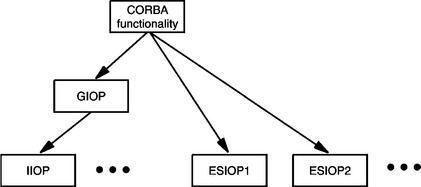
The General Inter-ORB Protocol (GIOP) is CORBAs native protocol to enable interoperability between CORBA ORBs. So-called Environment-Specific Inter-ORB Protocols (ESIOPs) also support interoperability between CORBA ORBs, but by tunneling CORBA requests over legacy protocols of other middleware systems.
GIOP is not bound to any particular transport protocol and therefore cannot be implemented directly; mappings from GIOP to transport protocols first have to be defined. For example, the Internet Inter-ORB Protocol (IIOP) defines a mapping from GIOP to TCP/IP.
GIOP and ESIOPs use a common architecture that enables objects to be referenced across domain boundaries. These are called Interoperable Object References (IORs). IORs, GIOP, and ESIOPs are dealt with in detail in the following sections. Figure 6.2 shows the relationship between GIOP, IIOP, and different ESIOP.
6.2.1 Interoperable Object References
An important characteristic that distinguishes domains is the way in which they represent object references. A common intermediate format is required for object references to guarantee interoperability across domain boundaries. The specification of this intermediate format (as well as the format for the representation of IDL data types) is actually the responsibility of a protocol such as GIOP. However, CORBA provides a general framework for the representation of object references that has to be mapped to the respective protocol used. The structure of IORs is oriented to the information required by a bridge:
IORs are specified through CORBA-IDL based on this information model. Through IDL the IORs are mapped automatically to specific protocols such as GIOP based on the rules for mapping IDL data types to a transfer syntax.
Due to the potential extensibility of the usable protocols and object services, the structure of much of the information contained in an IOR (such as addresses) was unknown at the time the IOR framework was designed. An IOR therefore consists of the object’s type identifier (type_id) and a set of profiles. Each profile contains all information that is necessary for access to the corresponding object through a particular access mechanism. If different mechanisms can be used to access an object, the IOR contains a profile for each mechanism. IORs without profiles represent a NIL object. A profile consists of a global identifier (tag) allocated by the OMG and unstructured data (profile_data). Each Inter-ORB protocol must specify the structure of this data.
The standard specifies a mechanism for converting IORs into character strings and vice versa to enable the easy transfer of IORs (for example, via email).
6.2.2 General Inter-ORB Protocol
Interoperability between different CORBA ORBs is based on the GIOP. Note that although a CORBA ORB is not required to provide GIOP in order to be compliant with the CORBA specfication, most CORBA products do in fact implement GIOP. This often cancels out the need for a bridge when ORBs of different vendors are working together.
GIOP was designed for use over different connection-oriented protocols (such as TCP) and consists of three components:
• Common Data Representation (CDR) defines a mapping of IDL data types to a byte stream.
• GIOP-message formats map ORB functionality (such as method invocations) to protocol messages.
• Protocol state machine defines sequences of possible messages exchanges (e.g., a reply message must be preceded by a request message).
The protocol messages themselves are specified by CORBA IDL and are also mapped through CDR to a byte stream that is to be transmitted. GIOP is abstract because it is not bound to any particular transport protocol. The specification merely contains some assumptions about the characteristics of usable transport protocols:
• Connection-oriented: The connection must be open before messages are transmitted and then closed afterwards.
• Reliable: Messages are not reordered and are only sent once.
• Byte-stream-oriented: There are no length restrictions for messages being transmitted and no packet boundaries.
• Failure notification: The user is informed in the case of failure.
Before GIOP can be used over a transport protocol that incorporates these characteristics, a definition of the mapping of GIOP to the respective protocol is required. IIOP is a mapping of GIOP to TCP/IP that each standard-compliant ORB must provide. Aside from IIOP, the CORBA standard does not currently define any other GIOP mappings. However, some products use special mappings. For example, the Realtime Inter-ORB Protocol (RIOP) used in TAO [32] is a mapping of GIOP to ATM. In addition to specifying the transport protocol to be used, each GIOP mapping defines the structure of the protocol profiles used in IORs (see Section 6.2.1). For example, an IIOP protocol profile contains the Internet address and the TCP port number of the communication end point where the object belonging to the IOR is located.
6.2.3 Environment-Specific Inter-ORB Protocols
While GIOP is CORBA’s native interoperability protocol between ORBs (also of different vendors), ESIOPs enable the interoperation of ORBs using existing legacy protocols of other middleware systems (e.g., DCE). ESIOPs therefore enable the intergration of other middleware platforms with CORBA at the protocol level. The provision of ESIOPs by CORBA vendors is optional.
Each ESIOP defines the mapping of IDL data types to the data types of the middleware being linked. The mapping of ORB functionality to the communication mechanisms of the other platform is also defined. Lastly each ESIOP specifies the format of the IOR protocol profiles.
The first ESIOP defined by the OMG was the DCE Common Inter-ORB Protocol (DCE-CIOP), introduced with CORBA 2.0. This protocol enables a simple integration of CORBA and OSF-DCE applications.
6.3 DESIGN OF MICO’S INTEROPERABILITY
As an extendible CORBA platform, MICO offers a general framework for the implementation of interoperability mechanisms. Based on this framework, we will present a design for the support of GIOP in MICO. Use of the framework not only enables the implementation of a certain GIOP mapping such as IIOP but also the provision of GIOP as a general mechanism.
6.3.1 Framework
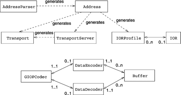
Along with some general tools, the interoperability framework provides mechanisms on the OSI model’s transport, presentation, and application layers. Most of these mechanisms are abstract in the sense that they are not linked to any particular protocol or data format. They are not linked to a concrete protocol or data format except through inheritance (derivation) from the framework classes and the implementation of additional methods. Figure 6.3 shows a UML diagram of the abstract components in the framework.
STORAGE MANAGEMENT
Efficient storage management is the key to an effective CORBA system. It is particularly important to avoid data copying as much as possible. The following is a list of some important locations where data potentially has to be copied:
• Between network hardware and interoperability modules
• Between interoperability modules and ORB kernel
• Between ORB kernel and object adapters
An important element of an interoperability framework is the ability to transform data items (e.g., an integer value) into a sequence of bytes that can be sent to a remote program as part of a network message. The process of converting a data item to such a byte sequence is commonly referred to as marshalling, and the reverse process of reconstructing a data item from a byte sequence is called demarshalling. The amount of storage space that will be required for data marshalling (i.e., the size of the resulting byte sequence) is often not known in advance. Therefore, in some cases data that has already been marshalled has to be copied into a larger storage area during marshalling.
The framework offers Buffer objects that manage contiguous storage areas, thereby limiting the amount of data that requires copying. These storage areas can be increased without copying through a close cooperation with dynamic storage management. Moreover, each Buffer has a reference counter. Thus the reference counter can simply be increased anywhere that stored data potentially has to be copied. If the Buffer is no longer required, the reference counter is decremented. If the reference counter reaches zero, the Buffer is deleted.
TRANSPORT LAYER
The framework offers suitable abstractions on the transport layer for connection-oriented transport protocols. Transport and TransportServer objects model the semantics of a connection-oriented protocol just as the GIOP expects. Just like GIOP, these objects are abstract in the sense that they are not linked to any specific protocol. Through inheritance these abstract objects can be bound to a specific protocol, such as TCP.
Transport objects model a communication end point using the following operations:
Invisibly to the user, the Transport objects work closely with the scheduler described in Section 5.3.4 to send and receive data. TransportServer objects model special communication end points that are used to set up new connections on the server side. If a remote Transport object sets up a connection to a TransportServer object, then the TransportServer object generates a new Transport object that can be used in exchanging data with the remote Transport object.
Address objects are used to address communication end points. They offer the following functions:
• Conversion of an address into a character string
• Conversion of a character string into an address
• Factory for Transport, TransportServer, and IORProfile objects
AddressParser objects are used for reconverting character strings into Address objects. A class derived from AddressParser must be provided for each address type.
Address objects are used as a factory [13] for creating Transport, Transport-Server, and IORProfile objects. (Note that IORProfile objects model the protocol profiles for the interoperable object references described in Section 6.2.1 and are provided by the framework as a mechanism for the application layer.)
For example, if an address exists in the form of a character string entered by the user, it can be converted into an Address object through the use of an AddressParser. Without the knowledge of which specific protocol the address belongs to, the Address object can create a Transport object that implements the protocol matching the address. Lastly, a connection can be established to the communication end point with this address and data exchanged without knowledge of which protocol was used.
Address and AddressParser objects are also abstract and must be linked to a particular protocol through inheritance.
PRESENTATION LAYER
The framework offers support on the presentation layer for marshalling and demarshalling IDL data types. DataEncoder objects convert IDL data types into a byte stream that is filed in a Buffer object. DataDecoder objects read a byte stream from the Buffer object and convert it into IDL data types. DataEncoder and DataDecoder objects are also abstract and have to be linked to a specific marshalling format such as CDR through inheritance.
APPLICATION LAYER
The application layer of the framework offers support in the creation and the decoding of the messages of an inter-ORB protocol, such as GIOP. Among other things, GIOPCodec objects provide operations for creating and decoding the following messages:
These messages are used to carry out method invocations (1, 2) and to cancel method invocations currently being processed (3). A DataEncoder object is used to generate a message that it then files as a byte stream in a Buffer object. When a message is received, the byte stream read from a Buffer object is decoded via an DataDecoder object.
Another component of the application layer consists of IOR objects that model the interoperable object references described in Section 6.2.1. Along with the type and the identification of a CORBA object, each IOR object contains a set of protocol profiles. The latter are modeled by IORProfile objects in the framework and have to be bound to a particular protocol through inheritance. At a minimum, protocol profiles contain the address where the corresponding CORBA object can be found. Consequently, Address objects can be used as a factory for creating the appropriate IORProfile objects.
6.3.2 GIOP
The abstract framework described in the preceding subsection enables GIOP to be implemented as an abstract mechanism independent of a particular transport protocol such as TCP. For a specific GIOP mapping such as IIOP, the corresponding abstract components of the framework have to be linked to concrete protocols through inheritance. For example, Table 6.1 lists the components used for IIOP.
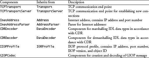
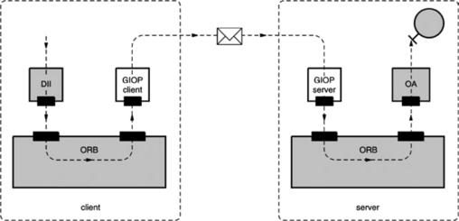
Figure 6.4 shows how the two components GIOP client and GIOP server support GIOP in MICO. From the view of the ORB, the GIOP client is an invocation-executing component that—like an object adapter—accepts method invocations from the ORB but then converts them into GIOP messages and sends them to a GIOP server. The GIOP server is an invocation-generating component that receives messages, converts them into method invocations, and then sends them to the local ORB. The two subsections that follow take a closer look at the structure of GIOP clients and servers.
GIOP CLIENT
Figure 6.5 shows how components of the framework are used to implement the GIOP client. A GIOPCodec converts a method invocation arriving from the ORB (request in Figure 6.5) into a protocol message and files it as a byte stream in a Buffer. The GIOPCodec uses a suitable DataEncoder to marshal the data types. Connections to GIOP servers are represented in the client by Transport objects. For reasons of efficiency, a connection to a GIOP server exists beyond the duration of a method invocation so that later method invocations to the same GIOP server can use the same connection. Consequently, the GIOP client uses a table to keep a record of existing connections and the addresses of the corresponding servers. When it sends a message, the GIOP client extracts the address of the appropriate GIOP server from the object reference of the target object of the method invocation and consults its table. If the address is not listed in the table, it sets up a new connection and enters it into the table. The message is then sent via the Transport object.
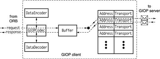
The results of the method invocation are filed in a Buffer and decoded by the GIOPCodec with the help of a DataDecoder. The result (response in Figure 6.5) is made known to the ORB.
GIOP SERVER
The GIOP server is the counterpart of the GIOP client. It also has to use a table to keep a record of the connections that exist to the GIOP client. If a GIOP client wants to send a message to a GIOP server, it first has to establish a connection to the server. As shown in Figure 6.6, it sends a connection request to the server that arrives at the TransportServer object in the GIOP server (connect in Figure 6.6). A Transport object for the new connection is then created in the server and entered into the connection table. The GIOP client is now able to exchange messages with the GIOP server.

If a message arrives at the server, it is decoded by the GIOPCodec using a DataDecoder. The resulting method invocation (request in Figure 6.6) is sent to the ORB for execution. If the ORB later notifies the GIOP server of the result of the method invocation (response in Figure 6.6), the GIOPCodec then uses DataEncoder to marshal the result into a Buffer. Lastly, the server consults its connection table to find the Transport object over which the message is to be sent to the GIOP client. In contrast to the client, the GIOP server can assume that a corresponding entry already exists in the table, since the client had already opened the connection to receive the method invocation message.
6.4 SUMMARY, EVALUATION, AND ALTERNATIVES
The construction of interoperability components is supported in MICO by an abstract framework that is not bound to any particular protocol. On the basis of this framework, GIOP in MICO can be implemented without being bound to specific transport protocols such as TCP. For the support of certain GIOP mappings such as IIOP, the abstract components of the framework merely have to be linked to concrete protocols through inheritance.
GIOP support is implemented through two services outside the microkernel ORB presented in Chapter 5: the GIOP client transforms the method invocations received from the ORB into network packets; the GIOP server receives these network packets and converts them into method invocations on the ORB. This approach is characterized as follows:
![]() Simple integration of new GIOP mappings
Simple integration of new GIOP mappings
![]() Simple integration of new inter-ORB protocols (e.g., ESIOPs)
Simple integration of new inter-ORB protocols (e.g., ESIOPs)
The additional overhead means that a lookup is required in the connection table for each method invocation. With a conventional ORB implementation in which the interoperability modules are part of the ORB, the allocation to the Transport objects can be stored directly in stub objects. In this case, no table and consequently no lookup are required. If suitable data structures are used (for example, hash tables), the disadvantage is negligible in practice.