
IDL COMPILER
The Interface Definition Language (IDL) of CORBA represents a powerful tool for the development of distributed applications. It enables a separation of the interface and the implementation of objects. The CORBA standard contains a description of the syntax and the semantics of the IDL. Applications programmers use IDL compilers to generate type-safe access to CORBA objects from interface specifications. This chapter is devoted to the design of MICO’s IDL compiler. The proxy objects generated by IDL are based on an ORB API that is described in Section 9.1. Section 9.2 follows with general principles relating to compiler construction. Sections 9.3 and 9.4 offer a detailed presentation of the design of MICO’s IDL compiler.
9.1 INVOCATION ADAPTERS
One of the tasks of an ORB consists of preparing and processing remote operation invocations. The initiator and the receiver of such operation invocations is an application based on CORBA. To execute an operation invocation, an application requires an invocation adapter, which is also used for the proxy objects generated by the IDL compiler. The invocation adapter allows the delivery of information associated with a remote operation invocation. This includes information about the target object, the operation name, and the actual parameters. This section focuses on the different alternatives for the design of invocation adapters.
9.1.1 Dynamic versus Static Invocation Adapters
An application uses an invocation adapter to send operation invocations (also see Section 5.3.1). The Dynamic Invocation Interface (DII) is an example of an invocation adapter. The DII defines an API with which operations including their parameters can be built at runtime and transferred to the ORB for further processing. Since the interfaces, which are based on the DII, do not have to be known at the compile time of an application, they are an example of a dynamic invocation adapter.
The specification of object interfaces is an important step in the design of an application. The interfaces are therefore already established at the time of the compilation of an application. With its IDL the CORBA specification offers a tool for the specification of such interfaces. A static invocation adapter converts object interfaces that are already known at the time of translation of an application.
Static invocation adapters incorporate the following benefits and disadvantages:
![]() Documented interface is part of the design of an application.
Documented interface is part of the design of an application.
![]() Allows type-safe handling of objects; errors are often detected before translation.
Allows type-safe handling of objects; errors are often detected before translation.
In contrast, dynamic invocation adapters incorporate the following benefits and disadvantages:
9.1.2 Support of Static Invocation Adapters
Proxy objects that guarantee type-safe access to object interfaces are a component of static invocation adapters. The proxy objects, which include stubs and skeletons, are derived from IDL specifications. Because proxy objects are linked to an application, they must exist in the same programming language as the application. Consequently, standard IDL language mappings are specified in CORBA for different programming languages.
According to the CORBA standard, a compliant ORB implementation must support an IDL language mapping for at least one programming language. The mapping is supported by a tool that can be implemented in various ways. For example, a C++ compiler could be extended to support the IDL directly. However, this would imply a close coupling between C++ compilers and special ORB implementations, which is not practical in reality.
Another approach can be taken to avoid the close coupling. A special tool translates IDL specifications into stubs and skeletons as the source code for a higher programming language taking into account the IDL language mapping rules. This source code must be compiled and linked with the rest of the application. Because of its task, this tool is called an IDL compiler. A CORBA application therefore consists of several components that exist in a specific dependency relationship to one another.
ORB library: The ORB library contains CORBA-specific functions that are required by all CORBA applications (such as implementation of the IIOP protocol).
Proxies: The proxy objects that the stubs and skeletons belong to are generated automatically by an IDL compiler from IDL specifications.
Application: The semantics of the actual application that is contributed by the programmer.
Figure 9.1 shows the dependencies between the three components in the form of layering. The ORB library provides the basic functionality of a CORBA application and is self-sufficient in terms of the other two components. The proxies have recourse to the functionality of the ORB library. For their part the proxies offer applications type-safe access to CORBA objects. The application itself uses the proxies as well as the functionality of the underlying ORB library.
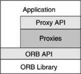
FIGURE 9.1 CORBA application consisting of the application itself, the generated code, and the ORB library.
Different interfaces exist between the three layers:
• ORB library ↔ Application: The application can access ORB-specific functions. These include initialization of the ORB or general functions for the management of object references.
• Application ↔ Proxies: The proxies generated from an IDL specification are used by an application for type-safe access to remote objects.
• Proxies ↔ ORB library: Proxies for their part need the support of the ORB to convert the parameters of a remote operation invocation into a byte sequence, for example.
Two of the three interfaces between the layers are prescribed by the CORBA standard and therefore offer no freedom for design decisions. However, the CORBA standard makes no statements about the interface between the proxies and the ORB library. From the standpoint of its functionality, this interface must provide support for remote operation invocations. This task corresponds to that of the dynamic invocation adapter already discussed. So it is possible that the proxies access the DII and the DSI. The advantage of such a procedure is that it makes maximum use of the components of the ORB, and this is what earlier versions of MICO did. However, the DII and the DSI are not runtime efficient, which indicates a weakness in the CORBA standard. Later versions of MICO therefore use the MICO-specific interface that is described in the following subsection.
9.1.3 MICO’s Static Invocation Adapter
Figure 9.2 shows the class diagram for the static invocation adapter under MICO. Functionally, the static invocation adapter is identical to the DII and the DSI. However, this is a MICO-specific interface that should never be used directly by applications to guarantee portability. Unlike the DII and the DSI, the static invocation adapter avoids the process of copying parameters as much as possible because of its focus on increasing runtime efficiency.
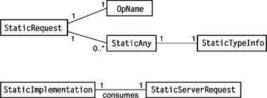
The class StaticAny is the counterpart of the static invocation adapter to the type Any defined in CORBA, which is used as a generic data container. An instance of the class StaticAny manages a typed data instance. Access to a StaticAny is via the class StaticTypeInfo. The class StaticTypeInfo takes on the role of a marshaller, which packs and unpacks user-defined data into and from a StaticAny instance. The class StaticTypeInfo is abstract. A class that can marshall the instances of this type must be derived for each user-defined type in an IDL specification. The following code fragment shows an extract from the declaration for the class StaticTypeInfo:
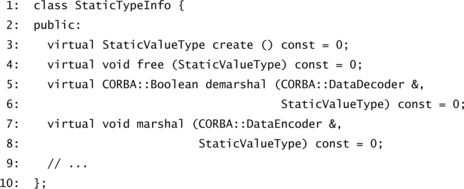
Along with other declarations, pure virtual methods for the storage management of data (lines 3 and 4) as well as the packing and unpacking of data (lines 5 and 7) are found in the abstract class StaticTypeInfo. An instance of the type StaticValueType represents a raw byte sequence managed by the class StaticAny together with the type information. The IDL data marshallers DataDecoder and DataEncoder are used to pack or unpack these byte sequences.
The class StaticRequest allows the client access to the functionality of the static invocation adapter. An instance of this class represents an operation invocation and manages all information associated with the operation invocation, including the operation name and the list of actual parameters. The class Sta-ticServerRequest reflects the same behavior on the server side. An incoming operation invocation is delivered to the object implementation through the class StaticImplementation at the server. The skeleton generated by the IDL compiler is derived from this class. An instance of the class StaticServerRequest is passed to the class StaticImplementation for each incoming operation invocation. Table 9.1 summarizes the individual classes of static invocation adapter.
TABLE 9.1
Classes of static invocation adapters
| Class | Description |
| StaticAny | Manages a datum and its type information |
| StaticTypeInfo | Defines interface for marshaller |
| StaticRequest | Encapsulates client-side information of an operation invocation |
| StaticServerRequest | Encapsulates server-side information of an operation invocation |
| StaticImplementation | Base class of the implementation of an interface hierarchy |
9.2 COMPILER FUNDAMENTALS
The task of a compiler is to translate a word of the language L1 into a word of the language L2 (see Figure 9.3). Compilers are typically used for the translation of higher programming languages such as C++, Fortran, and Pascal to assembly language. In the context of CORBA, the compiler translates IDL specifications into proxy objects. The source language is IDL, and the target language is a higher programming language—in our case, C++. The IDL compiler has to obey the IDL language-mapping rules for C++ at the time of translation. Before we look at IDL compilers in detail, we first want to start with a brief overview of the fundamentals of compiler construction.
9.2.1 Formal Languages and Grammars
The concept of formal language is central to the understanding of compilers. A formal language is based on an alphabet from which words are formed. For example, the alphabet Σ = {a, b} enables the forming of words such as a, aa, ab, and abba. The set of all words that can be created from an alphabet is represented by Σ+. In addition to all words from Σ+, the set Σ* also contains the empty word ε.
Based on the alphabet Σ, the language L is a subset of all words: L ⊆ Σ*. If Σ = {a, b}, then a possible language LP is the one of the palindrome, that is, words that are the same read forwards and backwards. Some valid words in this language are LP = {a, bb, bab, abba,…}.
First we will look at how a language is represented by a finite description. This requires the helper alphabet N, which is also called a set of nonterminal symbols. The name originates from the fact that the symbols of the alphabet do not appear in the words of a language. Therefore, N ∩ Σ = ∅![]() . In the discussion below, nonterminal symbols are characterized by capital letters: N = {Q, R, S, …}.
. In the discussion below, nonterminal symbols are characterized by capital letters: N = {Q, R, S, …}.
A production is the mapping of a nonterminal symbol to a word that consists of a union of the alphabets Σ and N. For the production u → v, the symbols u ε N and v ε(Σ ∪ N)* are valid. The set of all productions is defined by P = {u → v|u ε N, v ε(Σ ∪ N)*}. For example, if Σ = {a, b} and N = {S, R}, then R → a, R → bS, S → aSa, and S → a Sa R are possible productions.
A derivation is the transformation of a word into another one according to a production. If w, w′ ε (Σ ∪ N)* are two words, the derivation is w ⇒ w’ if when the production is ν → v ε P, so that w′ derives from w, whereby all occurrences of u in w are replaced by ν. For example, bSb ⇒ baSab with the productions of the last paragraph because baSab is derived from bSb when the production S → aSa is used to exchange the S in bSb with aSa. A derivation sequence w0 ⇒ w1 ⇒ … ⇒ wn is abbreviated as ![]() .
.
A grammar G is a quadruple G = (Σ, N, P, S) with the alphabet Σ, the nonterminal symbol N, a set of productions P, and a start symbol S ε N. A grammar is a finite representation of a formal language. The language L(G) induced by the grammar G is defined as ![]() . This means L(G) contains all words resulting from a finite derivation sequence from the start symbol S of the grammar G. For example, the grammar GP = (ΣP, NP, PP, S) creates the language of the palindrome, with L(GP) = LP. ΣP = {a, b}, N = {S} and the set of the productions PP:
. This means L(G) contains all words resulting from a finite derivation sequence from the start symbol S of the grammar G. For example, the grammar GP = (ΣP, NP, PP, S) creates the language of the palindrome, with L(GP) = LP. ΣP = {a, b}, N = {S} and the set of the productions PP:
The word abba ε L(GP) derives, for example, from the following derivation string: S ⇒ aSa ⇒ abSba ⇒ abba. The first derivation uses production 9.4; the second one, production 9.5; and the third one, production 9.1 from PP.
9.2.2 Parse Trees
An analogous graphic representation exists for the derivations presented in the last subsection. This structure is called a parse tree and is a tree in the mathematical sense: its inner nodes consist of nonterminal symbols and its leaves consist of words of the alphabet. Figure 9.4 shows the parse tree for the derivation S ⇒ aSa ⇒ abSba ⇒ abba based on the grammar GP presented in the last section.

The use of a production is represented in the parse tree by an inner node. The node corresponds to the left side of the production and its successor node to the right side of the production. The children of a node therefore represent the substitutions undertaken during a derivation. A traversing of the parse tree in in-order traversal visits the terminal symbols (i.e., leaves) in the sequence in which they appear from left to right in the word.
One of the tasks of a compiler is to find a suitable derivation, which is the generation of a parse tree. Tools are available that take the description of a grammar to generate programs that create parse trees from input words. The CORBA standard specifies the IDL through a grammar so that when these tools are used the conversion of an IDL specification (i.e., word of the input language) into a parse tree is for the most part automated.
9.2.3 Structure of a Compiler
The creation of a parse tree is the first step in the translation of one language into another one. It normally makes sense to translate a language into more than one target language instead of only into one. In the context of an IDL compiler, for example, there are various target languages for which CORBA has specified IDL language mappings. This requires breaking down the translation process for the generation of a parse tree and the subsequent code generation into the target language. The parse tree is used as a link that separates the two phases of the translation.
As we illustrated in the preceding subsection, the structure of the parse tree is oriented toward the productions of the grammar of the input language. If this grammar contains numerous productions, as is the rule with complicated languages, the parse tree will become fairly complex. Therefore, it is useful first to convert the parse tree into a more compact representation. The more compact form, also called the abstract syntax tree (AST), serves as the starting point for code generation.
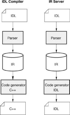
The phases passed through by the translation process are called parsing and code generation (see Figure 9.5). The task of a parser consists of converting a word from the source language into an abstract syntax tree. The syntax and the semantics are checked during this process. Only correct input words (in our context this means correct IDL specifications) are represented as abstract syntax trees. The components of a compiler that implement the first phase of the translation process are referred to as the front end in the literature.
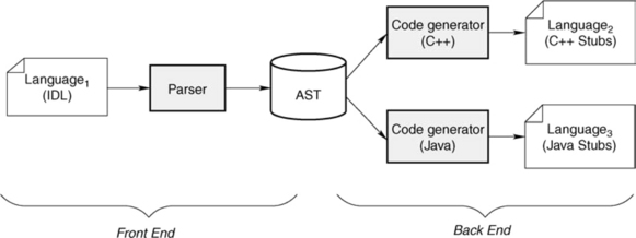
The second phase of the translation process is code generation. The components of a compiler that have this responsibility are accordingly referred to as the back end. The back end traverses the abstract syntax tree that was constructed beforehand by the front end and produces code in the target language. The back end implements the rules of IDL language mapping for the target language and generates the necessary proxy objects. Figure 9.5 shows two different back ends that are creating these proxy objects in both the programming languages C++ and Java.
9.3 ABSTRACT SYNTAX TREE FOR IDL SPECIFICATIONS
An abstract syntax tree is the link between the front end and the back end. In the context of IDL compilers, there is the issue of the structure of the abstract syntax tree for IDL specifications. The abstract syntax tree of an IDL specification must be able to represent all information necessary for the back end, including the IDL specification itself as well as information about file structures in which the IDL specification is filed. For example, the latter is important in order to establish in which file each part of the IDL specification is defined (such as through the use of the preprocessor instruction #include).
For the purposes of object-oriented modeling, a separate class can be introduced for each IDL construct (for example, typedef, struct, interface,…) in order to represent the complex information contained in an IDL specification. Each class then manages information that exists for this IDL construct. For example, the class that represents interface definitions would contain a list of nested objects that represent the IDL constructs defined locally in an interface.
A closer examination reveals that a similar modeling already exists in the CORBA standard. The interface for the interface repository (IR) mirrors the language constructs contained in the IDL exactly. The actual task of the IR is to store IDL specifications. Therefore, it is possible for an IR to be used as an abstract syntax tree for an IDL compiler. The resulting design of the IDL compiler uses the IR as a link between front end and back end: The front end writes an IDL specification into the IR, and the back end extracts the information from the IR during code generation (see left half of Figure 9.6).
This sort of design is also advantageous for the implementation of the IR itself. The IR can use the IDL compiler to implement persistence of the IDL specifications contained in the IR. When the IR is started, the front end of the IDL compiler is used to load the persistent state of the IR. During the termination of the IR, the back end of the IDL compiler can be used to back up the actual state (see right half of Figure 9.6). The back end needed to do this generates code based on the IDL syntax. The persistent state then exists in the form of a readable IDL specification. The advantage of the close coupling between IDL compiler and IR is the reusability of the components required for their conversion.
Another benefit of this design is that different configurations are possible. Because the abstract syntax tree is represented by an IR, the IDL compiler can access a remote IR. Because the IR is a regular CORBA object, it can be reached with normal remote operation invocations. This also applies to IRs of other ORB vendors, so long as the implementation conforms to the CORBA standard. The IDL compiler can therefore “feed” a remote IR (using the front end) as well as implement code generation in the back end using the information of a remote IR.
These advantages are also offset by some disadvantages. One disadvantage is the result of a peculiarity of the CORBA IDL that allows the reopening of module specifications. The following IDL specification is used to elucidate this point:
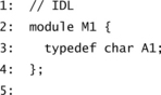
The above specifications contain two modules: module M1 contains two definitions and module M2 contains one definition. What is special about this is that the definitions produce cyclical dependencies between the two modules. Module M1 contains definitions that are based on definitions from module M2 and vice versa. If an IR is used as an abstract syntax tree for representing an IDL specification, modules M1 and M2 are both represented by an object within the IR.
If during code generation the back end passes through the content of the IR sequentially this would produce the following sequence of IDL definitions: M1::A1, M1::A3, M2::A2 (first all definitions from module M1 and then from module M2). However, this sequence is not correct because the definition from M1::A3 is based on M2::A2 and therefore should occur later. The more serious problem here is that some of the information contained in the IDL specification is lost in the IR. This includes the sequence in which IDL specifications occur in a specification and the mapping of IDL definitions to source files in which they are defined. We will deal with these problems later.
Another disadvantage of using an IR as a link between the front end and the back end of an IDL compiler is the conversion of this design during implementation. The CORBA standard defines the interface of the IR through an IDL specification. This means that the front and back ends of the IDL compiler access the IR over a CORBA interface. A typical “chicken-and-egg” problem occurs during the development of the IDL compiler and the IR: An implementation of the IDL compiler requires the availability of an IR and vice versa. The reason is that, as a regular CORBA object, the IR requires proxies, but these first have to be created by a working IDL compiler.
This problem can be solved through a bootstrap procedure: The required stubs and skeletons for the IR are first developed manually and later replaced by ones generated by the IDL compiler as soon as the compiler has sufficient functionality. The result is that automatically generated code, produced during the bootstrap procedure, is also contained in the MICO source code. Because the generated code is part of the MICO source code, this also means that the code generated by the IDL compiler must be translatable with all supported C++ compilers.
In summary, the use of an IR to represent an abstract syntax tree produces the following advantages and disadvantages:
![]() Simple design; interfaces specified by CORBA
Simple design; interfaces specified by CORBA
![]() Reuse of components of the CORBA architecture
Reuse of components of the CORBA architecture
![]() Support for basic persistence of the IR
Support for basic persistence of the IR
![]() Code generation from a remote IR possible
Code generation from a remote IR possible
![]() Persistence of IR not scalable or failsafe
Persistence of IR not scalable or failsafe
![]() Some information from IDL specifications not representable in the IR
Some information from IDL specifications not representable in the IR
![]() Bootstrap procedure required during development of IDL compiler
Bootstrap procedure required during development of IDL compiler
9.4 MICO’S IDL COMPILER
The following sections examine the design of MICO’s IDL compiler. We start by looking at the general class structure of an IDL compiler in Section 9.4.1. A more detailed discussion about the structure of the front end follows in Section 9.4.2 and about the C++ back end in Section 9.4.3.
9.4.1 Class Structure
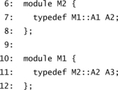
Figure 9.7 shows the complete class structure of an IDL compiler in the UML-based notation. Brief descriptions of the individual classes in Figure 9.7 are found in Table 9.2.
TABLE 9.2
Classes of IDL compiler and their function
| Class | Description |
| CodeGen | Abstract base class for all back ends |
| CodeGenCPP | Code generation for C++ |
| CodeGenIDL | Code generation for IDL |
| IDLDep | Computes dependencies between IDL definitions |
| IDLError | Output of detailed error messages |
| IDLParam | Command line parameters of IDL compiler |
| IDLParser | Traverses parse tree and fills IR |
| IR | Interface repository |
| Output | Supports structured output |
| ParseNode | Parse tree |
| Parser | Encapsulates parser generated by YACC |
The arrangement of the classes among themselves reflects the division into the front end and the back end of the IDL compiler linked together over an abstract syntax tree (based on the IR). The class IR forms the separation between the front and back ends. The classes Parser, ParseNode, and IDLParser represent the front end, and the other classes the back end.
In Figure 9.7 the IR is only represented by one class, but in reality it is based on a set of classes. The design of the IR will not be discussed further. The CORBA standard already suggests a design through its abstractions for the interface of the IR. The implementation of the IR in MICO relies closely on the interface structure defined by the CORBA standard.
In Section 9.3 we explained that the IR is not able to store all information that exists in an IDL specification. For example, it is not possible from the IDL definitions contained in an IR to extract the source code file from which they originated. This could be seen as a weakness in the CORBA specification. On the other hand, the standard does not make it mandatory for the IR to be used for the IDL compiler. In Section 9.3 we also explained that the sequence of IDL definitions, as they occur in a source code file, is lost in an IR. The back end has a class IDLDep (standing for dependency) that computes the correct sequence for the code generation. This information can be calculated by IDLDep based on the dependencies between IDL definitions contained in the IR.
9.4.2 Front End
The task of the front end is to input source code files that contain IDL specifications and to store their content in an IR. The CORBA standard defines the syntax of the IDL through a grammar. As already explained in Section 9.2.2, tools are available that automatically generate parsers from grammars. The output of a parser is a parse tree, the information of which is filed in a compact form in an IR.
MICO uses the parser generator YACC (Yet Another Compiler Compiler). The class Parser in Figure 9.7 encapsulates the code generated by YACC. The parser converts input streams with valid IDL specifications into parse trees. A parse tree is represented by a set of instances of the class ParseNode. The tree that is created is processed by the class IDLParser and stored in a compact form in the IR.
The class Parser checks the syntax of an IDL specification, whereas the class IDLParser tests the semantics of the input. This includes the reference to a user-defined IDL type that was not defined before its use. If such an error occurs, the class IDLError is used to give an informative error message. If the input is error free, the first phase of the translation of an IDL specification is completed when the IR contains the complete specification.
The following example clarifies the front-end procedure. The IDL specifications that appear serve as the input of the IDL compiler.
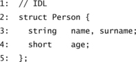
The IDL specification is syntactically and semantically correct and defines a user-specific data type Person. The following extract from a CORBA specification shows the part of the IDL grammar that provides the syntax of the above IDL specification:
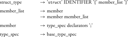
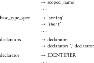
The parser generator YACC is used to generate a parser from the grammar. Using the above IDL specification as input, the parser generated by the YACC creates the parse tree shown in Figure 9.8. Each node in the parse tree in Figure 9.8 corresponds to an instance of the class ParseNode. Once the parse tree is constructed (and consequently the input recognized as syntactically correct), the class IDLParser collects the information contained in the parser tree and represents it as an object within the IR. This object is created with the name create_struct() through an operation of the IR. The input parameters of cre-ate_struct() correspond to the information contained in the parse tree.
9.4.3 Back End
The back end is responsible for code generation. Different back ends can generate code for different target languages. For example, Figure 9.5 shows this with C++ and Java. The back end is selected on the basis of command line parameters to the IDL compiler. The back end converts the IDL language-mapping rules for a particular language. It derives the input from the content of the IR. This section focuses on the back end for the language C++.
In C++ a distinction is made between two types of program elements: declarations and definitions. A declaration makes the definition of a program construct known to the C++ compiler without stipulating its implementation. In contrast, a definition indicates the implementation of a program construct. A declaration is more abstract than a definition in the sense that it provides a specification, whereas a definition provides an implementation.
This distinction is necessary if an application is being divided into several translation units. The dependencies between the translation units are resolved through the use of declarations. Dependencies arise, for example, between an application and the proxy objects. The application requires the declarations of the stubs and the skeletons in order to use the proxy objects. If an entire application is linked to an executable program file, the definitions of the proxies also have to be included.
Per convention, declarations and definitions are normally stored in different files. All declarations end up in a header file that is typically assigned the file name suffix .h. The definitions are found in an implementation file. Here different C++ compilers use different suffixes for the file names. The most common ones are .cc, .cpp, and .cxx. MICO’s IDL compiler generates two files for C++ language mapping from one IDL specification—one each for the declarations and the definitions.
Figure 9.9 shows the design of the back end for the generation of C++ stubs and skeletons. Each back end is derived from the class CodeGen, which defines the interface to a back end. The individual rules of IDL language mapping for C++ are accommodated in different classes. Table 9.3 offers an overview of the different classes of a C++ back end, along with their functionality.
TABLE 9.3
Classes of C++ back end and their function
| Class | Description |
| CPPTypeFolder | Eliminates identical C++ types |
| CodeGen | Abstract base class for all back ends |
| CodeGenCPP | Code generation for C++ |
| CodeGenCPPCommon | Generates code for all declarations |
| CodeGenCPPSkel | Generates definitions belonging to skeleton |
| CodeGenCPPStub | Generates definitions belonging to stub |
| CodeGenCPPUtil | General methods |
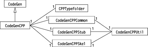
The class CPPTypeFolder merits special mention. Different IDL types that are all mapped to the same C++ type can occur in an IDL specification. For example, the two IDL types string<3> and string<8> (each representing length-bounded strings) are mapped to the C++ type char*. Because double definitions should be avoided in generated C++ code (they would cause an error when the generated C++ code is translated), the class CPPTypeFolder is responsible for removing duplicates.
This section has not described the structure of the generated code. The code generated by MICO’s IDL compiler is based on MICO’s specific static invocation adapter and therefore is not portable (and this is not something required by the CORBA standard). Section C.5 in Appendix C presents the internal implementation details of generated code for an IDL specification.
9.5 SUMMARY, EVALUATION, AND ALTERNATIVES
An IDL compiler translates an IDL specification into the proxy objects of a specific higher programming language. A compliant CORBA implementation must support at least one IDL language mapping. In MICO this requirement is met by providing an IDL compiler. The front end reads an IDL specification, carries out syntactical and semantic checks of the specification, and then stores it in an interface repository. In MICO the IR serves as a representation of the abstract syntax tree. The back end traverses the content of the IR and generates stubs and skeletons in the programming language C++.
There are some advantages associated with using the IR to represent the abstract syntax tree. An IR must exist for every compliant implementation of the CORBA standard anyway and can therefore be reused for building an IDL compiler. The disadvantage is that some of the information needed for code generation cannot be represented in an IR and therefore must be passed to the back end in different ways.
Whereas the interface between the proxy objects to be used by the IDL language mapping is defined in the CORBA specification, an ORB developer has the freedom to select how these proxies are implemented and on which ORB API they are based. From the standpoint of reusability it would also be possible to use the DII and the DSI of the ORB API. These components are just as necessary for a compliant CORBA implementation as the IR is. This is also how earlier versions of MICO were structured. Due to deficiencies in the DII and the DSI in terms of runtime efficiency the static invocation adapter in MICO introduced an ORB API specifically for proxies.
It is not necessarily the case that an IDL compiler is the only way that the requirement of IDL language mapping for compliant CORBA implementations can be met. With C++, IDL compilers are effective for supporting the language mapping. For programming languages that offer reflexive mechanisms, other solutions are conceivable. A reflexive language allows introspection at runtime; that is, a program based on a reflexive language is able to obtain information about itself. Therefore, generic proxy objects could be developed as part of the ORB library. The generic stub and skeleton would then use the reflexive characteristics of the language to provide the signature of an operation at runtime, for example. An IDL compiler is therefore not necessary in this case. A programming language that enables this approach is Smalltalk.