
Chapter 3. Building Connectivity
Refer to the following sections for information about these topics:
• 3-1: Configuring Interfaces—Discusses how you can configure firewall interfaces to join and communicate on a network. Physical, trunk, and logical interfaces are covered, as well as priority queue operation.
• 3-2: Configuring Routing—Explains the configuration steps needed to define static routes on a firewall, as well as the RIP, OSPF, and EIGRP dynamic routing protocols.
• 3-3: DHCP Server Functions—Provides information about how a firewall can operate as a DHCP server and a DHCP client. These functions support dynamic addressing for the firewall and for internal hosts, without the use of a dedicated DHCP server.
• 3-4: Multicast Support—Presents the configuration steps needed to allow a firewall to forward multicast traffic in a secure manner and to participate in multicast routing.
A firewall must be configured with enough information to begin accepting and forwarding traffic before it can begin doing its job of securing networks. Each of its interfaces must be configured to interoperate with other network equipment and to participate in the Internet Protocol (IP) suite.
A firewall must also know how to reach other subnets and networks located outside its immediate surroundings. You can configure a firewall to use static routing information or information exchanged dynamically with other routers. You can even configure a firewall to handle IP multicast traffic, either as a proxy or as a multicast router.
You can also configure a firewall to provide various Dynamic Host Control Protocol (DHCP) services so that hosts connected to its interfaces can get their IP addresses dynamically.
This chapter discusses each of these topics in detail.
3-1 Configuring Interfaces
Every firewall has one or more interfaces that can be used to connect to a network. To pass and inspect traffic, each firewall interface must be configured with the following attributes:
• Name.
• IP address and subnet mask (IPv4; beginning with Adaptive Security Appliance (ASA) 7.0 and Firewall Services Module (FWSM) 3.1(1), IPv6 is also supported).
• Security level (a higher level is considered more secure).
By default, traffic is allowed to flow from a higher-security interface to a lower-security interface (“inside” to “outside,” for example) as soon as access list, stateful inspection, and address translation requirements are met. Traffic from a lower-security interface to a higher one must pass additional inspection and filtering checks.
Firewall interfaces can be physical, where actual network media cables connect, or logical, where the interface exists internally to the firewall and is passed to a physical trunk link. Each Cisco firewall platform supports a maximum number of physical and logical interfaces. Starting with PIX OS release 6.3, trunk links are also supported. The trunk itself is a physical interface, and the Virtual LANs (VLAN) carried over the trunk are logical VLAN interfaces. A trunk link has the following attributes:
• Firewall trunk links support only the IEEE 802.1Q trunk encapsulation method.
• As each packet is sent to a trunk link, it is tagged with its source VLAN number. As packets are removed from the trunk, the tag is examined and removed so that the packets can be forwarded to their appropriate VLANs.
• 802.1Q trunks support a native VLAN associated with the trunk link. Packets from the native VLAN are sent across the trunk untagged.
• A firewall does not negotiate trunk status or encapsulation with Dynamic Trunking Protocol (DTP); the trunk is either “on” or “off.”
Figure 3-1 shows how a trunk link between a firewall and a switch can encapsulate or carry frames from multiple VLANs. Notice that frames from the native VLAN are sent without a tag, and frames from other VLANs have a tag added while in the trunk.
Figure 3-1 How an IEEE 802.1Q Trunk Works on a Firewall
Surveying Firewall Interfaces
You can see a list of the physical firewall interfaces that are available by using the following command:
Firewall# show version
Firewall interfaces are referenced by their hardware index and their physical interface names. For example, the show version command on a PIX 525 running PIX release 6.3 produces the following output:
Firewall# show version
0: ethernet0: address is 0030.8587.546e, irq 10
1: ethernet1: address is 0030.8587.546f, irq 11
2: gb-ethernet0: address is 0003.4725.2f97, irq 5
3: gb-ethernet1: address is 0003.4725.2e32, irq 11
The first number is the hardware index, which indicates the order in which the interfaces were placed in the firewall backplane. Each physical interface has a hardware ID name that indicates its medium; ethernet0 is a 10/100BASE-TX port, and gb-ethernet0 is a Gigabit Ethernet port.
With ASA 7.0 and later, the output is slightly different:
Firewall# show version
0: Ext: Ethernet0 : media index 0: irq 10
1: Ext: Ethernet1 : media index 1: irq 11
2: Ext: GigabitEthernet0 : media index 0: irq 5
3: Ext: GigabitEthernet1 : media index 1: irq 11
Tip
On an FWSM, all interfaces are logical and have names beginning with vlan followed by the VLAN number. With a default configuration, the only VLAN interfaces available are the ones that have been configured from the Catalyst switch Supervisor module. These are created with the following Catalyst IOS configuration commands:
Switch(config)# firewall vlan-group group vlan-list
Switch(config)# firewall module mod vlan-group group
In the first command, an arbitrary VLAN group number, group, is defined to contain a list of one or more VLANs that will be internally connected to the FWSM. The second command associates the FWSM located in switch chassis slot mod with the VLAN group vlan-group. For example, the following commands can be used to provide VLANs 10, 20, and 30 to the FWSM located in slot 4:
Switch(config)# firewall vlan-group 1 10,20,30
Switch(config)# firewall module 4 vlan-group 1
Logical interfaces have a hardware ID in the form vlan1, vlan55, and so on. These interfaces are not available until you define them with configuration commands, so they are not shown in the show version output.
At this point, you should identify each of the interfaces you will use. At a minimum, you need one interface as the “inside” of the firewall and one as the “outside.” By default, the firewall chooses two interfaces for the inside and outside. You can view the interface mappings with the show nameif EXEC command. You also can change the interface-name mappings as needed.
Tip
The show interface command lists each interface along with its state, MAC and IP addresses, and many counters. You can use the output to verify an interface’s activityand current settings.
The interface state is shown by two values: The configured administrative state (up or administratively down) and the line protocol state (up or down). The line protocol state indicates whether the interface is connected to a live network device.
Configuring Interface Redundancy
By default, each physical firewall interface operates independently of any other interface. The interface can be in one of two operating states: up or down. When an interface is down for some reason, the firewall cannot send or receive any data through it. The switch port where a firewall interface connects might fail, causing the interface to go down, too.
Naturally, you might want to find a way to keep a firewall interface up and active all the time. Beginning with ASA 7.3(1), you can configure physical firewall interfaces as redundant pairs.
As a redundant pair, two interfaces are set aside for the same firewall function (inside, outside, and so on) and connect to the same network. Only one of the interfaces is active; the other interface stays in a standby state. As soon as the active interface loses its link status and goes down, the standby interface becomes active and takes over passing traffic.
Both physical interfaces in a redundant pair are configured as members of a single logical “redundant” interface. In order to join two interfaces as a redundant pair, the interfaces must be of the same type (10, 100, 1000BASE-TX GigabitEthernet, for example).
The redundant interface is configured with a unique interface name, security level, and IP address—the parameters used in firewall operations.
You can use the following configuration steps to define a redundant interface:
1. Define the logical redundant interface:
Firewall(config)# interface redundant number
You can define up to eight redundant interfaces on an ASA. Therefore, the interface number can be 1 through 8.
2. Add physical interfaces as members:
Firewall(config-int)# member-interface physical_interface
The physical interface named physical_interface (gigabitethernet0/1, for example) becomes a member of the logical redundant interface. Be aware that the member interface cannot have a security level or IP address configured. In fact, as soon as you enter the member-interface command, the firewall automatically clears those parameters from the interface configuration.
You can repeat this command to add a second physical interface to the redundant pair. Keep in mind that the order in which you configure the interfaces is important.
The first physical interface added to a logical redundant interface becomes the active interface. That interface stays active until it loses its link status, causing the second or standby interface to take over. The standby interface can also take over when the active interface is administratively shut down with the shutdown interface configuration command.
However, the active status does not revert back to the failed interface, even when it comes back up. The two interfaces trade the active role back and forth only when one of them fails.
The redundant interface also takes on the MAC address of the first member interface that you configure. Regardless of which physical interface is active, that same MAC address is used.
As an example, interfaces ethernet0/1 and ethernet0/2 are configured to be used as logical interface redundant 1:
Firewall(config)# interface redundant 1
Firewall(config-if)# member-interface ethernet0/1
INFO: security-level and IP address are cleared on Ethernet0/1.
Firewall(config-if)# member-interface ethernet0/2
INFO: security-level and IP address are cleared on Ethernet0/2.
Firewall(config-if)# no shutdown
The redundant interface is now ready to be configured as a normal firewall. From this point on, you should not configure anything on the two physical interfaces other than the port speed and duplex.
Tip
Make sure the logical redundant interface and the two physical interfaces are enabled with the no shutdown command. Even though they are all logically associated, they can be manually shut down or brought up independently.
You can monitor the redundant interface status with the following command:
Firewall# show interface redundant number [ip [brief] | stats | detail]
The ip brief keywords provide a short summary of the redundant interface, its IP address, and its status. All of the other keyword combinations give identical output—a verbose listing of interface parameters and counters, as well as a brief redundancy status. The following example shows the status of interface redundant 1:
Firewall# show interface redundant 1
Interface Redundant1 "inside", is up, line protocol is up
Hardware is i82546GB rev03, BW 100 Mbps, DLY 1000 usec
Auto-Duplex(Full-duplex), Auto-Speed(100 Mbps)
MAC address 0016.c789.c8a5, MTU 1500
IP address 192.168.100.1, subnet mask 255.255.255.0
1 packets input, 64 bytes, 0 no buffer
Received 1 broadcasts, 0 runts, 0 giants
0 input errors, 0 CRC, 0 frame, 0 overrun, 0 ignored, 0 abort
0 L2 decode drops
1 packets output, 64 bytes, 0 underruns
0 output errors, 0 collisions, 0 interface resets
0 babbles, 0 late collisions, 0 deferred
0 lost carrier, 0 no carrier
input queue (curr/max blocks): hardware (5/0) software (0/0)
output queue (curr/max blocks): hardware (0/8) software (0/0)
Traffic Statistics for "inside":
0 packets input, 0 bytes
1 packets output, 28 bytes
0 packets dropped
1 minute input rate 0 pkts/sec, 0 bytes/sec
1 minute output rate 0 pkts/sec, 0 bytes/sec
1 minute drop rate, 0 pkts/sec
5 minute input rate 0 pkts/sec, 0 bytes/sec
5 minute output rate 0 pkts/sec, 0 bytes/sec
5 minute drop rate, 0 pkts/sec
Redundancy Information:
Member Ethernet0/1(Active), Ethernet0/2
Last switchover at 10:32:27 EDT Mar 14 2007
Firewall#
Notice that physical interface Ethernet0/1 is currently the active interface, while Ethernet0/2 is not. The output also reveals the date and time of the last switchover.
When the active interface goes down, the standby interface takes over immediately. That whole process is subsecond and happens rather silently. The only record of the redundant switchover can be found in the syslog output, as in the following example:
Mar 14 2007 10:41:54: %ASA-4-411002: Line protocol on Interface Ethernet0/1, changed state
to down
Mar 14 2007 10:41:54: %ASA-5-425005: Interface Ethernet0/2 become active in redundant
interface Redundant1
You can also use the debug redundant {event | error} command to see redundant failover information in real time.
Basic Interface Configuration
You should follow the configuration steps in this section for each firewall interface that you intend to use. By default, interfaces are in the shutdown state and have no IP address assigned.
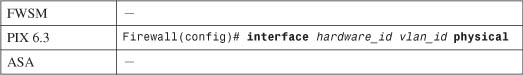
1. Define the interface as physical (Step a) or logical (Step b):
a. Define a physical interface:
The interface is referenced by its hardware-id. For example, this could be gb-ethernet1 in PIX 6.3 or GigabitEthernet1 on an ASA.
In PIX 6.3, the interface medium’s speed and duplex mode are given by one of the following hardware-speed values:
Beginning with ASA 7.0, the interface speed and duplex are configured with separate interface configuration commands. By default, an interface uses autodetected speed and autonegotiated duplex mode.
Tip
By default, interfaces are administratively shut down. To enable an interface in PIX 6.3, use the interface configuration command without the shutdown keyword. For PIX 7.3, use the no shutdown interface configuration command.
To disable or administratively shut down an interface, add the shutdown keyword.
b. (Optional) Define a logical VLAN interface:
Logical VLAN interfaces must be carried over a physical trunk interface, identified as hardware_id (gb-ethernet0 or GigabitEthernet0, for example). In PIX 6.3, the VLAN interface itself is identified by vlan_id, a name of the form vlanN (where N is the VLAN number, 1 to 4095). The logical keyword makes the VLAN interface a logical one.
On an ASA, a subinterface number is added to the physical interface name to create the logical interface. This is an arbitrary number that must be unique for each logical interface. The VLAN number is specified as vlan_id in a separate vlan subinterface configuration command.
Packets being sent out a logical VLAN interface are tagged with the VLAN number as they enter the physical trunk link. The VLAN number tag is stripped off at the far end of the trunk, and the packets are placed on the corresponding VLAN. The same process occurs when packets are sent toward the firewall on a VLAN.
The trunk encapsulation used is always IEEE 802.1Q, and the tagging encapsulation and unencapsulation are automatically handled at each end of the trunk. Make sure the far-end switch is configured to trunk unconditionally. For example, the following Catalyst IOS switch configuration commands could be used:
Switch(config)# interface gigabitethernet 0/1
Switch(config-if)# switchport
Switch(config-if)# switchport trunk encapsulation dot1q
Switch(config-if)# switchport mode trunk
By default, any packets that are sent out the firewall’s physical interface itself are not tagged, and they appear to use the trunk’s native VLAN. These packets are placed on the native VLAN number of the far-end switch port.
If you intend to use logical VLAN interfaces on a physical firewall interface that is trunking, you should never allow the trunk’s native VLAN to be used. You can do this by configuring a VLAN number on the physical interface, too. After this is done, the firewall cannot send packets across the trunk untagged.
By default, Cisco switches use VLAN 1 as the native (untagged) VLAN on all trunk links. Be aware that the native VLAN can be set to any arbitrary VLAN number on a switch. Find out what native VLAN is being used, and choose a different VLAN number on the firewall’s physical interface.
Also make sure that the switch is using something other than the native VLAN to send packets to and from the firewall. The idea is to use only VLANs that are defined specifically to pass data to and from the firewall while eliminating the possibility that an unexpected VLAN appears on the trunk. For example, you could use the following commands on a Catalyst switch to set a trunk’s native VLAN to VLAN 7 and to allow only VLANs 100 through 105 to pass over the trunk to the firewall:
SwitchIconfig)# interface gigabitethernet 1/1
Switch(config-if)# switchport
Switch(config-if)# switchport trunk native vlan 7
Switch(config-if)# switchport trunk allowed vlan 100-105
Switch(config-if)# switchport mode trunk
You can use the following configuration command to force the firewall to tag packets on the physical firewall trunk interface, too:
Again, the VLAN is identified by vlan_id, a name of the form vlanN (where N is the VLAN number, 1 to 4095). The physical keyword makes the logical VLAN interface overlay with the physical interface so that any packets passing over the interface receive a VLAN ID tag.
After a VLAN has been assigned to the physical interface, the firewall drops any untagged packets that are received over the trunk interface’s native VLAN.
This step is unnecessary beginning with an ASA, because the physical interface is configured with the no nameif command by default, which forces all traffic to pass through one or more subinterfaces that are configured with a VLAN number, requiring a VLAN tag.
Tip
After a VLAN number has been assigned to a logical interface, it is possible to change the VLAN number. You can use this PIX 6.3 configuration command to change from the old VLAN name to a new one:
Firewall(config)# interface hardware_id change-vlan old-vlan-id
new-vlan-id
2. (Optional) Name the interface:
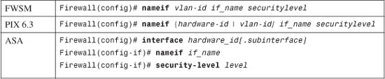
Here, the physical interface is identified by its hardware-id (gb-ethernet0, for example) or vlan-id (vlan5, for example; the word vlan is always present). If multiple-security context mode is being used, the vlan-id or hardware-id could be an arbitrary name that has been mapped to the context by the allocate-interface command in the system execution space.
The interface is given the arbitrary name if_name (1 to 48 characters) that other firewall commands can use to refer to it. By default, the “inside” and “outside” names are predefined to two interfaces. You can change those assignments, and you can use entirely different names if you want.
A security level is also assigned to the interface as securitylevel (where level is a number 0 to 100, from lowest to highest). PIX 7.3 is the exception, where the security level is given with the keyword security-level, followed by the level number (0 to 100). Security levels 0 and 100 are reserved for the “outside” and “inside” interfaces, respectively. Other perimeter interfaces should have levels between 1 and 99.
For example, the outside interface could be configured as follows:
Note
Security levels are used only to determine how the firewall inspects and handles traffic. For example, traffic passing from a higher-security interface toward a lower one is assumed to be going toward a less-secure area. Therefore, it is forwarded with less-stringent policies than traffic coming in toward a higher-security area.
In addition, firewall interfaces must have different security levels. The only exceptions are with ASA and FWSM 2.2+, which allow interfaces to have the same security level only if the same-security-traffic permit inter-interface global configuration command has been used. In that case, traffic is forwarded according to policies set by access lists, with no regard to higher or lower security levels.
3. Assign an IP address.
You can assign a static IP address if one is known and available for the firewall. Otherwise, you can configure the firewall to request an address from either a DHCP server or through PPPoE. (Your ISP should provide details about obtaining an address.) Choose one of the following steps:
a. (Optional) Assign a static address:
Firewall(config)# ip address if_name ip_address [netmask]
If you have a static IP address that the firewall can use, you can assign it here. The interface named if_name (inside or outside, for example) uses the IP address and subnet mask given.
If you omit the netmask parameter, the firewall assumes that a classful network (Class A, B, or C) is being used.
For example, if the first octet of the IP address is 1 through 126 (1.0.0.0 through 126.255.255.255), a Class A netmask (255.0.0.0) is assumed.
If the first octet is 128 through 191 (128.0.0.0 through 191.255.255.255), a Class B netmask (255.255.0.0) is assumed.
If the first octet is 192 through 223 (192.0.0.0 through 223.255.255.255), a Class C netmask (255.255.255.0) is assumed.
If you use subnetting in your network, be sure to specify the correct netmask rather than the classful mask (255.0.0.0, 255.255.0.0, or 255.255.255.0) that the firewall derives from the IP address.
b. (Optional) Obtain an address via DHCP:
Firewall(config)# ip address outside dhcp [setroute] [retry retry_cnt]
Generally, the outside interface points toward an ISP. Therefore, the firewall can generate DHCP requests from that interface. If no reply is received, the firewall retries the request up to retry_cnt times (4 to 16; the default is 4).
You can also set the firewall’s default route from the default gateway parameter returned in the DHCP reply. To do this, use the setroute keyword; otherwise, you have to explicitly configure a default route.
Tip
You can release and renew the DHCP lease for the outside interface by entering this configuration command again.
c. (Optional) Obtain an address through PPPoE.
A PIX or an ASA (beginning with release 8.0) platform can use a PPPoE client to make a broadband connection to an ISP. Point-to-Point Protocol over Ethernet (PPPoE) is a practical way of using the firewall’s physical Ethernet interface to communicate with an ISP over traditional PPP infrastructure. PPPoE is supported only when the firewall is configured for single context, routed mode, without failover.
Like PPP, PPPoE requires the remote access client (the ASA, in this case) to authenticate and obtain network parameters before it can begin communicating over the link. To do this, the firewall uses a Virtual Private Dialup Network (VPDN) group. The group specifies the authentication method and the username and password credentials assigned by the ISP. You can use the following steps to configure the PPPoE client:
— Define a username for PPPoE authentication:
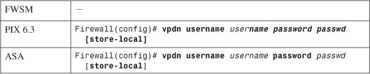
The firewall authenticates itself with an ISP using a username username (a text string) and password passwd (an unencrypted text string). You can repeat this command to define multiple usernames and passwords if several ISPs are possible.
By default, the username and password are entered into the firewall configuration as a part of this command. If you use a management tool such as Cisco Security Manager (CSM) or CiscoWorks Firewall Management Center to deploy the firewall, a template configuration might overwrite a valid username and password. You can choose to store the username and password locally in the firewall’s Flash memory by adding the store-local keyword.
— (Optional) Define a VPDN group to contain PPPoE parameters:
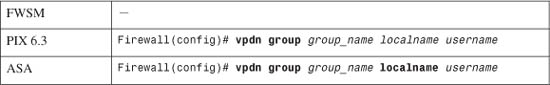
The firewall can associate PPPoE parameters into groups such that one group is used to negotiate with one ISP. Here, the group_name is an arbitrary name (up to 63 characters) that points to a locally defined username username and password pair. This pair should already be configured with the vpdn username username command.
— Set the PPPoE authentication method:
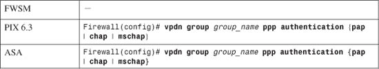
For the VPDN group, you should use the same authentication method that your ISP uses: pap (Password Authentication Protocol, with cleartext exchange of credentials), chap (Challenge Handshake Authentication Protocol, with encrypted exchange), or mschap (Microsoft CHAP, version 1 only).
— Enable PPPoE requests using a VPDN group:
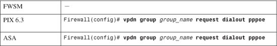
The firewall builds PPPoE requests using the parameters defined in VPDN group group_name.
— Request IP address information on the outside interface:
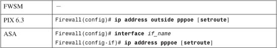
The firewall sends PPPoE requests on its outside interface to authenticate and obtain an IP address and subnet mask from the ISP. If the default gateway that is returned should be used as the firewall’s default route, add the setroute keyword. Otherwise, a default route must be configured manually on the firewall.
You can renegotiate the address parameters with the ISP by entering this configuration command again.
Tip
If you already have a static IP address assigned by the ISP, you can use an alternative command:
Firewall(config)# ip address outside ip-address netmask pppoe [setroute]
Here, the IP address and netmask are already known. The firewall still authenticates with the ISP through PPPoE, but it uses these values rather than negotiating them.
As an example of PPPoE interface configuration, the following commands can be used to define a VPDN group for one ISP that can be used by the firewall:
Firewall(config)# vpdn username JohnDoe password JDsecret
Firewall(config)# vpdn group ISP1 localname JohnDoe
Firewall(config)# vpdn group ISP1 ppp authentication chap
Firewall(config)# vpdn group ISP1 request dialout pppoe
Firewall(config)# ip address outside pppoe setroute
4. Test the interface:
a. Verify the IP address:
Firewall# show ip
or
Firewall# show ip if_name {dhcp | pppoe}
b. Ping the next-hop gateway address:
Firewall# ping [if_name] ip_address
You can send ICMP echo requests to the next-hop gateway or a host located on the same subnet as the firewall interface. You can specify which firewall interface name to use with if_name, but this is not required. The target is at ip_address.
If ICMP replies are received, they are reported along with the round-trip time, as in this example:
Firewall# ping 192.168.199.4
192.168.199.4 response received -- 0ms
192.168.199.4 response received -- 30ms
192.168.199.4 response received -- 0ms
Firewall#
c. Verify PPPoE operation:
As soon as the PPPoE client is configured and the interface is connected and is operational, the firewall automatically attempts to bring up the PPPoE connection. You can see the status with the following command:
Firewall# show vpdn session
For example, if the PPPoE client has negotiated its connection, you might see the following output:
Firewall# show vpdn session
PPPoE Session Information (Total tunnels=1 sessions=1)
Remote Internet Address is 192.168.11.1
Session state is SESSION_UP
Time since event change 10002 secs, interface outside
PPP interface id is 1
36 packets sent, 36 received, 1412 bytes sent, 0 received
Firewall#
If the PPPoE connection does not come up normally, you can use the debug pppoe event command to see PPPoE negotiation events as they occur.
Interface Configuration Examples
A firewall has three interfaces:
• inside (gb-ethernet0)
• outside (gb-ethernet1)
• dmz (gb-ethernet2)
These interfaces have IP addresses 172.16.1.1, 172.17.1.1, and 172.18.1.1, respectively. The configuration commands needed are as follows, for both PIX 6.3 and ASA releases:
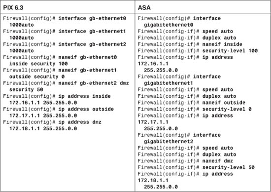
Now consider the same scenario with an FWSM in slot 3 of a Catalyst 6500 switch. The inside, outside, and dmz interfaces are all logical, as VLANs 100, 200, and 300, respectively:
Switch(config)# firewall vlan-group 1 100,200,300
Switch(config)# firewall module 3 vlan-group 1
Switch(config)# exit
Switch# session slot 3 processor 1
Firewall# configure terminal
Firewall(config)# nameif vlan100 inside security100
Firewall(config)# nameif vlan200 outside security0
Firewall(config)# nameif vlan300 dmz security50
Firewall(config)# ip address inside 172.16.1.1 255.255.0.0
Firewall(config)# ip address outside 172.17.1.1 255.255.0.0
Firewall(config)# ip address dmz 172.18.1.1 255.255.0.0
As a final example, consider an ASA or PIX Firewall in a similar scenario. Here, a single physical interface (gb-ethernet0) is configured as a trunk. The inside, outside, and dmz interfaces are all logical, as VLANs 100, 200, and 300, respectively. The configuration commands needed are shown as follows for both the PIX 6.3 and ASA releases:
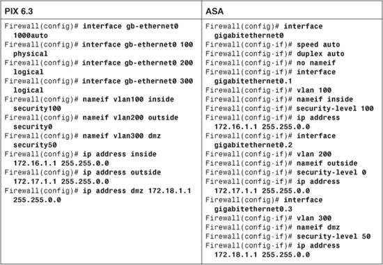
In the PIX 6.3 configuration, notice that VLAN 100 has been configured on the “physical” portion of the gb-ethernet0 interface. This ensures that VLAN 100 is tagged on the trunk, along with VLANs 200 and 300. In fact, nothing is sent or received untagged on the firewall’s trunk.
To configure similar behavior on an ASA, the no nameif command is added to the physical interface (gigabitethernet0) configuration. In effect, this prevents the physical interface from becoming active, other than carrying VLAN traffic as a trunk link.
Configuring IPv6 on an Interface
Beginning with ASA 7.0, firewall interfaces can be configured with an IPv6 address in addition to a traditional IPv4 address. IPv6 addresses are 128 bits long—much longer than a 32-bit IPv4 address! As well, the IPv6 address format is very different and can be written in the following ways:
• In full hexadecimal format, the address is written as eight groups of four hexadecimal digits, with colons separating the groups. For example, 1111:2222:3333:4444:5555:6666:7777:8888 represents a single IPv6 host.
• Leading 0s can be omitted in any group. For example, 1111:0200:0030:0004:5555:6666:7777:8888 can also be written as 1111:200:30:4:5555:6666:7777:8888.
• Because IPv6 addresses are so long and the address space is so large, addresses with many embedded 0s are common. Therefore, you can abbreviate any number of contiguous 0s as a double colon (::), even if the 0s cross a digit group boundary. For example, 1111:0:0:0:0:0:0:8888 could also be written as 1111::8888. This abbreviation can be used only once in an address, however.
• IPv6 addresses can also be shown with a network prefix. This specifies how many most-significant bits are used to represent a network address. This is very similar to IPv4 addresses, where the address and prefix values are separated by a slash (/). For IPv6, this format is also ipv6_address/prefix_length, where the prefix length is a value from 1 to 128 bits.
Each firewall interface can potentially have three different IPv6 addresses configured:
• Link-local address—An address that is unique on a network connection to other devices. This is used only for IPv6 neighbor discovery, address autoconfiguration, and administrative uses. A firewall cannot forward packets that have link-local addresses as the destination. The address format consists of the following components:
— FE80 in the 10 most-significant bits
— 54 bits of 0s
— 64 bits of host addressing in the modified EUI-64 format
• Site-local address—A unique address within the site network that cannot be routed outside the site. The address consists of the following components:
— FEC0 in the 10 most-significant bits
— 38 bits of 0s
— 16 bits of subnet ID addressing
— 64 bits of host addressing
• Global address—A globally unique address that can be routed outside the local link and local network. The address consists of the following components:
— 001 in the 3 most-significant bit positions
— 45 bits of provider addressing (unique to each service provider)
— 16 bits of site or subnet addressing (unique only within the local site network)
— 64 bits of host addressing (48 bits usually come from the MAC address)
After you configure IPv6 addresses and routing information, the firewall can begin to statefully inspect traffic using IPv6. The following inspection engines are equipped to inspect either IP version:
• ICMP
• UDP
• FTP
• SMTP
• HTTP
• SIP (beginning with ASA 8.0)
You can follow these steps to configure IPv6 on your firewall:
1. Select a firewall interface:
Firewall(config)# interface hardware-id
The interface is identified by its hardware-id, which is the full interface type and number or an abbreviated version. For example, GigabitEthernet 0, GigabitEthernet0, and gig0 all refer to the same interface.
2. Assign an IPv6 address to an interface.
a. (Optional) Use autoconfiguration to derive interface addresses.
A firewall can use stateless autoconfiguration to derive link-local and global addresses for an interface. Use the following commands to enable autoconfiguration:
Firewall(config-if)# ipv6 address autoconfig
Firewall(config-if)# ipv6 enable
The firewall first creates a link-local address for the interface. This can be done without any knowledge of surrounding networks or neighboring devices. The link-local address is formed as follows, building digits from least- to most-significant (right to left):
— The three least-significant octets are the three least-significant octets of the MAC address.
— The three most-significant octets of the MAC address become the three next-most-significant octets of the link-local address.
In addition, the next-to-least-significant bit of the most-significant MAC address byte is set to 1. For example, 0003.47 would become 0203.47.
The most-significant address digits always begin with FE80.
For example, consider the following firewall interface. You can use the show interface command to display the interface’s MAC address, which is 0003.4708.ec54. When the autoconfiguration is complete, the IPv6 link-local address can be seen with the show ipv6 interface command. Here, the link-local address has become fe80::203:47ff:fe08:ec54:
Firewall# show interface gigabitethernet 1.2
Interface GigabitEthernet1.2 "inside", is up, line protocol is up
VLAN identifier 2
MAC address 0003.4708.ec54, MTU 1500
IP address 192.168.198.1, subnet mask 255.255.255.0
Received 1482892 packets, 81328736 bytes
Transmitted 311834 packets, 24639862 bytes
Dropped 1060893 packets
Firewall#
Firewall# show ipv6 interface inside
inside is up, line protocol is up
IPv6 is enabled, link-local address is fe80::203:47ff:fe08:ec54
No global unicast address is configured
Joined group address(es):
ff02::1
ff02::2
ff02::1:ff08:ec54
[output omitted]
The global interface address has a similar form, but it begins with the prefix learned from a neighboring router. A modified EUI-64 address is used, which includes the ff:fe and MAC address portions.
After a prefix has been learned from router advertisements, you can display the global address with the show ipv6 interface command, as in the following example:
Firewall# show ipv6 interface inside
inside is up, line protocol is up
IPv6 is enabled, link-local address is fe80::203:47ff:fe08:ec54
Global unicast address(es):
1999::203:47ff:fe08:ec54, subnet is 1999::/64 [AUTOCONFIG]
valid lifetime 2591959 preferred lifetime 604759
Joined group address(es):
ff02::1
ff02::2
ff02::1:ff08:ec54
[output omitted]
b. (Optional) Specify a link-local address:
Firewall(config-if)# ipv6 address ipv6_address link-local
You can assign a specific link-local address as ipv6_address if autoconfiguration is not wanted.
c. (Optional) Specify a complete global IPv6 address:
Firewall(config-if)# ipv6 address ipv6_address/prefix_length [eui-64]
You can specify the complete global address as ipv6_address. The prefix_length (1 to 128) specifies the number of most-significant address bits reserved for the network address. The global address must be unique within the IPv6 network.
You can also use the eui-64 keyword to let the firewall build a unique modified EUI-64 address format. The ipv6_address value is used for the upper 64 bits. The lower 64 bits of the address are the upper three octets of the interface MAC address, ff:fe, and the lower three MAC address octets.
3. Use IPv6 neighbor discovery to learn about neighboring devices.
A firewall can participate in IPv6 neighbor discovery to learn about other directly connected devices. Neighbor discovery is always enabled. You can follow these steps to adjust the neighbor discovery operation:
a. (Optional) Set the neighbor solicitation interval:
Firewall(config-if)# ipv6 nd ns-interval value
The firewall sends neighbor solicitation messages at the interval value (1000 to 3,600,000 milliseconds [ms]; the default is 1000 ms or 1 second).
b. (Optional) Set the neighbor reachability time:
Firewall(config-if)# ipv6 nd reachable-time value
If the neighboring device becomes unreachable, the firewall can send neighbor solicitation messages in an attempt to get a response. The firewall waits for value milliseconds (0 to 3,600,000; the default is 0) before declaring the neighbor unreachable. A value of 0 means that the firewall advertises an unspecified reachability time to its neighbors and does not measure this time itself.
c. (Optional) Adjust duplicate address detection (DAD):
Firewall(config-if)# ipv6 nd dad attempts value
A firewall attempts to check to see if another device is using its own interface link-local address. If a duplication is detected, no IPv6 data is processed on the interface.
If the link-local address is not duplicated, the firewall checks for a duplicate of its interface global IPv6 address.
The firewall sends value (0 to 600; the default is 1) neighbor solicitation messages to detect a duplicate address. If value is set to 0, no DAD is performed.
Tip
If a directly connected IPv6 neighbor cannot be discovered automatically, you can define it as a static entry. Use the following global configuration command to define and locate the neighboring device:
Firewall(config)# ipv6 neighbor ipv6_address if_name mac_address
The neighbor uses the local data-link address ipv6_address and MAC address mac_address (xxxx.xxxx.xxxx hex format). As well, the neighbor can be found on the firewall interface named if_name (outside, for example).
Suppose a neighboring device connected to the inside interface uses IPv6 local data-link address fe80::206:5bff:fe02:a841 and MAC address 0006.5b02.a841. You could use the following command to define a static neighbor entry:
Firewall(config)# ipv6 neighbor fe80::206:5bff:fe02:a841 inside
0006.5b02.a841
4. Configure IPv6 router advertisements on the interface.
As a Layer 3 IPv6 device, a firewall can participate in router advertisements so that neighboring devices can dynamically learn a default router address. You can follow these steps to configure how the firewall carries out its router advertisement process:
a. (Optional) Stop sending router advertisements:
Firewall(config-if)# ipv6 nd suppress-ra
By default, a firewall acts as an IPv6 router if IPv6 is enabled and the interface has an IPv6 address. The firewall sends periodic router advertisements to neighboring IPv6 devices, announcing itself as a router.
You can use the ipv6 nd suppress-ra command to stop sending router advertisements. In this case, the firewall appears as a regular IPv6 neighbor or node. Neighbor discovery is active even when router advertisements are suppressed.
b. (Optional) Set the router advertisement interval:
Firewall(config-if)# ipv6 nd ra-interval [msec] value
By default, a firewall sends router advertisements out an IPv6 interface every 200 seconds. You can adjust the interval to value (3 to 1800 seconds, or 500 to 1,800,000 ms if the msec keyword is given).
c. (Optional) Adjust the lifetime of router advertisements:
Firewall(config-if)# ipv6 nd ra-lifetime seconds
By default, router advertisements are sent with a valid lifetime of 1800 seconds. Neighboring devices can expect the firewall to be a default router for the duration of the lifetime value.
You can adjust the lifetime to seconds (0 to 9000 seconds). A value of 0 indicates that the firewall should not be considered a default router on the advertising interface.
5. (Optional) Configure IPv6 prefixes to advertise.
By default, a firewall advertises the prefix from any IPv6 address that is configured on an interface. The prefix advertisement can be used by neighboring devices to autoconfigure their interface addresses.
In the commands covered in Steps 5a through 5d, you can use the default keyword to define lifetimes for all prefixes that are advertised. Otherwise, you can specify an IPv6 prefix as ipv6_address/prefix_length. The prefix_length is the number of the most-significant bits used as a network prefix, from 1 to 128.
You can also add the no-autoconfig keyword to advertise that the prefix should not be used for autoconfiguration. By default, any prefix that is advertised is assumed to be “on link,” meaning that it is used on the advertising interface. You can add the off-link keyword to specify a prefix that is not configured on the firewall interface.
a. (Optional) Advertise a prefix with default lifetime values:
Firewall(config-if)# ipv6 nd prefix {default |
ipv6_address/prefix_length} [no-autoconfig] [off-link]
By default, the prefix is advertised with a valid lifetime of 30 days (2,592,000 seconds) and a preferred lifetime of 7 days (604,800 seconds).
For example, the following command causes the IPv6 prefix 1999::/64 to be advertised with the default values:
Firewall(config)# ipv6 nd prefix 1999::/64
b. (Optional) Advertise a prefix with predefined lifetime values:
Firewall(config-if)# ipv6 nd prefix {default |
ipv6_address/prefix_length} valid_lifetime preferred_lifetime
[no-autoconfig] [off-link]
The prefix is advertised with a valid lifetime of valid_lifetime (0 to 4,294,967,295 or infinite seconds). The prefix also is advertised as a preferred prefix lasting preferred_lifetime (0 to 4,294,967,295 or infinite seconds).
To advertise the prefix 1999::/64 with a valid lifetime of 5 days (432,000 seconds) and a preferred lifetime of 1 day (86,400 seconds), you could use the following command:
Firewall(config)# ipv6 nd prefix 1999::/64 432000 86400
c. (Optional) Advertise a prefix with an expiration date:
Firewall(config-if)# ipv6 nd prefix {default |
ipv6_address/prefix_length} at valid_date_time preferred_date_time
[no-autoconfig] [off-link]
The prefix is advertised to remain valid until the specific date and time are reached. The valid lifetime is given as valid_date_time, and the prefix is preferred until preferred_date_time is reached.
Each date and time value is given in this form:
{month day | day month} hh:mm
The month is the month name, given as at least three characters. The day is 1 to 31. The time is always given in 24-hour format.
For example, suppose the prefix 1999::/64 is advertised to expire at 23:59 on December 31 for the valid and preferred lifetimes. You could use the following command to accomplish this:
Firewall(config)# ipv6 nd prefix 1999::/64 dec 31 23:59 dec 31 23:59
d. (Optional) Do not advertise a prefix:
Firewall(config-if)# ipv6 nd prefix {default |
ipv6_address/prefix_length} no-advertise
The prefix given is not advertised.
Testing IPv6 Connectivity
As soon as you configure IPv6 operation on a firewall, make sure each of the respective interfaces has an IPv6 address. An interface must have a link-local address to communicate with its neighbors. An interface must also have a global address to be able to forward packets to other IPv6 destination addresses. You can display these addresses with the show ipv6 interface command.
You can display any other IPv6 routers that the firewall has discovered from router advertisements it has received. Confirm any entries seen with the show ipv6 routers command, as in the following example:
Firewall# show ipv6 routers
Router fe80::260:70ff:fed7:8800 on inside, last update 1 min
Hops 64, Lifetime 1800 sec, AddrFlag=0, OtherFlag=0, MTU=1500
Reachable time 0 msec, Retransmit time 0 msec
Prefix 1999::/64 onlink autoconfig
Valid lifetime 2592000, preferred lifetime 604800
Firewall#
From the fe80 digits in the most-significant IPv6 address positions, you can distinguish the router address shown as a link-local address.
You can also use a form of the ping command to send IPv6 ICMP echo packets to a neighboring device with the following simplified syntax:
Firewall# ping [if_name] ipv6_address
With the preceding router example, you could ping the router’s IPv6 link-local address to determine good connectivity and a working IPv6 configuration. The following example shows an attempted ping:
Firewall# ping fe80::260:70ff:fed7:8800
Sending 5, 100-byte ICMP Echos to fe80::260:70ff:fed7:8800, timeout is 2 seconds:
Interface must be specified for link-local or multicast address
Success rate is 0 percent (0/1)
Firewall#
Because a link-local address is being used as the ping target, the firewall cannot determine which of its interfaces to use. This is because link-local addresses do not include any network or route information that could be used to find a destination interface. The example is repeated with the interface information as follows, showing a series of successful ICMP echo and reply packets:
Firewall# ping inside fe80::260:70ff:fed7:8800
Sending 5, 100-byte ICMP Echos to fe80::260:70ff:fed7:8800, timeout is 2 seconds:
!!!!!
Success rate is 100 percent (5/5), round-trip min/avg/max = 1/1/1 ms
Firewall#
Configuring the ARP Cache
A firewall maintains a cache of Address Resolution Protocol (ARP) entries that are learned when it overhears ARP requests or ARP reply packets on its interfaces. ARP is used to resolve a host’s MAC address based on its IP address, and vice versa.
You can use the following commands to configure ARP operations:
1. Define a static ARP entry:
Firewall(config)# arp if_name ip_address mac_address [alias]
ARP entries normally are created as the firewall hears responses to ARP requests on each interface. There might be times when you need to configure a static entry for hosts that do not answer ARP requests on their interfaces. Static ARP entries do not age out over time.
Specify the firewall interface name if_name (inside or outside, for example) where the host can be found. The host’s IP address and MAC address (in dotted-triplet format) must also be given.
Use the alias keyword to create a static proxy ARP entry, where the firewall responds to ARP requests on behalf of the configured host IP address—whether or not it actually exists.
For example, you can use the following command to configure a static ARP entry for a machine that can be found on the inside interface. Its MAC address and IP address are 0006.5b02.a841 and 192.168.1.199, respectively:
Firewall(config)# arp inside 0006.5b02.a841 192.168.1.199
2. Set the ARP persistence timer:
Firewall(config)# arp timeout seconds
ARP entries dynamically collected are held in the firewall’s cache for a fixed length of time. During this time, no new ARP information is added or changed for a specific cached host address. By default, ARP entries are held for 14,400 seconds (4 hours). You can set the persistence timer to seconds (1 to 1,215,752 seconds for PIX 6.3 or 60 to 4,294,967 seconds for ASA and FWSM).
You can display the current ARP cache contents with the following command:
Firewall# show arp [statistics]
For example, the following ARP entries have been created on a firewall:
Firewall# show arp
stateful 192.168.199.1 0030.8587.546e
lan-fo 192.168.198.2 0030.8587.5433
outside 12.16.11.1 0003.4725.2f97
outside 12.16.11.2 0005.5f93.37fc
outside 12.16.11.3 00d0.01e6.6ffc
inside 192.168.1.1 0003.4725.2e32
inside 192.168.1.4 00d0.0457.3bfc
inside 192.168.1.3 0007.0d55.a80a
Firewall#
Be aware that the firewall maintains ARP entries for its own interfaces too, as indicated by the gray shaded entries.
You can add the statistics keyword to display counters for various ARP activities. Consider the following output:
Firewall# show arp statistics
Number of ARP entries:
PIX : 11
Dropped blocks in ARP: 10
Maximum Queued blocks: 17
Queued blocks: 0
Interface collision ARPs Received: 0
ARP-defense Gratuitous ARPS sent: 0
Total ARP retries: 70
Unresolved hosts: 0
Maximum Unresolved hosts: 2
Firewall#
Tip
If a host’s IP address changes or its network interface is replaced, an existing ARP entry can become stale and will be stuck in the firewall’s ARP table until it expires. If this happens, you can clear the entire ARP cache contents by using the clear arp EXEC command.
If you decide to clear the ARP cache, you should do so only during a maintenance time when the network is not busy; otherwise, there might be a pause in network traffic passing through the firewall while the ARP cache is being rebuilt.
Although you cannot clear individual ARP cache entries, you can configure a static ARP entry for the IP address in question so that it is paired with a bogus MAC address. After that is done, remove the command that was just used. The bogus static ARP entry is removed, and the firewall relearns an ARP entry based on dynamic information from the host.
Configuring Interface MTU and Fragmentation
By default, any Ethernet interface has its maximum transmission unit (MTU) size set to 1500, which is the maximum and expected value for Ethernet frames. If a packet is larger than the MTU, it must be fragmented before being transmitted. You can use the following command to adjust an interface MTU:
Firewall(config)# mtu if_name bytes
If you need to, you can adjust the MTU of the interface named if_name to the size bytes (64 to 65,535 bytes). In some cases, you might need to reduce the MTU to avoid having to fragment encrypted packets where the encryption protocols add too much overhead to an already maximum-sized packet.
Cisco firewalls can participate in MTU discovery along an end-to-end IP routing path. This process follows RFC 1191, where the MTU is set to the smallest allowed MTU along the complete path.
You can display the current MTU configuration for all firewall interfaces by using the show mtu (PIX 6.3) or show running-config mtu (ASA and FWSM) command. Interface MTU settings are also displayed as a part of the show interface EXEC command output.
For example, the following output represents the MTU settings on a firewall’s outside interface:
Firewall# show running-config mtu
mtu outside 1500
mtu inside 1500
mtu dmz 1500
Firewall#
Firewall# show interface
Interface GigabitEthernet0 "", is up, line protocol is up
Hardware is i82542 rev03, BW 1000 Mbps
(Full-duplex), Auto-Speed(1000 Mbps)
Available but not configured via nameif
MAC address 0003.4708.ec54, MTU not set
IP address unassigned
17786900 packets input, 21111200936 bytes, 0 no buffer
Received 171 broadcasts, 0 runts, 0 giants
0 input errors, 0 CRC, 0 frame, 0 overrun, 0 ignored, 0 abort
131444 packets output, 89823504 bytes, 0 underruns
0 output errors, 0 collisions
0 late collisions, 191 deferred
input queue (curr/max blocks): hardware (0/25) software (0/0)
output queue (curr/max blocks): hardware (0/5) software (0/0)
Interface GigabitEthernet1.2 "outside", is up, line protocol is up
VLAN identifier 2
MAC address 0003.4708.ec54, MTU 1500
IP address 10.1.1.1, subnet mask 255.0.0.0
Received 17683308 packets, 20714401393 bytes
Transmitted 119650 packets, 86481250 bytes
Dropped 95017 packets
[output for other interfaces omitted]
Notice that the outside interface is actually a logical interface (GigabitEthernet1.2) representing a VLAN on a physical trunk interface (GigabitEthernet1). An MTU is set only when the nameif command has been configured for an interface, as in the case of the logical interface named outside.
Tip
Hosts using TCP connections can also negotiate the maximum segment size (MSS) that is used. This is done as a TCP connection is initiated, and it occurs on a per-connection basis. As a result, an MSS value can sometimes be chosen that is larger than the MTU being used along the path. This also results in TCP packets being fragmented so that they can be forwarded.
You can configure the firewall to govern the maximum MSS value negotiated on connections passing through it. The firewall overrides any request for an MSS value larger than its limit, and it replaces the MSS value in the TCP packet so that the negotiation is transparent to the end hosts.
You can use the following command to limit the TCP MSS size in all TCP connections:
Firewall(config)# sysopt connection tcpmss [minimum] bytes
By default, the TCP MSS must be between 48 and 1380 bytes. You can adjust the maximum MSS limit to bytes or the minimum MSS to minimum bytes.
When a firewall receives packets that have been fragmented, it stores each fragment in a cache and virtually reassembles the fragments so that the original packet can be inspected. This allows the firewall to verify the order and integrity of each fragment and to discover malicious exploits that use fragmentation. This process is part of the FragGuard firewall feature.
You can configure how the firewall handles the packet fragments it receives with the following steps:
1. Limit the number of fragments awaiting reassembly:
Firewall(config)# fragment size database-limit [if_name]
By default, a firewall reserves space for 200 fragmented packets in memory per interface, where they are stored temporarily while awaiting reassembly. You can change this to database-limit packets (up to 1,000,000 or the maximum number of free 1550-byte or 16,384-byte blocks). If an interface name is not specified, the limit applies to all interfaces.
For example, the following command could be used to reserve space for 500 fragments arriving on the outside interface, awaiting virtual reassembly:
Firewall(config)# fragment size 500 outside
Tip
You can display the current status of memory blocks with the show block EXEC command. Look for the LOW value for size 1550 and 16,384 to see the fewest free blocks that have been available in the past. In most cases, however, you should keep the reassembly database size set to a low or default value to prevent fragmentation DoS attacks from using large amounts of firewall memory.
2. Limit the number of fragments per packet:
Firewall(config)# fragment chain chain-limit [if_name]
By default, a firewall accepts up to 24 fragments of a single packet before they are discarded. You can change this limit to chain-limit (up to 8200 fragments per packet) on a global or per-interface basis. If you do not specify an interface, the chain-limit value is applied to all interfaces.
Tip
You might want to consider limiting the fragment space to 1, allowing only a single fragment to be stored—the whole packet itself. Most often, legitimate applications do not fragment packets in the first place, so the firewall should not receive any fragments. Some denial-of-service attacks, on the other hand, exploit the use of fragments. You can use the following command to minimize the fragment cache for all firewall interfaces:
Firewall(config)# fragment chain 1
Be aware that such a strict limit causes the firewall to drop packet fragments from legitimate (or desired) traffic too. You should consider increasing the fragment space if you have known applications (Network File System [NFS], for example) or tunneling protocols (GRE, L2TP, or IPSec) that could require the use of fragmentation.
3. Limit the time for all parts of a packet to arrive:
Firewall(config)# fragment timeout seconds [if_name]
By default, a firewall collects fragments as they arrive for 5 seconds. If the final fragment does not arrive by then, all the fragments are discarded, and the packet is never reassembled. You can adjust the collection time to seconds (up to 30 seconds) on a global or per-interface basis. If an interface name if_name is not specified, the limit applies to all interfaces.
You can monitor a firewall’s fragmentation activity with the show fragment EXEC command. For example, the firewall interface shown in the following output has the default fragment settings (database size 200 packets, chain limit 24 fragments, and timeout limit 5 seconds). The firewall has reassembled 534 packets, and two packets are awaiting reassembly:
Firewall# show fragment outside
Interface: outside
Size: 200, Chain: 24, Timeout: 5, Threshold: 133
Queue: 2, Assemble: 534, Fail: 1097, Overflow: 12401
Firewall#
You can also see that the reassembly process has failed 1097 times. This is because the timeout limit expired while waiting for all fragments to arrive. The process has also had overflow conditions, indicating that more than 24 fragments arrived on 12,401 different packets.
Configuring an Interface Priority Queue
In Cisco firewall releases before ASA 7.0, packets are inspected and forwarded in a best-effort fashion. Firewall interfaces have input and output queues or buffers that store inbound or outbound packets temporarily as they arrive at or leave an interface. Sometimes, packets cannot be processed quickly enough to keep up with the flow, so they are buffered until they can be serviced.
A simple queue structure like this makes for simple interface operation. For example, consider the output queue. The first packet put into the queue is the first one that is taken out and transmitted. There is no differentiation between types of traffic or any quality of service (QoS) requirements. Regardless of the packet contents, packets leave the queue in the same order they went into it.
This presents a problem for time-critical data that might pass through a firewall. For example, any type of streaming audio or video must be forwarded in a predictable manner so that packets are not delayed too much before they reach their destination. Those packets also need to be forwarded at a fairly regular rate; too much variation in packet-to-packet delay (jitter) results in poor-quality audio or video at the destination.
When streaming data is mixed with other types of high-volume data passing through a firewall, the nonstreaming data can starve the streaming data flow. This can happen simply because the streaming packets get lost in a sea of other packets competing for transmission time.
A Cisco ASA can support two types of output interface queues:
• Best-Effort Queue (BEQ)—Packets are placed in this queue in an arbitrary order and are transmitted whenever possible.
• Low-Latency Queue (LLQ)—Packets are placed in this queue only when they match specific criteria. Any packets in the LLQ are transmitted ahead of any packets in the BEQ, providing priority service.
In addition, the firewall uses a hardware queue to buffer packets that will be copied directly to the physical interface hardware for transmission. Packets are pulled from the LLQ first, and then the BEQ, and then they are placed in the hardware queue. As soon as the hardware queue is full, those packets are moved into the interface’s own buffer for the actual transmission.
Figure 3-2 illustrates the interface queues available at each firewall interface, although only the outside interface is shown. Packets that will be sent out an interface are put in the BEQ by default. If a service policy has been configured for the interface, packets that match specific conditions in a class map can be marked for priority service. Only those packets are put into the LLQ.
Figure 3-2 Firewall Interface Queue Structure
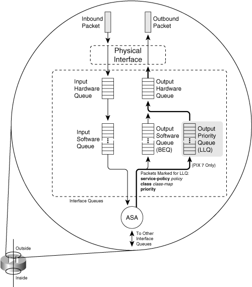
If either the BEQ or LLQ fills during a time of interface congestion, any other packets destined for the queue are simply dropped. In addition, there is no crossover or fallback between queues. If the LLQ is full, subsequent priority packets are not placed in the BEQ; they are dropped instead.
You can use the following sequence of steps to configure priority queuing:
1. Enable the priority queue on an interface:
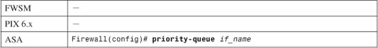
By default, only a BEQ is enabled and used on each interface. You must specifically enable a priority queue with this command for the interface named if_name (outside, for example).
Note
Priority queues are supported only on physical interfaces that have been configured with the nameif command. Trunk interfaces and other logical interfaces are not permitted to have a priority queue. Also, priority queues are not supported in multiple-security context mode.
2. (Optional) Set the queue limit:
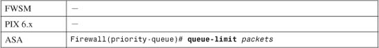
You can use this command to set the depth of both the BEQ and LLQ. The depth value packets (1 to 2048) varies according to the firewall memory and interface speed. In addition, packets can vary in size, but the queue is always measured in generic packets, which can be up to the interface MTU (1500 bytes) bytes long.
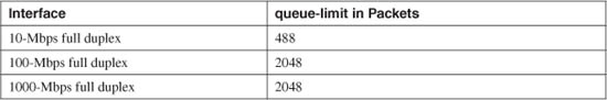
As soon as the priority queue is enabled for the first time, the queue limit is set to a calculated default value. The limit is the number of 256-byte packets that can be transmitted on the interface over a 500-ms period. Naturally, the default value varies according to the interface speed, but it always has a maximum value of 2048 packets.
For example, the default queue-limit values shown in Table 3-1 are calculated for different interface speeds.
Table 3-1 Default queue-limit Values by Interface Speed
3. (Optional) Set the transmit queue size:
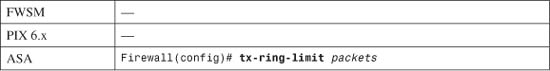
The transmit ring (tx-ring) is a virtual queue that represents a portion of the output hardware queue that is available to the Ethernet interface drivers. The transmit ring is measured in packets. It varies according to the efficiency and speed of the interface hardware.
As soon as the interface priority queue is enabled for the first time, the transmit ring limit is set to a calculated default value. The limit is the number of 1550-byte packets that can be transmitted on the interface in a 10-ms period. The packets limit has a minimum of 3 and a maximum that varies according to the interface and available memory. You can display the current maximum value through context-based help, as in the following example:
Firewall(config)# priority-queue outside
Firewall(priority-queue)# tx-ring-limit ?
priority-queue mode commands/options:
<3-128> Number of packets
Firewall(priority-queue)#
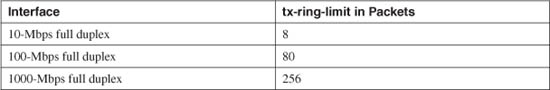
The default tx-ring-limit values shown in Table 3-2 are automatically calculated for different interface speeds.
Table 3-2 Default tx-ring-limit Values by Interface Speed
Tip
By default, all packets are sent to the best-effort queue, whether or not a priority queue has been configured and enabled. To send packets to the priority queue, you must configure a service policy that matches specific traffic with a class map and then assigns that traffic to the priority queue. Section “7-2: Defining Security Policies in a Modular Policy Framework,” in Chapter 7, “Inspecting Traffic,” covers the configuration commands needed for this task.
For example, you should configure a modular policy that has this structure:
Firewall(config)# class-map class_map_nameFirewall(config-cmap)# match conditionFirewall(config-cmap)# exitFirewall(config)# policy-map policy_map_nameFirewall(config-pmap)# class class_map_name
Firewall(config-pmap-c)# priorityFirewall(config-pmap-c)# exitFirewall(config-pmap)# exitFirewall(config)# service-policy policy_map_name interface if_name
Packets are only marked to be destined for a generic priority queue. When they are actually placed in an output queue, the firewall chooses the priority queue on the appropriate interface.
Displaying Information About the Priority Queue
You can display the current priority-queue limits with the following command:
Firewall# show running-config all priority-queue if_name
If you configure specific queue-limit or tx-ring-limit values, those are shown as part of the running configuration. However, if the priority queue uses the default values, you can see them only by displaying the default commands and parameters in the running configuration with the show running-config all keywords.
For example, the following output shows the outside interface queue limit values:
Firewall# show running-config all priority-queue outside
priority-queue outside
queue-limit 2048
tx-ring-limit 256
Firewall#
You can also get an idea about the priority queue operation on an interface with the following command:
Firewall# show service-policy interface if_name priority
You can display overall statistics for both BEQ and LLQ interface queues with the following command:
Firewall# show priority-queue statistics [if_name]
These commands are covered in more detail in “Packet Queue Status,” as covered in Section “11-1: Packet Queue Status,” as covered in Section “Checking Firewall Vital Signs,” in Chapter 11, “Verifying Firewall Operation.”
Firewall Topology Considerations
The basic principle behind using a firewall is to isolate the inside (secure) network from the outside (unsecure) network. Only through careful inspection and tightly controlled security policies are packets allowed to pass through a firewall.
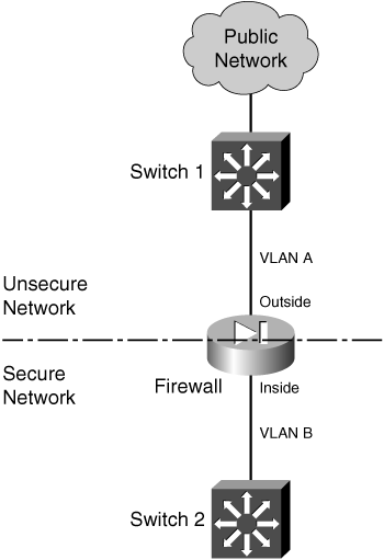
Ideally, a firewall should be located between physically separate, isolated networking equipment. For example, if a firewall is used in a switched environment, its inside and outside interfaces should connect to two different switches—the inside interface to one switch and the outside interface to a different switch, as illustrated in Figure 3-3. Notice that the inside and outside interfaces are connected to two different VLANs and that it is impossible for outside traffic to pass to the inside without proper inspection by the firewall.
Figure 3-3 A Simple Example of a Best-Practice Firewall Topology
In some environments, the use of separate switches on each side of a firewall might be too expensive. A single switch can carry multiple VLANs, each logically isolated from the others. Why not connect several of a firewall’s interfaces to just one switch, each interface assigned to a different VLAN? Along the same lines, a firewall could connect to a switch using only a single physical interface. Each logical interface could be carried over that interface as a trunk, where the VLANs are naturally isolated in the switch, as illustrated in Figure 3-4.
Figure 3-4 Using a Single Switch to Support a Firewall
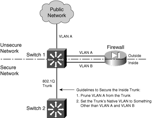
You can use a single switch to support multiple firewall interfaces. The inherent VLAN isolation works well with the inherent security isolation. However, you should carefully consider a few issues if you decide to connect a firewall in this fashion.
First, you should always be sure to prune any unused VLANs from trunk links that connect the firewall/switch combination to other networks. The basic idea is that no VLAN is allowed to extend from the outside, unsecure network into the inside, secure network without passing through the firewall first. If a VLAN does extend on in, there will always be the possibility that it can be exploited for a malicious attack or a compromise.
In Figure 3-4, VLAN A carries traffic to the firewall’s outside interface. VLAN A should be pruned from the trunk link between Switch 1 and Switch 2 so that it is contained outside the secure internal network.
Securing Trunk Links Connected to Firewalls
Another thing to consider is the potential for an exploit called VLAN hopping. When a VLAN on the public side of a boundary switch extends on into the internal side as a trunk’s native VLAN, it can be used to carry unexpected traffic that can “hop” over to a different VLAN. This can occur even if the native VLAN is not intended to carry any traffic into the inside network.
VLAN hopping occurs when someone can send packets on the outside VLAN as if they are encapsulated for an 802.1Q trunk. The boundary switch accepts the packets and then forwards them on the native VLAN of the inside trunk. Now, the spoofed encapsulation becomes relevant, causing other inside switches to unencapsulate the packets and send the malicious contents onto other secured VLANs. In effect, an outside user can inject packets onto VLANs that are not even visible or accessible on the outside.
Consider the network shown in Figure 3-5, where a firewall separates inside and outside networks but both networks pass through the same switch. VLAN 100 is the only VLAN allowed to extend to the outside public network. Switch 1, at the network’s secure boundary, brings the inside network in over an 802.1Q trunk link. A trunk link is used because the firewall might be configured to use additional logical interfaces in the future, and those VLANs can be carried over the trunk as well.
Figure 3-5 Example of a VLAN Hopping Exploit
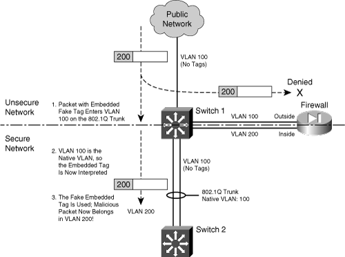
The trunk link has been configured with VLAN 100 as its native VLAN. This might have been done as an oversight, with the assumption that no other switch or host would ever connect to VLAN 100 on the inside network. However, that native VLAN is used as the springboard to get inside the secure network.
A malicious user on the outside (VLAN 100) sends a packet toward the inside. The packet is carefully crafted such that it contains an 802.1Q VLAN tag for VLAN 200—even though it is being sent over a nontrunking link that supports only a single VLAN. If the packet is a broadcast, it might be sent toward the firewall’s outside interface (also on VLAN 100) when it reaches Switch 1. The firewall examines the packet and denies it entry into the inside network, as expected.
Most likely, the packet is sent as a unicast destined for an address on the internal network. When the packet reaches Switch 1, a curious thing happens. The packet originated on VLAN 100, so the switch can forward it onto VLAN 100 of the 802.1Q trunk link. VLAN 100 is the trunk’s native VLAN, so the switch transmits the packet without adding its own VLAN tag. Now when the packet appears on the trunk link, the embedded fake tag is interpreted as an actual 802.1Q tag!
Downstream switches forward the packet based on its newly exposed VLAN 200 tag. Suddenly, the packet has “hopped” from VLAN 100 on the outside to VLAN 200 on the inside network.
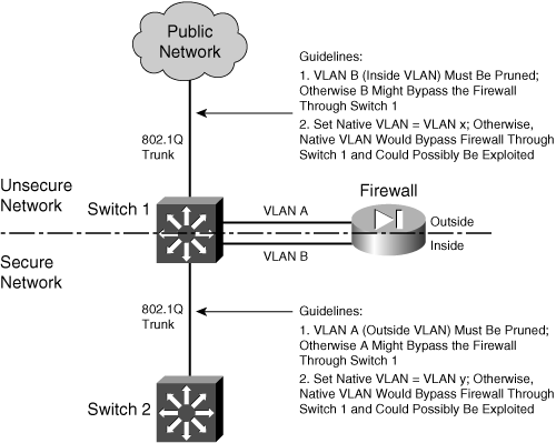
To thwart VLAN hopping, you should always carefully configure trunk links so that the native VLANs are never used to carry legitimate traffic. In other words, set a trunk’s native VLAN to an unused VLAN. In Figure 3-5, the native VLAN of the inside trunk should be set to an unused VLAN other than VLAN A, which is present on the outside, and other than VLAN B, which is present on the inside.
Trunks on opposite sides of a boundary switch should have different unused native VLANs so that the native VLAN of one side does not pass through to the native VLAN of the other side. Figure 3-6 shows this scenario. Notice that the native VLANs on the inside and outside are set to different but unused VLAN numbers.
Figure 3-6 Securing Trunk Links on a Firewall Boundary Switch
Caution
Whenever possible, you should keep the trusted and untrusted networks physically separate, carried over separate switches. Do not depend on the logical separation of VLANs within a single switch to provide inherent security. There is always a risk of misconfiguration or an exploit that would allow untrusted traffic to enter the trusted network.
Bypass Links
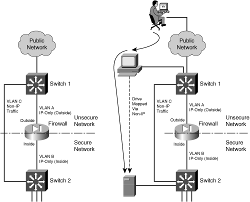
One last thing you should consider is the use of links to bypass a firewall. It might seem odd to secure a network with a firewall, only to open a path for traffic to go around it. Some environments must still connect other non-IP protocols between inside and outside networks, simply because a firewall can inspect only IP traffic. Still others might bypass IP multicast traffic to keep the firewall configuration simple.
The idea behind a bypass path is that any traffic using the path is either isolated from or incompatible with traffic passing through the firewall. In fact, you might pass some IP traffic around a firewall on a VLAN that never connects to another inside network. You might support something like a wireless LAN in your network, carried over the same switches as your secured VLANs, but where wireless users are considered “outsiders.” Then, you might pass a wireless VLAN around the firewall, with the intention that it connects only to networks outside the firewall.
Figure 3-7 shows a basic network that allows some traffic to bypass a firewall. In the left portion of the figure, IP traffic passes through the firewall while Novell IPX traffic passes around it over VLAN C. This is allowed only because some users on the outside map drives on IPX file servers on the inside.
Figure 3-7 Example of Risk When Bypassing a Firewall
Tip
At the very least, you should configure very strict IPX access lists on the Layer 3 switches at each end of the VLAN C link. If IPX traffic must be bypassed around the firewall, it should still be governed by whatever means you have available.
You should also consider using a transparent (Layer 2) firewall to handle the traffic that would otherwise flow over a link bypassing a Layer 3 firewall. For non-IP protocols, a transparent firewall can filter only according to EtherType values. However, no stateful inspection of protocols such as IPX is possible.
From a routing standpoint, IP and IPX are “ships in the night,” coexisting on switches but not intermingling. However, consider the right portion of Figure 3-7. An outside user has managed to compromise a PC that is also on the outside. This PC has a drive mapped over IPX to a secure file server. Without passing through the firewall, the outside user has managed to gain access to data on a “secure” server on the internal network.
The solution here is to be very critical of bypassing any sort of traffic around a firewall. Even if you think you have thought of every possible angle to keep internal resources isolated, there still might be a way for someone to gain access.
3-2 Configuring Routing
A firewall is a Layer 3 device, even though it inspects packets at many layers. Packets are forwarded based on their Layer 3 destination IP addresses, so the firewall must know how to reach the various destination IP networks. (This is true unless a firewall is configured for transparent firewall mode, where it operates only on Layer 2 information.)
A firewall knows about the subnets directly connected to each of its interfaces. These are shown as routes with a CONNECT (PIX 6.3) or directly connected (ASA or FWSM) identifier in output from the show route command.
To exchange packets with subnets not directly connected, a firewall needs additional routing information from one of the sources listed in Table 3-3.
Table 3-3 Routing Information Sources
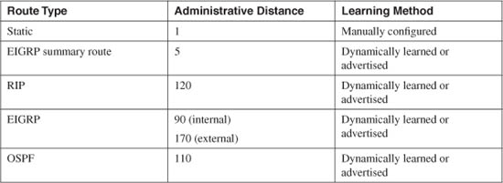
The various routing protocols go about learning and advertising route information with different techniques. Because of this, some routing protocols are generally considered more trustworthy than others. The degree of trustworthiness is given by the administrative distance, an arbitrary value from 0 to 255. Routes with a distance of 0 are the most trusted, while those with a distance of 255 are the least trusted. The default values are generally accepted and are the same as those used on routers.
Administrative distance comes in handy when the same route has been learned in multiple ways. For example, suppose the route 10.10.0.0/16 has been learned by RIP (administrative distance of 120) and OSPF (administrative distance of 110). Each of the routing protocols might come up with different next-hop addresses for the route, so which one should the firewall trust? The protocol with the lowest distance value—OSPF.
Notice from Table 3-3 that static routes have a distance of 1, which makes them more trusted than any other routing protocol. If you configure a static route, chances are you are defining the most trusted information about that route. Only directly connected routes with a distance of 0, containing the subnets configured on the firewall interfaces, are more trusted.
As soon as routes are known, packets can be forwarded to other routers or gateways that in turn forward the packets toward their destinations.
A default route is useful on the firewall’s outside interface, where the most general subnets and destination networks are located. Usually, the networks located on the inside and other higher-security interfaces are specific and well-known. Remember that the firewall has to learn about the inside networks through some means.
Using Routing Information to Prevent IP Address Spoofing
A packet’s destination address normally is used to determine how it gets forwarded. If the destination address can be found in the routing table, the firewall can forward the packet out the appropriate interface to the destination or to a next-hop router.
Packet forwarding seems straightforward, but it makes certain assumptions about a packet and its sender. For example, the address or location of a packet’s source normally is not part of the forwarding decision. That might be fine if all senders and the packets they send can be trusted implicitly. When your network is connected to a public network, full of untrusted and unknown users, however, there should be no trust at all.
A common exploit used in a denial-of-service attack involves spoofed IP addresses. A malicious user sends packets toward a target host to initiate connections or use up a resource on the target. However, the sender disguises itself by inserting a bogus source address into the packets. Either the source address does not exist, or it might be a legitimate address of some other host on some other network. The idea is to prevent any return traffic from reaching the malicious user, protecting his identity and location.
Cisco firewalls can use Reverse Path Forwarding (RPF) to detect spoofed source addresses in most cases. As soon as RPF is enabled, a firewall examines the source address of each packet arriving on an interface. It tries to find the reverse path, or the path back toward the source, in its routing table. In other words, the firewall acts as if it will send something back to the source to verify its location. If a route to the source address or network can be found, the outbound interface must match the interface where the packet originally arrived.
If a route cannot be found, or the reverse-path interface does not match the arriving interface, the packet is simply dropped, and a logging message is generated.
Normally, a firewall has specific routing information about all the IP networks on the inside or protected (nonpublic) interfaces, because those networks are known to exist and are controlled. Therefore, RPF checks to see whether packets sourced from a protected network are easily and accurately performed.
The outside or public network is a different story. The firewall usually cannot know about every IP network that exists in the outside world, so it makes do with a default route. The same is true of RPF on the outside interface. When a packet arrives on the outside interface, if the specific route to the source cannot be found, the firewall uses the default route to verify the reverse path.
You can enable RPF with the following configuration command:
Firewall(config)# ip verify reverse-path interface if_name
Notice that RPF is configured on a per-interface basis, only on the interface named if_name (inside, for example). You can repeat this command to enable RPF on multiple interfaces. Remember that RPF works by checking packets that arrive on an interface—not packets that are leaving.
Note
It might seem odd or inadvisable that the default route is used for RPF tests on the outside interface. After all, the majority of source address spoofing would probably be found on the outside public network. Unfortunately, this is mostly true, because a firewall cannot know everything about the outside network. The vast majority of IP addresses are found “somewhere out there” on the public Internet, on the outside interface.
However, RPF can detect when source addresses from the outside are spoofed with addresses that are used on an inside or protected interface. In other words, if someone tries to masquerade as a trusted user, using a trusted IP address, the firewall recognizes that the address is appearing on the wrong interface, and it drops the packet. This happens before a connection is formed and before any further access lists or stateful inspection are performed, preserving the firewall resources.
Figure 3-8 illustrates the RPF process. RPF has been enabled on the outside interface, to check packets arriving from the outside. The firewall’s routing table is shown, providing information that RPF can use about the known inside networks. The only thing known about the outside network is the default route.
Figure 3-8 Unicast RPF Operation
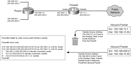
When an outside host tries to masquerade as the address 192.168.10.7, the firewall finds a matching route located on the inside network. Clearly, the outside host is spoofing that address, so the packet is dropped.
During the RPF process, each ICMP packet is examined individually. UDP and TCP packets are examined too, but only the first packet in a connection. All subsequent packets in the connection receive a quick check for the correct source interface; the route lookup and reverse path check are skipped.
You can use the following command to display RPF counters related to one or all firewall interfaces:
Firewall# show ip verify statistics [interface if_name]
For example, in the following firewall output, 3312 packets were dropped as they arrived on the inside interface because of spoofed source addresses:
Firewall# show ip verify statistics
interface outside: 170 unicast rpf drops
interface inside: 3312 unicast rpf drops
interface dmz: 3 unicast rpf drops
Firewall#
To reset the statistics counters, you can use the clear ip verify statistics command.
Configuring Static Routes
Static routes can be manually configured on a firewall. These routes are not learned or advertised; the routes you configure are the only routes the firewall knows unless a routing protocol is also being used.
The firewall uses static routing information, as shown in Figure 3-9.
Figure 3-9 Static Routes Used by a Firewall
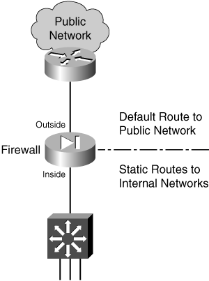
You can define static routes by following these configuration steps:
1. Define a static route to a specific subnet:
Firewall(config)# route if_name ip_address netmask gateway_ip [distance]
The IP subnet defined by ip_address and netmask (a standard dotted-decimal subnet mask) can be reached by forwarding packets out the firewall interface named if_name (inside or outside, for example). The packets are forwarded to the next-hop gateway at IP address gateway_ip.
By default, a static route receives an administrative distance of 1. You can override this behavior by specifying a distance value (1 to 255).
Tip
You can also define the static route with the firewall’s own interface IP address as the gateway address. If the next-hop gateway address is not known or if it is subject to change, you can simply have the firewall use the interface where the gateway is connected.
When packets are forwarded toward the gateway, the firewall sends ARP requests for the destination address. The next-hop router must be configured to use proxy ARP so that it responds with its own MAC address as the destination.
This is not a recommended approach, however. You should use it only in cases where the next-hop router is subject to change or is unknown. Proxy ARP is generally considered a risk, because it exposes a firewall to memory exhaustion during certain types of denial-of-service attacks.
If you have configured IPv6 operation on a firewall, you can also configure static IPv6 routes. The command syntax is very similar to the IPv4 form:
Firewall(config)# ipv6 route if_name ipv6_prefix/prefix_length
ipv6_gateway [distance]
2. Define a default static route:
Firewall(config)# route if_name 0.0.0.0 0.0.0.0 gateway_ip [distance]
You can define a default route so that the firewall knows how to reach any network other than those specifically defined or learned. The default network and subnet mask are written as 0.0.0.0 0.0.0.0 to represent any address. They can also be given more simply as 0 0 to save typing.
The firewall assumes that the next-hop router or gateway at IP address gateway_ip knows how to reach the destination. You can configure up to three different default routes on a firewall. If more than one default route exists, the firewall distributes outbound traffic across the default route gateways to load balance the traffic.
You can remove a static route by repeating this command beginning with the no keyword.
Tip
You can verify a firewall’s routing information by using the show route EXEC command. The output shows routes learned by any possible means, whether directly connected, static, or through a dynamic routing protocol.
Static routes are shown as routes with an OTHER static identifier in output from the PIX 6.3 show route command, or with an S identifier in the ASA or FWSM show route command. For example, the default route in the following output has been configured as a static route:
Firewall# show route
O IA 192.168.167.1 255.255.255.255
[110/11] via 192.168.198.4, 82:39:36, inside
C 192.168.198.0 255.255.255.0 is directly connected, inside
C 128.163.93.128 255.255.255.128 is directly connected, outside
S* 0.0.0.0 0.0.0.0 [1/0] via 128.163.93.129, outside
Firewall#
Static routes and routes learned from a routing protocol are shown with square brackets containing two values. The first value is the administrative distance, and the second value is the metric derived or used by the routing protocol. For example, the OSPF route to 192.168.167.1 has [110/11]—OSPF uses administrative distance 110, while this specific route has an OSPF metric of 11.
Static Route Example
The following static routes are to be configured on a firewall:
• A default route points to gateway 192.168.1.1 on the outside interface.
• Network 172.21.0.0/16 can be found through gateway 192.168.254.2 on the inside interface.
• Network 172.30.146.0/24 can be found through gateway 192.168.254.10, also on the inside interface.
The static route configurations are as follows:
Firewall(config)# route outside 0.0.0.0 0.0.0.0 192.168.1.1 1
Firewall(config)# route inside 172.21.0.0 255.255.0.0 192.168.254.2 1
Firewall(config)# route inside 172.30.146.0 255.255.255.0 192.168.254.10 1
Favoring Static Routes Based on Reachability
Normally, if a static route is configured, it stays active until it is manually removed. A static route is simply an unchanging definition of a next-hop destination—regardless of whether that destination is reachable. If a single ISP is the sole means of reaching the outside world, a static default route works nicely to point all outbound traffic to the ISP’s gateway address.
Suppose you had connections to two ISPs; one might be favored over the other, but the default routes to each ISP are equally weighted. In other words, the firewall tries to balance the outbound traffic equally across the connections. Even if the connection to one ISP goes down, the firewall still uses the static route that points to that ISP—effectively sending some outbound traffic into a black hole.
Beginning with ASA 7.2(1), a static route can be conditional. So, if a target address is reachable, the static route remains active; if the target is not reachable, the static route becomes inactive. This allows you to configure multiple static or default routes without worrying about whether one ISP connection is working or not.
To do this, you configure a service level agreement (SLA) monitor process that monitors an arbitrary target address. That process is associated with a static route so that the route tracks the reachability of the target. Use the following steps to configure static address tracking:
1. Define the SLA monitor process:
Firewall(config)# sla monitor sla-id
The process is known by its sla-id, an arbitrary number from 1 to 2,147,483,647.
2. Define the reachability test:
Firewall(config-sla-monitor)# type echo protocol ipIcmpEcho target interface if-name
The only test type is echo, which sends ICMP echo request packets to the target IP address found on firewall interface if-name.
You should select a target address that is a reliable indicator of a route’s reachability. For example, you could use an ISP’s next-hop gateway address as a target to test the ISP connection’s reachability. The target address can be another router, firewall, host, and so on.
Tip
Before you configure the ICMP echo target address, you might want to manually test the target’s reachability with the ping target command.
a. (Optional) Set the test frequency:
Firewall(config-sla-monitor-echo)# frequency seconds
By default, echo tests are run every 60 seconds. You can set a different time interval as seconds (1 to 604,800 seconds or 7 days).
b. (Optional) Set the number of ICMP echo packets to send:
Firewall(config-sla-monitor-echo)# num-packets number
By default, only one ICMP request packet is sent during an echo test. You can define a different number of packets as number (1 to 100).
c. (Optional) Set the payload size of the ICMP request:
Firewall(config-sla-monitor-echo)# request-data-size bytes
By default, each ICMP echo request packet has a payload of 28 bytes. You can set the payload size as bytes (0 to 16,384 bytes), although you cannot use a value less than 28. As well, you should not choose a payload size that makes the ICMP echo request packet larger than the path MTU.
d. (Optional) Set the type of service (TOS) value:
Firewall(config-sla-monitor-echo)# tos number
By default, each ICMP echo request packet sent has an IP TOS value of 0. You can choose a different value as number (0 to 255). This option can be handy if other routers along the path to the target are configured to enforce quality of service (QoS) policies based on the TOS byte in the IP packet headers.
e. (Optional) Set the timeout interval:
Firewall(config-sla-monitor-echo)# timeout milliseconds
By default, the firewall waits 5000 ms (5 seconds) to receive an ICMP echo reply packet in response to its echo test. If a reply packet is received within the timeout interval, the target is reachable. If not, the target is assumed to be unreachable, and the echo test fails.
You can choose a different timeout interval as milliseconds (0 to 604,000,000 milliseconds, or 7 days). The timeout interval must be longer than the frequency defined with the frequency command.
f. (Optional) Set the test threshold:
Firewall(config-sla-monitor-echo)# threshold milliseconds
The firewall also keeps track of a test threshold, which is used as an indicator that the target is getting increasingly hard to reach. The threshold is not used to decide whether the target is reachable. Instead, it can give you an idea of how realistic your choice of the timeout interval is.
By default, the threshold interval is set to 5000 ms (5 seconds). You can set a different threshold value as milliseconds (0 to 2,147,483,647 ms). Keep in mind that the threshold value must always be less than or equal to the timeout interval value.
For example, suppose you choose a timeout interval of 10,000 ms (10 seconds) and a threshold value of 5000 ms. After many echo tests are run, you can look at the test statistics to see how often the threshold is exceeded. If it is rarely exceeded, you might decide to reduce the timeout value to something at or below the current threshold value. If you decide to reduce the timeout value, you should also reduce the threshold value.
3. Schedule the SLA monitor test:
Firewall(config)# sla monitor schedule sla-id [life {forever | seconds}] [start-time
{hh:mm[:ss] [month day | day month] | pending | now | after hh:mm:ss}] [ageout seconds]
[recurring]
The test can begin in one of the following ways:
You can specify the lifetime of the test with the life keyword, followed by forever (infinite lifetime) or seconds. By default, a test runs for 3600 seconds or 1 hour.
For continuing reachability tests, you should use the following command syntax:
Firewall(config)# sla monitor sla-id life forever now
The test continues to run until you manually remove it from the firewall configuration with the no sla monitor sla-id command.
4. Enable reachability tracking:
Firewall(config)# track track-id rtr sla-id reachability
The SLA monitor test identified by sla-id is used to track reachability information. Each track process is known by its track-id index, an arbitrary value from 1 to 500. You should define a unique track index for each SLA monitor test that you configure, so that each test can be tracked independently.
5. Apply tracking to a static route:
Firewall(config)# route if_name ip_address netmask gateway_ip [distance] track
track-id
The normal static route command syntax is used, along with the track keyword. Track process number track-id is used to provide reachability information for the static route. If the test target is reachable (it returns ICMP echo replies as expected), the static route remains active in the routing table.
If the target is not reachable (ICMP echo replies are not received as expected), the static route remains in the running configuration, but is not active in the routing table.
6. Monitor static route tracking:
You can monitor the status of a tracking process with any of the following EXEC commands:
Firewall# show track
Firewall# show route
Firewall# debug track
Firewall# debug sla monitor trace
Reachable Static Route Example
A firewall has two paths to the outside Internet, using two independent ISPs, as shown in Figure 3-10. The firewall can be configured with two default routes that point to the two ISP routers, 10.1.1.100 and 10.1.1.200. Outbound traffic toward the Internet is balanced across the two default routes, and across the two ISPs.
Figure 3-10 An Example Network Using Reachability Information
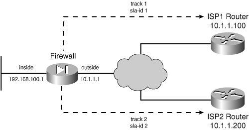
The firewall is also configured to track the reachability of each ISP, so that the appropriate static route can be deactivated if an ISP connection is down. SLA monitor test 1 is configured to perform echo tests on the ISP1 router at 10.1.1.100, while SLA test 2 checks the ISP2 router at 10.1.1.200. The following commands can be used to configure the reachability tests and static routes:
Firewall(config)# sla monitor 1
Firewall(config-sla-monitor)# type echo protocol ipIcmpEcho 10.1.1.100 interface outside
Firewall(config-sla-monitor-echo)# frequency 30
Firewall(config-sla-monitor-echo)# threshold 1000
Firewall(config-sla-monitor-echo)# timeout 3000
Firewall(config-sla-monitor-echo)# exit
Firewall(config-sla-monitor)# exit
Firewall(config)# sla monitor schedule 1 life forever now
!
Firewall(config)# track 1 rtr 1 reachability
!
Firewall(config)# sla monitor 2
Firewall(config-sla-monitor)# type echo protocol ipIcmpEcho 10.1.1.200 interface outside
Firewall(config-sla-monitor-echo)# frequency 30
Firewall(config-sla-monitor-echo)# threshold 1000
Firewall(config-sla-monitor-echo)# timeout 3000
Firewall(config-sla-monitor-echo)# exit
Firewall(config-sla-monitor)# exit
Firewall(config)# sla monitor schedule 2 life forever now
!
Firewall(config)# track 2 rtr 2 reachability
!
Firewall(config)# route 0.0.0.0 0.0.0.0 10.1.1.100 track 1
Firewall(config)# route 0.0.0.0 0.0.0.0 10.1.1.200 track 2
Notice that each static route uses a different tracking process. That means either static route can be deactivated depending on the status of its respective next-hop router. Static route tracking is a rather silent process, and the firewall will not give you any obvious signs that it is actually testing the reachability.
To see this in action, you can use the show route command to display the current routing table contents. If both ISP router targets are reachable, then both static routes are shown, as in the following output:
Firewall# show route
Codes: C - connected, S - static, I - IGRP, R - RIP, M - mobile, B - BGP
D - EIGRP, EX - EIGRP external, O - OSPF, IA - OSPF inter area
N1 - OSPF NSSA external type 1, N2 - OSPF NSSA external type 2
E1 - OSPF external type 1, E2 - OSPF external type 2, E - EGP
i - IS-IS, L1 - IS-IS level-1, L2 - IS-IS level-2, ia - IS-IS inter area
* - candidate default, U - per-user static route, o - ODR
P - periodic downloaded static route
Gateway of last resort is 10.1.1.100 to network 0.0.0.0
C 127.0.0.0 255.255.0.0 is directly connected, cplane
C 192.168.100.0 255.255.255.0 is directly connected, inside
S* 0.0.0.0 0.0.0.0 [1/0] via 10.1.1.100, outside
[1/0] via 10.1.1.200, outside
Here, both static routes are listed, although no indication that they are conditional is listed. You can always confirm the static route configuration with the show run route command:
Firewall# show run route
route outside 0.0.0.0 0.0.0.0 10.1.1.100 track 1
route outside 0.0.0.0 0.0.0.0 10.1.1.200 track 2
Firewall#
You can also see the current status of a track process with the show track [track-id] command:
Firewall# show track 1
Track 1
Response Time Reporter 1 reachability
Reachability is Up
1 change, last change 00:01:03
Latest operation return code: OK
Latest RTT (millisecs) 1
Tracked by:
STATIC-IP-ROUTING 0
Firewall#
You can also enable debugging output for the tracking process. Use the debug sla monitor trace command to get some real-time indication of SLA probes as they are sent. However, to see messages indicating a change in reachability, you can use the debug track command, as in the example that follows. After each reachability change is announced, the routing table is shown for clarity. Notice how the static route to ISP2 is missing after track process 2 announces that the target is unreachable, and how the static route returns when the target comes up again.
Firewall# debug track
Firewall#
Firewall#
Firewall# Track: 2 Change #1 rtr 2, reachability Up->Down
Firewall# show route
Codes: C - connected, S - static, I - IGRP, R - RIP, M - mobile, B - BGP
D - EIGRP, EX - EIGRP external, O - OSPF, IA - OSPF inter area
N1 - OSPF NSSA external type 1, N2 - OSPF NSSA external type 2
E1 - OSPF external type 1, E2 - OSPF external type 2, E - EGP
i - IS-IS, L1 - IS-IS level-1, L2 - IS-IS level-2, ia - IS-IS inter area
* - candidate default, U - per-user static route, o - ODR
P - periodic downloaded static route
Gateway of last resort is 10.1.1.100 to network 0.0.0.0
C 127.0.0.0 255.255.0.0 is directly connected, cplane
C 192.168.100.0 255.255.255.0 is directly connected, inside
S* 0.0.0.0 0.0.0.0 [1/0] via 10.1.1.100, outside
Firewall#
Firewall#
Firewall# Track: 2 Change #2 rtr 2, reachability Down->Up
Firewall#
Firewall# show route
Codes: C - connected, S - static, I - IGRP, R - RIP, M - mobile, B - BGP
D - EIGRP, EX - EIGRP external, O - OSPF, IA - OSPF inter area
N1 - OSPF NSSA external type 1, N2 - OSPF NSSA external type 2
E1 - OSPF external type 1, E2 - OSPF external type 2, E - EGP
i - IS-IS, L1 - IS-IS level-1, L2 - IS-IS level-2, ia - IS-IS inter area
* - candidate default, U - per-user static route, o - ODR
P - periodic downloaded static route
Gateway of last resort is 10.1.1.100 to network 0.0.0.0
C 127.0.0.0 255.255.0.0 is directly connected, cplane
C 192.168.100.0 255.255.255.0 is directly connected, inside
S* 0.0.0.0 0.0.0.0 [1/0] via 10.1.1.100, outside
[1/0] via 10.1.1.200, outside
Firewall#
Configuring RIP to Exchange Routing Information
Cisco firewalls can passively listen to RIP updates (either version 1 or 2) to learn routing information. Routing advertisements from the firewall are limited to one type—a firewall interface as a default route. RIP can be used in either of the following versions:
• RIP version 1, which supports only classful networks. Advertisements are broadcast unencrypted.
• RIP version 2, which supports classless networks. Advertisements can be authenticated by a cryptographic function for security purposes.
RIP routing information is used by the firewall as shown in Figure 3-11.
Figure 3-11 Firewall Using RIP for Routing Information
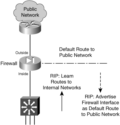
You can configure RIP on a firewall by following these configuration steps:
1. Passively listen to RIP updates from other routers.
a. Listen to RIP version 1 updates:
Firewall(config)# rip if_name passive [version 1]
Any networks advertised in RIPv1 updates received on the firewall interface named if_name are added to the routing table. To protect information about the internal networks, the firewall does not advertise any routes to its internal or protected networks.
b. Listen to RIP version 2 updates:
Firewall(config)# rip if_name passive version 2 [authentication
[text | md5 key (key_id)]]
Any networks advertised in RIPv2 updates received on the firewall interface named if_name are added to the routing table.
If RIPv2 authentication is being used by other routers, the firewall must use the same method. Advertisements can be authenticated with a cleartext text key (up to a 16-character text string) that is passed within the routing update. Naturally, having the authentication key pass across the network in the clear (unencrypted) is not very secure.
You can also use message digest 5 (MD5) authentication. An md5 key (up to a 16-character text string) can be defined on each router. The key is not sent as a part of the routing updates. Instead, it is kept hidden and is used only to validate the MD5 hash value that is computed on each routing advertisement and the key. MD5 also supports multiple keys, referenced by a key_id (1 to 255). Both the key ID and the key itself must match between neighboring RIPv2 routers.
2. Advertise a firewall interface as a default route:
Firewall(config)# rip if_name default version [1 | 2] [authentication
[text | md5 key key_id]]
The only route that a firewall can advertise is a default route, with its own interface named if_name as the gateway address. The default route is advertised using RIP version 1 or 2. An optional authentication can be used with RIPv2, as a cleartext text key or an md5 key.
Tip
You can verify the RIP configuration commands that have been entered with the show rip [if_name] (PIX 6.3) or show running-config rip (ASA or FWSM) EXEC command.
To see RIP update activity, you can also use the debug rip command. In the following example, the firewall has received one route advertisement:
%PIX-7-711001: RIP: received packet from interface inside [pif=2]
(192.168.198.4:520)
%PIX-7-711001: RIP: interface inside received v2 update from 192.168.198.4
%PIX-7-711001: RIP: update contains 1 routes
%PIX-7-711001: RIP: Advertise network 192.168.167.0 mask 255.255.255.0
gateway 192.168.198.4 metric 1
If RIP routes do not appear in the routing table as expected, there could be a misconfiguration involving RIPv2 authentication. In this case, the debug output would show a message like this:
%PIX-1-107001: RIP auth failed from 192.168.198.4: version=2, type=ffff,
mode=3, sequence=13 on interface inside
You can also display the current routing table to see routes that RIP has learned. Those entries are marked with an R indicator, as in the following example:
Firewall# show route
S 0.0.0.0 0.0.0.0 [1/0] via 128.163.93.129, outside
C 128.163.93.128 255.255.255.128 is directly connected, outside
R 192.168.167.0 255.255.255.0 [1/0] via 192.168.198.4, inside
C 192.168.198.0 255.255.255.0 is directly connected, inside
Firewall#
RIP Example
A firewall is to use RIP version 2 to learn routing information on its inside interface. The firewall also advertises its inside interface as the default gateway. MD5 authentication is being used on other internal RIPv2 routers, using key number 1, mysecretkey. The configuration is as follows:
Firewall(config)# rip inside passive version 2 authentication md5 mysecretkey 1
Firewall(config)# rip inside default version 2 authentication md5 mysecretkey 1
Configuring EIGRP to Exchange Routing Information
The Enhanced Interior Gateway Routing Protocol (EIGRP) is new to ASA 8.0. As its name implies, EIGRP is based on Interior Gateway Routing Protocol (IGRP), but with many enhancements. EIGRP is a distance vector routing protocol, and its routing metrics are based on a combination of delay, bandwidth, reliability, load, and MTU.
EIGRP uses a neighbor discovery mechanism that works by sending “hello” messages to directly connected neighboring routers. Neighbors can be dynamically discovered or statically configured. All EIGRP messages, including the hello protocol, are sent as multicast packets to address 224.0.0.10, the all EIGRP routers address, using IP protocol 88.
EIGRP supports variable-length subnet masks (VLSM) and route summarization, providing plenty of flexibility in its routing information. It also uses the Diffusing Update Algorithm (DUAL) to compute and maintain routing information from all of its neighbors. The ASA (or any other EIGRP router) always uses a feasible successor, or a neighboring router with the lowest cost path to a destination.
EIGRP routers do not send periodic routing updates. Rather, routing information is exchanged only when a route’s metric changes, based on information from neighboring routers. If you have routers running EIGRP in your network, you might want to run EIGRP on your ASA, too, so that the ASA can benefit from dynamic routing information. You can use the following steps to configure EIGRP; if you are familiar with configuring EIGRP on a Cisco router, you should find that the ASA commands are identical.
1. Enable an EIGRP process:
Firewall(config)# router eigrp as-num
EIGRP routers can exchange routing information if they each belong to the same autonomous system. You can define the autonomous system number as as-num, a number from 1 to 65535. Make sure the autonomous system number matches that of other EIGRP routers in your network.
2. Associate a network with the EIGRP process:
asa(config-router)# network ip-addr [mask]
EIGRP must know which interfaces are to participate in routing updates and which interface subnets to advertise. If an interface address falls within the subnet ip-addr and mask, then EIGRP uses it in its operation.
If you want the interface subnet to be advertised, but you do not want the interface to participate in EIGRP routing exchanges, you can use the following command:
asa(config-router)# passive-interface if_name
3. (Optional) Use stub routing for a firewall with a single exit point:
asa(config-router)# eigrp stub {receive-only | [connected] [redistributed] [static]
[summary]}
If the firewall has a single connection to the outside world through a distribution router, it can become an EIGRP stub router. As a stub, it can receive routes (usually a default route) from its neighbor, but advertises only specific routes of its own.
With the receive-only keyword, the firewall receives updates but does not advertise anything. Otherwise, you can specify one or more route types to advertise. Use the connected keyword to advertise routes that are directly connected to the firewall, the redistributed keyword to advertise any routes that the firewall has redistributed into its EIGRP process, the static keyword to advertise static routes defined on the firewall, or the summary keyword to advertise summary addresses defined on the firewall.
4. (Optional) Define a specific EIGRP neighbor:
Normally, the firewall discovers other EIGRP neighbors by exchanging multicast hello messages. If a neighbor is located across a network that does not support multicast traffic, you can statically define the neighbor. At that point, the firewall communicates with the neighbor via unicast traffic. Use the following EIGRP configuration command to define a neighbor:
asa(config-router)# neighbor ip-addr interface if_name
The neighbor is located at ip-addr over the specified interface.
5. (Optional) Filter EIGRP updates to suppress specific networks:
asa(config-router)# distribute-list acl {in | out} [interface if_name]
Routes or subnets that are permitted by access list acl are filtered from EIGRP updates. The in keyword filters the routes as they are received from other EIGRP routers, while the out keyword filters the routes in EIGRP advertisements from the firewall.
You can use the interface keyword to filter routes on a specific interface.
6. (Optional) Control route summarization:
By default, EIGRP automatically summarizes subnet routes into classful network routes when they are advertised. If you have contiguous subnets that are separated among firewall interfaces or across EIGRP routers, you should disable route summarization with the following EIGRP configuration command:
asa(config-router)# no auto-summary
Otherwise, you can configure a summary address that is advertised on an interface. This can be handy if you need a summary address that does not fall cleanly within a network boundary. In addition, if you have already disabled automatic summarization, the firewall can still advertise a summary address that is manually configured. You can configure a summary address with the following commands:
asa(config)# interface if_name
asa(config-if)# summary-address eigrp as-num address mask [distance]
The summary address given by address mask is advertised by EIGRP autonomous system number as-num. You can specify an administrative distance to override the default value of 5 for summary addresses.
7. (Optional) Redistribute routing information from other sources:
If the firewall is running other routing protocols like RIP or OSPF, you can redistribute routes learned from those methods into EIGRP. First, you should configure a route map to filter routing information from one routing protocol into EIGRP.
You can define a default metric for all routes that are redistributed into EIGRP, because metrics from the different route sources are not equivalent. Use the following EIGRP configuration command:
asa(config-router)# default-metric bandwidth delay reliability loading mtu
Specify the composite default metric as the combination of bandwidth (1 to 4294967295 kbps), delay (1 to 4294967295 in tens of microseconds), reliability (0 to 255, ranging from low to high), loading (1 to 255, ranging from low to high link usage), and mtu (1 to 65535 bytes).
If a default metric is not defined, you can configure a metric as a part of route redistribution.
To redistribute routes that were learned by RIP, were statically defined, or are directly connected, use the following EIGRP configuration command:
asa(config-router)# redistribute {rip | static | connected} [metric bandwidth delay
reliability load mtu] [route-map map_name]
To redistribute routes learned from OSPF, use the following EIGRP configuration command:
asa(config-router)# redistribute ospf pid [match {internal | external [1 | 2] | nssa-
external [1 | 2]}] [metric bandwidth delay reliability load mtu] [route-map map_name]
Identify the OSPF process as pid. You can match against OSPF internal, type 1 or 2 OSPF external, or external type 1 or 2 Not So Stubby Area (nssa-external) routes.
8. (Optional) Secure EIGRP updates with neighbor authentication:
asa(config)# interface if_name
asa(config-if)# authentication mode eigrp as-num md5
asa(config-if)# authentication key eigrp as-num key-string key-id key-id
The ASA can use the MD5 hash algorithm to verify a neighbor router’s authentication key. Define the ASA’s key as the text string key-string, also known as key number key-id (a number from 1 to 255). As soon as authentication is enabled, any EIGRP neighbors that fail to present the correct key are ignored.
9. (Optional) Adjust EIGRP timers:
By default, the firewall sends hello messages every 5 seconds and expects neighbors to hold its neighbor state if they do not receive its hello messages for 15 seconds before they consider it to be unreachable. You should adjust these timers to match the values used by neighboring routers, only if those routers are not using the default values. You can use the following interface configuration commands to adjust the timers for EIGRP autonomous system number as-num:
asa(config)# interface if_name
asa(config-if)# hello-interval eigrp as-num seconds
asa(config-if)# hold-time eigrp as-num seconds
10. (Optional) Adjust the interface delay used in EIGRP metric calculations:
Each firewall interface has a delay value that is used in EIGRP metric calculations. By default, the delay is set to a value that is inversely proportional to the bandwidth of the interface. You can display the current delay value with the show interface command, as in the following example:
Firewall# show interface
Interface GigabitEthernet0/0 "outside", is up, line protocol is up
Hardware is i82546GB rev03, BW 1000 Mbps, DLY 1000 usec
Auto-Duplex(Full-duplex), Auto-Speed(100 Mbps)
You can adjust the delay value with the following interface configuration command:
asa(config)# interface if_name
asa(config-if)# delay value
An EIGRP Configuration Example
A firewall is positioned so that its interface ethernet0/1 faces the outside public network, while ethernet0/0 faces the inside protected network. EIGRP is being used on the internal network, because of the network’s size. The firewall participates in EIGRP so that it can receive dynamic updates about internal IP subnets.
Because the firewall has only a single path to the outside world, it can become an EIGRP stub router. Also, the outside interface does not need to participate in routing updates because no trusted EIGRP neighbor exists there.
You can use the following configuration commands to set up EIGRP on the firewall:
Firewall(config)# router eigrp 101
Firewall(config-router)# network 10.0.0.0
Firewall(config-router)# network 192.168.1.0
Firewall(config-router)# eigrp stub
Firewall(config-router)# passive-interface ethernet0/1
Firewall(config-router)# exit
Firewall(config)# route outside 0.0.0.0 0.0.0.0 10.0.1.2 1
!
Firewall(config)# interface ethernet 0/1
Firewall(config-if)# nameif outside
Firewall(config-if)# security-level 0
Firewall(config-if)# ip address 10.0.1.1 255.255.255.0
Firewall(config-if)# exit
!
Firewall(config)# interface ethernet 0/0
Firewall(config-if)# nameif inside
Firewall(config-if)# security-level 100
Firewall(config-if)# ip address 192.168.1.1 255.255.255.0
Firewall(config-if)# authentication mode eigrp 101 md5
Firewall(config-if)# authentication key eigrp 101 secret123 key-id 1
Firewall(config-if)# exit
Configuring OSPF to Exchange Routing Information
OSPF is a link-state routing protocol. The routing domain is partitioned into areas. Area 0 is always considered the backbone area of the OSPF domain or autonomous system.
When an OSPF router connects to two or more different areas, it is called an Area Border Router (ABR). When an OSPF router connects an area to a non-OSPF domain and it imports routing information from other sources into OSPF, it is called an Autonomous System Boundary Router (ASBR).
OSPF routers build a common database of the status of all links in the area by exchanging link-state advertisements (LSA). The routers build their routing tables by computing the shortest path first (SPF) algorithm based on that database.
OSPF Routing Scenarios with a Firewall
When a firewall is configured to use OSPF, consider its role in the scenarios described in the following sections.
OSPF Used Only on the Inside
The firewall becomes an ASBR, bordering an OSPF area with a non-OSPF public network. Figure 3-12 shows this topology.
Figure 3-12 Using OSPF Only on the Inside of the Firewall
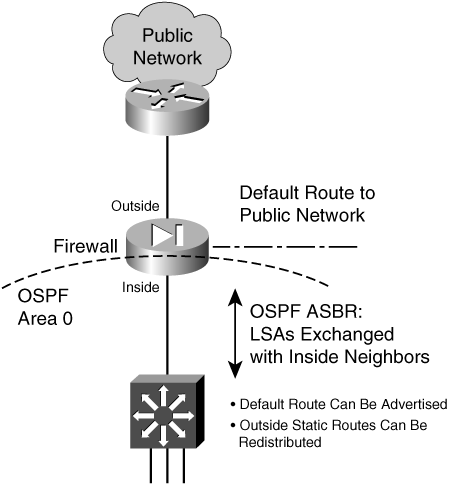
On the outside, only static routes can be configured. On the inside, OSPF LSAs are exchanged with other neighboring routers. The static routes to outside destinations can be redistributed into OSPF so that they are advertised within the inside area. There is no danger or possibility that the firewall will advertise inside to the outside (unsecure) world.
OSPF Used Only on the Outside
The firewall is an ASBR, bordering an OSPF area on the outside with a non-OSPF inside network. Figure 3-13 shows this topology.
Figure 3-13 Using OSPF Only on the Outside of the Firewall
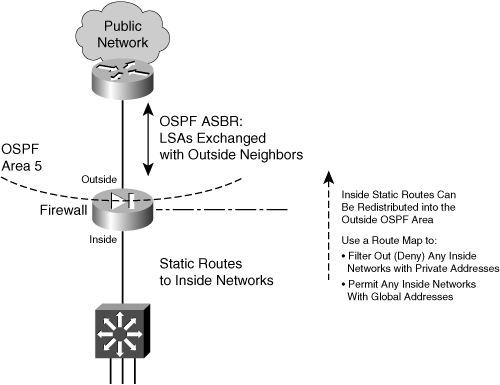
On the inside, only static routes can be configured. On the outside, OSPF LSAs are exchanged with other neighboring routers. The static routes to inside networks can be redistributed to the outside area. If you need to do that, you should carefully consider filtering the information so that no inside network details are revealed to the outside. As well, if NAT is being used at the outside firewall interface, it does not make sense to advertise inside private IP subnets.
To filter redistributed routes toward the outside, you should configure a route map on the firewall. Be sure to deny any internal network addresses and permit any global or public network addresses.
OSPF Used on Both Sides of the Firewall (Same Autonomous System)
Here, the firewall is an ABR because it borders an OSPF area with the OSPF backbone area. Because both areas are within the same autonomous system (AS), the firewall is positioned more like a traditional ABR. This situation might be needed if your organization maintains the inside and outside networks (except for the public Internet) and the firewall protects only a subset of the whole AS. Figure 3-14 shows this topology.
Figure 3-14 Using OSPF on Both Sides of the Firewall (ABR)
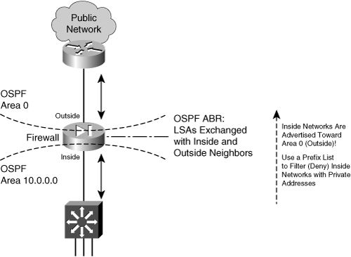
On the inside, the firewall exchanges OSPF LSAs with other inside routers in that area. On the outside, the firewall exchanges LSAs with other corporate routers in the OSPF backbone area. This topology makes it easy to maintain dynamic routing information on the routers and the firewall for a large network.
Routes from the OSPF backbone (outside) are advertised toward the inside area. This poses no real problem, because the outside networks are less secure and are expected to be known. The firewall also advertises inside routes toward the backbone area (outside).
To filter routes that are advertised toward the backbone area, you should configure a prefix list on the firewall. Be sure to deny any internal networks with private IP addresses and permit any others that should be known to the outside. (A prefix list is needed because the inside routes are not redistributed to the outside; rather, they are simply advertised within OSPF.)
OSPF Used on Both Sides of the Firewall (Different Autonomous Systems)
This is a unique case, because the firewall separates two distinct autonomous systems, each with its own OSPF backbone area. Now the firewall must become an ASBR for both the inside and the outside. In other words, two separate OSPF processes must run, each supporting a different AS (inside and outside). Figure 3-15 shows this topology.
Figure 3-15 Using OSPF on Both Sides of the Firewall (ASBR)
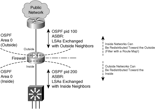
A Cisco firewall can run up to two unique OSPF processes, which makes this scenario possible. Each one runs under a different process ID or number. On the outside, LSAs are exchanged with other neighboring routers. On the inside, a different set of LSAs is exchanged with internal neighbors. By default, no routing information is advertised from the inside to the outside, and vice versa.
You can configure one OSPF process to redistribute routes from another OSPF process; however, for example, the inside process can redistribute routes from the outside process. This is usually acceptable because public routes can be freely advertised and used.
You can also redistribute routes from the inside process into the outside process. If that is necessary, you should configure a route map to filter any internal routing information that should not become public knowledge. Be sure to deny any internal networks with private IP addresses and permit others that should be known to the outside.
Configuring OSPF
OSPF is a complex, robust routing protocol. This also means that it is very flexible but can be tedious to configure. You should be well acquainted with OSPF as an advanced IP routing topic before you attempt to configure and use it on a firewall; however, do not be overwhelmed by the number of configuration command possibilities. Instead, try to configure OSPF according to other existing routers in your network. Break it into these basic functions:
• Configure the OSPF process. Define networks and areas.
• Configure authentication if needed.
• Configure a prefix list if the firewall will be an ABR.
• Configure summary routes, and tune OSPF only if you feel comfortable doing this.
• Configure route redistribution only if you need to inject routes from one side of the firewall to another.
In very large or complex network topologies, the firewall might connect to an OSPF stub or Not So Stubby Area (NSSA). The firewall might also be involved in a virtual link. If these situations apply, you can work through those configuration steps, too.
The configuration commands needed for each of the OSPF functions are presented in the following list. Follow them in order, skipping over the ones that are obviously not needed in your network scenario.
1. Define an OSPF process:
Firewall(config)# router ospf pid
The OSPF process is identified by its process ID pid (an arbitrary number from 1 to 65535). Up to two separate OSPF processes can be run on a firewall. This allows each process to exchange routing information independently, although a single routing table is maintained in the firewall. (The process ID is only locally significant; it is not passed or matched among routers and firewalls.)
2. (Optional) Uniquely identify the OSPF router ID:
Firewall(config-router)# router-id ip_address
By default, OSPF uses the numerically highest IP address defined on any firewall interface as the router ID. For example, an interface with IP address 192.168.1.2 is considered to be higher than one that uses 10.1.1.1 or even 192.168.1.1. This value identifies the “router” in any OSPF exchanges with its neighbors.
If the highest address on your firewall is a private address (172.28.4.1, for example), you might not want to divulge the private network information to other parties. In this case, you can configure the firewall to use an interface that has a global or public IP address ip_address.
3. (Optional) Generate logging messages when OSPF neighbor states change:
Firewall(config-router)# log-adj-changes [detail]
By default, the firewall generates logging messages to indicate when an OSPF neighbor adjacency goes up or down. In other words, the log-adj-changes command is present in the configuration by default.
You can add the detail keyword to generate logging messages for each OSPF neighbor state change, not just for neighbor up and down states. To disable adjacency logging, you can precede the command with the no keyword.
For example, when adjacency logging is enabled, messages similar to the following are generated:
%ASA-5-503001: Process 1, Nbr 192.168.167.1 on inside from FULL to DOWN,
Neighbor Down: Dead timer expired
4. Assign and activate a network to an OSPF area:
Firewall(config-router)# network ip_address netmask area area_id
The OSPF process exchanges routing information on any firewall interface that falls within the address range specified here. As well, the network assigned to that interface is advertised by OSPF.
The range of addresses is defined by ip_address and netmask (a normal dotted-decimal subnet mask, not a wildcard mask as in IOS). If an interface subnet falls within that range, it is also assigned to OSPF area area_id (a decimal number 0 to 4294967295, or an IP subnet written in dotted-decimal format).
Tip
An OSPF area can be referred to by a decimal number or by a subnet notation. This is possible because the area number is stored as one 32-bit number (0 to 4294967295). You might also think of the area as always having a subnet notation—a decimal area number is always preceded by three octets of 0s. For example, area 5 can also be written as 0.0.0.5, area 100 is 0.0.0.100, and area 0 is 0.0.0.0. Using subnet notation for OSPF areas is handy when you have a specific subnet by itself in one area.
Also remember that OSPF must have one backbone area, called area 0 or area 0.0.0.0.
5. (Optional) Authenticate OSPF exchanges with other neighbors in an area:
Firewall(config-router)# area area_id authentication [message-digest]
OSPF peers can authenticate information from each other using cleartext passwords (by default) or MD5 (with the message-digest keyword). If authentication is enabled on one device, it must be enabled on all the neighboring devices in the same area.
In addition, the actual authentication keys are defined on each OSPF interface. This is done in Step 12b.
6. (Optional; ABR only) Keep the private network from being advertised to an outside area.
If a firewall is configured as an ABR, it sends type 3 LSAs between the areas it touches. This means that the networks in each area are advertised into other areas. Naturally, you would not want private networks to be advertised toward the outside for security and network translation reasons.
a. Define a prefix list for filtering routes:
Firewall(config)# prefix-list list_name [seq seq_number] {permit | deny}
prefix/len [ge min_value] [le max_value]
The prefix list named list_name (an arbitrary text string) is defined for filtering routes. You can repeat this command to add more conditions to the list. By default, prefix list entries are automatically numbered in increments of 5, beginning with sequence number 5. Match entries are evaluated in sequence, starting with the lowest defined sequence number. By giving the sequence number seq_number here, you can wedge a new statement between two existing ones.
A prefix list entry can either permit or deny the advertisement of matching routes in type 3 LSAs. A prefix list entry matches an IP route address against the prefix (a valid IP network address) and len (the number of leftmost bits in the address) values. The ge (greater than or equal to a number of bits) and le (less than or equal to a number of bits) keywords can also be used to define a range of the number of prefix bits to match. A range can provide a more specific matching condition than the prefix/len values alone.
For example, to permit advertisements of routes with a prefix of 172.16.0.0/16 but having any mask length between 16 and 24 bits, you could use the following command:
Firewall(config)# prefix-list MyRoutes permit 172.16.0.0/16 ge 16 le 24
Note
Prefix lists are configured in regular configuration mode first. Then, they can be applied to the OSPF process from within OSPF router configuration mode (after the router ospf pid command is entered).
b. Use the prefix list to filter LSAs into or out of an area:
Firewall(config-router)# area area_id filter-list prefix
prefix_list_name [in | out]
If you want to suppress advertisement of an internal network, you can apply the prefix list for LSAs going in or out of the area area_id. This means you can stop the advertisements from leaving a private area by applying the prefix list to the private area_id in the out direction. Or you can filter the advertisements on the public area area_id side in the in direction.
7. (Optional) Advertise a default route:
Firewall(config-router)# default-information originate [always]
[metric value] [metric-type {1 | 2}] [route-map name]
The firewall can advertise a default route as an external route. If you use the always keyword, a default route is advertised even if one has not been specifically configured. The route is advertised with a metric of value (0 to 16777214; the default is 1). By default, the route is advertised as an external type 2 route (metric-type 2). You can also configure a route map separately and apply it with the route-map keyword to filter the default route that is advertised.
8. (Optional) Define a special case area.
a. (Optional) Define a stub area:
Firewall(config-router)# area area_id stub [no-summary]
If a stub area is defined, all OSPF neighbors in that area must configure it as a stub. You can include the no-summary keyword to create a totally stubby area; OSPF prevents the introduction of any external or interarea routes into the stub area.
or
b. (Optional) Define an NSSA:
Firewall(config-router)# area area_id nssa [no-redistribution]
[default-information-originate [metric-type 1 | 2]
[metric metric_value]]
An NSSA is a stub area that allows external routes to be transported through. You can use the no-redistribution keyword on an ABR firewall if you want external routes to be redistributed only into normal areas, not into any NSSAs.
Use the default-information-originate keyword to generate a default route into the NSSA. If that is used, you can define the default route as an external route type 1 (route cost plus the internal OSPF metric) or 2 (route cost without the internal OSPF metric). You can also specify a default route metric as metric_value (0 to 16777214).
c. (Optional) Set the default route cost:
Firewall(config-router)# area area_id default-cost cost
In a stub area or an NSSA, the firewall sends other area routers a default route in place of any external or interarea routes. You can set the cost of this default route as cost (0 to 65535; the default is 1).
9. (Optional) Restore backbone area connectivity with a virtual link:
Firewall(config-router)# area area_id virtual-link router_id
[authentication [message-digest | null]] [hello-interval seconds]
[retransmit-interval seconds] [transmit-delay seconds]
[dead-interval seconds] [authentication-key password]
[message-digest-key id md5 password]
If the backbone area becomes discontiguous during a router or link failure, OSPF routers can use a virtual link to reconnect the backbone area. You can manually configure a virtual link ahead of time so that it is used as a redundant connection in case an area loses connectivity to the backbone.
Here, area_id is the transit area, or the area that must be crossed to reach the backbone from the firewall. The router_id is the IP address of the far-end router that completes the virtual link.
Because this is an extension of the backbone area, the virtual link must have many other authentication and timer values defined. These values normally are defined for the OSPF process and OSPF interfaces on the firewall. Use those values here as well as appropriate.
10. (Optional; ABR only) Summarize routes between areas:
Firewall(config-router)# area area_id range ip_address netmask
[advertise | not-advertise]
An ABR can reduce the number of routes it sends into an area (area_id) by sending a summary address. The summary address is sent in place of any route that falls within the range defined by ip_address and netmask, and the advertise keyword is assumed (the default). If you do not want the summary address advertised, add the not-advertise keyword.
For example, you could use the following command to send a summary route into backbone area 0 for all hosts and subnets within 172.18.0.0/16:
Firewall(config)# area 0 range 172.18.0.0 255.255.0.0
11. (Optional) Tune OSPF.
a. (Optional) Set the administrative distance for OSPF routes:
Firewall(config-router)# distance ospf [intra-area d1]
[inter-area d2] [external d3]
By default, all OSPF routes have an administrative distance of 110. This is consistent with Cisco routers. You can change the distance for intra-area routes (within an OSPF area) to d1. You can change the distance for inter-area routes (from one area to another) to d2. You can change the distance for external routes (from another routing protocol into the OSPF area) to d3. If you set these distances differently, the firewall can choose one type of route over another without comparing the OSPF metrics.
b. (Optional) Change the route calculation timers:
Firewall(config-router)# timers {spf spf_delay spf_holdtime |
lsa-group-pacing seconds}
You can configure the OSPF process to wait a delay time of spf_delay (0 to 65535 seconds; the default is 5) after receiving a topology change before starting the SPF calculation. The firewall waits spf_holdtime (0 to 65535 seconds; the default is 10) between two consecutive calculations.
You can also tune the calculation process with the lsa-group-pacing keyword. LSAs are gathered and processed at intervals of seconds (10 to 1800 seconds; the default is 240).
12. (Optional) Configure an OSPF interface.
a. Select the OSPF interface to configure:

The firewall interface named if_name (inside or outside, for example) is configured for OSPF parameters.
b. (Optional) Use authentication:
Firewall(config-if)# ospf authentication-key key
or
Firewall(config-if)# ospf message-digest-key key-id md5 key
Firewall(config-if)# ospf authentication message-digest
If authentication has been enabled for an OSPF area, you must also set up the authentication key on each interface in that area. For simple cleartext authentication, use the authentication-key keyword along with a preshared key (up to eight characters with no white space). This key is sent in the clear within the OSPF LSAs.
You can use the more secure MD5 method instead by using the message-digest keyword. MD5 keys are used to validate the MD5 hash value that is computed from each OSPF LSA and the key itself. Only the MD5 hash value is sent in the OSPF LSAs. You can define several keys by repeating the command. Each key is known by a key-id index (1 to 255). The actual MD5 key is a string of up to 16 text characters.
Tip
The key string found at index key-id on one router or firewall must match the same key at key-id on all other neighboring routers or firewalls. You can change the keys periodically by defining a new key at a new key-id index. The old key continues to be used even though a new one has been defined. As soon as all neighboring routers have the new key too, OSPF rolls over and uses the new authentication key. At that time, you should remove the old MD5 keys with the no ospf message-digest key-id routing interface configuration command.
c. (Optional) Set the OSPF interface priority:
Firewall(config-if)# ospf priority number
When multiple OSPF routers are connected to a single VLAN or broadcast domain, one of them must be elected as the designated router (DR) and another as the backup designated router (BDR). This is done by comparing the interface priority values; the highest priority wins the election. By default, the priority is 1, but you can set it to number (0 to 255; 0 prevents the router from becoming a DR or BDR).
d. (Optional) Adjust the OSPF timers:
— Set the hello interval:
Firewall(config-if)# ospf hello-interval seconds
The time between successive hello updates is set to seconds (1 to 65535; the default is 10 seconds). If this is changed, the hello interval must be set identically on all neighboring OSPF routers.
— Set the dead interval:
Firewall(config-if)# ospf dead-interval seconds
If no hello updates are received from a neighboring OSPF router in seconds (1 to 65535 seconds; the default is 4 times the hello interval, or 40 seconds), that neighbor is declared to be down. If this is changed, the dead interval must be set identically on all neighboring OSPF routers.
— Set the retransmit interval:
Firewall(config-if)# ospf retransmit-interval seconds
— If an LSA must be retransmitted to a neighbor, the firewall waits seconds (1 to 65535; the default is 5 seconds) before resending the LSA.
— Set the transmit delay time:
Firewall(config-if)# ospf transmit-delay seconds
— The firewall keeps an estimate of how long it takes to send an LSA on an interface. The transmission delay is set to seconds (1 to 65535; the default is 1 second).
e. (Optional) Set the interface cost:
Firewall(config-if)# ospf cost interface_cost
The unitless OSPF cost for the interface becomes interface_cost (0 to 65535; the default is 10). The higher the interface bandwidth, the lower the cost value becomes. A firewall has a default cost of 10 for all interfaces, regardless of their speeds. This behavior is different from Cisco routers running Cisco IOS Software, where both Fast Ethernet and Gigabit Ethernet have a cost of 1.
Redistributing Routes from Another Source into OSPF
When a firewall redistributes routes from any other source into OSPF, it automatically becomes an ASBR by definition. You can (and should) use a route map to control which routes are redistributed into OSPF. To configure a route map, follow these steps:
1. Use a route map to filter redistributed routes.
a. Define the route map:
Firewall(config)# route-map map_tag [permit | deny] [seq_num]
The route map named map_tag (an arbitrary text string) either permits or denies a certain action. You can repeat this command if you need to define several actions for the same route map. In this case, you should assign a sequence number seq_num to each one.
Use the permit keyword to define an action that redistributes routes into OSPF. The deny keyword defines an action that is processed but does not redistribute routes.
b. Define one or more matching conditions.
If you configure multiple match statements, all of them must be met.
— Match against a firewall’s next-hop outbound interface:
Firewall(config-route-map)# match interface interface_name
Routes with their next hop located out the specified firewall interface name are matched.
— Match against a route’s metric:
Firewall(config-route-map)# match metric metric_value
The metric_value is used to match the OSPF metric of each route.
— Match against the IP address of the route itself:
Firewall(config-route-map)# match ip address acl_id
An access list named acl_id is used to match each route’s network address. The access list must be configured separately and before this command is used. It should contain permit entries for source addresses that represent the IP route.
— Match against the type of route:
Firewall(config-route-map)# match route-type {local | internal |
[external [type-1 | type-2]]}
Routes are matched according to their type: local (locally generated), internal (OSPF intra-area and interarea), external type-1 (OSPF Type 1 external), and external type-2 (OSPF Type 2 external).
— Match against external routes in an NSSA:
Firewall(config-route-map)# match nssa-external [type-1 | type-2]
For an NSSA, routes are matched according to OSPF external type 1 or type 2 (the default).
— Match against the IP address of the next-hop router:
Firewall(config-route-map)# match ip next-hop acl_id [...acl_id]
Routes with the next-hop router addresses that are permitted by one or more access lists are matched. If multiple access list names are listed, they are evaluated in the order given.
— Match against the IP address of the advertising router:
Firewall(config-route-map)# match ip route-source acl_id
[...acl_id]
Routes that have been advertised by a router with IP addresses permitted by one or more access lists are matched. If multiple access list names are listed, they are evaluated in the order given.
c. (Optional) Define attributes to be set when matched:
— Set the next-hop IP address for a route:
Firewall(config-route-map)# set ip next-hop ip-address
[ip-address]
The next-hop router address for the matched route is replaced with the IP addresses specified. These addresses correspond to adjacent or neighboring routers.
— Set the route metric:
Firewall(config-route-map)# set metric value
The redistributed route is assigned the specified metric value (0 to 4294967295). You can also specify the metric value as a plus or minus sign with a number (−2147483647 to +2147483647), causing the metric to be adjusted by that value. Lower metric values signify preferred routes.
— Set the route metric type:
Firewall(config-route-map)# set metric-type {internal | external |
type-1 | type-2}
The metric type of the redistributed routes can be internal (internally generated), external (the default is OSPF type 2), type-1 (OSPF type 1), or type-2 (OSPF type 2).
2. (Optional) Redistribute static routes into OSPF:
Firewall(config-router)# redistribute {static | connected} [metric
metric_value] [metric-type metric_type] [route-map map_name] [tag
tag_value] [subnets]
Either static routes (configured with the route command) or connected routes (subnets directly connected to firewall interfaces) can be redistributed into the OSPF process. Use the connected keyword only when you have firewall interfaces that are not configured to participate in OSPF (as configured by the network OSPF command). Otherwise, OSPF automatically learns directly connected interfaces and their subnets from the OSPF configuration.
Routes that are redistributed can be matched and altered by the route-map named map_name. If the route-map keyword is omitted, all routes are distributed.
You can also set fixed values for the metric_value (0 to 16777214), the metric_type (internal, external, type-1, or type-2), and the route tag tag_value (an arbitrary number from 0 to 4294967295, used to match routes on other ASBRs) for all routes, not just ones matched by a route map.
By default, only routes that are not subnetted (classful routes) are redistributed into OSPF unless the subnets keyword is given.
3. Redistribute routes from one OSPF process into another:
Firewall(config-router)# redistribute ospf pid [match {internal | external
[1 | 2] | nssa-external [1 | 2]}] [metric metric_value] [metric-type
metric_type] [route-map map_name] [tag tag_value] [subnets]
Routes from the other OSPF process ospf_pid can be redistributed into the OSPF process being configured. You can conditionally redistribute routes by using a route-map named map_name. If you omit the route-map keyword, all routes are redistributed.
If you do not use a route map, you can still redistribute only routes with specific metric types by using the match keyword. The types include internal (internally generated), external (OSPF type 1 or 2), and nssa-external (OSPF type 1 or 2 coming into an NSSA).
You can also set fixed values for the metric_value (0 to 16777214), metric_type (internal, external, type-1, or type-2), and the route tag tag_value (an arbitrary number 0 to 4294967295, used to match routes on other ASBRs) for all routes, not just ones matched by a route map.
By default, only routes that are not subnetted (classful routes) are redistributed into OSPF unless the subnets keyword is given.
OSPF Example
A firewall is situated so that it connects to OSPF area 0 on its outside interface and to OSPF area 100 on its inside interface. Therefore, the firewall is an ABR. The outside interface is 172.19.200.2/24, and the inside interface is 192.168.1.1/24. One subnet on the inside has a public IP address range 128.163.89.0/24, and all the other inside networks fall within 192.168.0.0.
Because the inside firewall interface has a higher IP address, OSPF uses that address as its router ID by default. It might be better practice to use an outside address for exchanges with OSPF neighbors on the outside backbone area. Therefore, the router ID is configured for the outside interface address.
Network 172.19.200.0/24 falls in OSPF area 0, and 192.168.0.0/16 falls in OSPF area 100 on the inside. MD5 authentication is used for both the inside and outside OSPF areas.
The internal network 192.168.0.0 has private IP addresses and probably should not be advertised toward the outside. Therefore, a prefix list named InsideFilter is configured to allow only the internal subnet 128.163.89.0/24 (a global or public address range) to be advertised. In this case, the prefix list is applied to area 0 so that it filters routing information coming in to that area. The configuration to accomplish this is as follows:
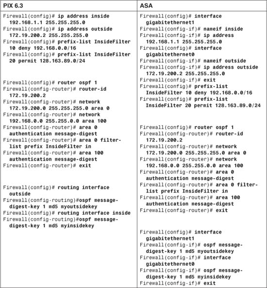
3-3 DHCP Server Functions
A firewall can act as a DHCP server, assigning IP addresses dynamically to requesting clients. A firewall DHCP server returns its own interface address as the client’s default gateway. The interface subnet mask is returned for the client to use as well.
Cisco firewalls support up to 256 active clients at any one time. (The Cisco PIX 501 supports either 32, 128, or 256 clients, depending on the user license.)
No provisions are available for configuring static address assignments. A firewall can manage only dynamic address assignments from a pool of contiguous IP addresses.
Beginning with ASA 7.2(1), a firewall can generate dynamic DNS information based on the DHCP server. This allows DNS records to be updated dynamically, as hosts acquire an IP address. The dynamic DNS feature is covered in detail in the “Updating Dynamic DNS from a DHCP Server” section later in this chapter.
A firewall can also act as a DHCP relay, forwarding DHCP requests received on one interface to DHCP servers found on another interface. DHCP relay is similar to the ip helper-address command on routers and switches running Cisco IOS Software.
The DHCP relay service accepts DHCP request broadcast packets and converts them to DHCP request unicast packets. The unicasts are forwarded to the DHCP servers. After DHCP replies are received, they are relayed back to the requesting client.
Using the Firewall as a DHCP Server
Follow these steps to configure the DHCP server feature:
1. Define an address pool for host assignments:
Firewall(config)# dhcpd address ip1[-ip2] if_name
The pool of available client addresses on the firewall interface named if_name (inside, for example) goes from a lower-limit address ip1 to an upper-limit address ip2. These two addresses must be separated by a hyphen and must belong to the same subnet. In addition, the pool of addresses must reside in the same IP subnet assigned to the firewall interface. In releases before PIX 6.3, only non-outside interfaces were supported. After 6.3, the outside interface can be used, too.
2. Supply clients with domain information.
a. (Optional) Hand out dynamic information obtained by the firewall:
Firewall(config)# dhcpd auto_config [outside]
You can use this command if your firewall is configured to obtain IP address information for its interface from an independent DHCP server. After the DNS and WINS server addresses and the domain name are learned from the DHCP server, the firewall can push those same values out to its own DHCP clients. In this scenario, the firewall usually acts as a DHCP client on its outside interface and as a DHCP server on its inside interface.
or
b. (Optional) Hand out DNS server addresses:
Firewall(config)# dhcpd dns dns1 [dns2]
You can configure up to two DNS server addresses to hand out to DHCP clients. The server IP addresses are given as dns1 and dns2.
c. (Optional) Hand out WINS server addresses:
Firewall(config)# dhcpd wins wins1 [wins2]
WINS servers are used to resolve Microsoft NetBIOS names into IP addresses. You can configure up to two WINS server addresses to hand out to DHCP clients. The WINS IP addresses are given as wins1 and wins2.
d. (Optional) Hand out the domain name:
Firewall(config)# dhcpd domain domain_name
You can configure the domain name that the client will learn and use as domain_name (the fully qualified domain name, such as myexample.com).
3. Define the client lease time:
Firewall(config)# dhcpd lease lease_length
By default, the firewall supplies DHCP replies with lease times of 3600 seconds (1 hour). You can adjust the lease time to be lease_length seconds (300 to 2,147,483,647 seconds).
Tip
If your clients must compete for addresses in a relatively small pool, a shorter lease time is better. After a client is turned off, its lease runs out soon, and another client can be assigned that address.
If most of your clients are stable and stay in use most of the day, you can lengthen the lease time. A longer lease time reserves an address for a client, even if that client turns off and returns later.
Lease times also affect your ability to correlate workstations and their address assignments with Syslog entries from the firewall. Sometimes, you might need to track down which workstation was using a specific address on a certain day and time. The firewall logs only DHCP assignments, so if the lease times are long, the DHCP log entries are sparse and more difficult to find.
4. (Optional) Hand out options for Cisco IP Phones.
Cisco IP Phones must receive additional information about their environment through DHCP. This information is sent as DHCP options.
a. Identify the IP phone TFTP server:
Firewall(config)# dhcpd option 66 {ascii server_name | ip server_ip}
Firewall(config)# dhcpd option 150 ip server_ip1 [server_ip2]
A Cisco IP Phone must find the TFTP server where it can download its configuration. This information is provided as either DHCP option 66 (a single TFTP server) or option 150 (up to two TFTP servers). You can define one or both of these options; the IP phone accepts and tries them both.
If you use option 66, you can use the ascii keyword to define the TFTP server’s host name as server_name (a text string). Otherwise, you can use the ip keyword to define the server’s IP address as server_ip.
If you use option 150, you can define one or two TFTP server addresses.
b. (Optional) Identify the IP phone default routers:
Firewall(config)# dhcpd option 3 ip router_ip1 [router_ip2]
By default, the firewall sends its own interface address as the client’s default gateway. In some cases, there might be two potential gateways or routers for Cisco IP Phones to use. You can define these in DHCP option 3 as router_ip1 and router_ip2.
c. (Optional) Provide a generic DHCP option:
Firewall(config)# dhcpd option code {ascii string | ip ip_address
| hex hex_string}
If you need to provide an arbitrary DHCP option to clients, you can specify the option number as code (0 to 255). The option value can be an ASCII character string, an IP address, or a string of hexadecimal characters (pairs of hex digits with no white space and no leading 0x).
5. (Optional) Adjust the preassignment ping timer:
Firewall(config)# dhcpd ping_timeout timeout
When the firewall receives a DHCP request from a potential client, it looks up the next available IP address in the pool. Before a DHCP reply is returned, the firewall tests to make sure that the IP address is not already in use by some other host. (This could occur if another host had its IP address statically configured without the firewall’s knowledge.)
The firewall sends an ICMP echo (ping) request and waits timeout milliseconds (100 to 10000 ms; the default is 750) for a reply. If no reply occurs in that time frame, it assumes that the IP address is indeed available and assigns it to the client. If an ICMP reply is received from that address, the firewall knows that the address is already taken.
6. Enable the DHCP server:
Firewall(config)# dhcpd enable if_name
The DHCP server starts listening for requests on the firewall interface named if_name (inside, for example). You can define and enable DHCP servers on more than one interface by repeating the sequence of DHCP configuration commands.
Tip
You can display the current DHCP server parameters with the show dhcpd EXEC command. To see the current DHCP client-address bindings, use the show dhcpd bindings EXEC command. To see the number of different DHCP message types received, use the show dhcpd statistics EXEC command.
You can also see information about DHCP activity by using the debug dhcpd event command. This can be useful if you think a client is requesting an address but is never receiving a reply.
DHCP Server Example
A PIX Firewall is configured as a DHCP server for clients on its inside interface. Clients are assigned an address from the pool 192.168.200.10 through 192.168.200.200. They also receive DNS addresses 192.168.100.5 and 192.168.100.6, WINS addresses 192.168.100.15 and 192.168.100.16, and a domain name of mywhatastrangeexample.com.
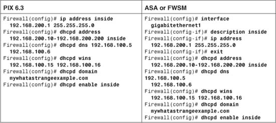
Updating Dynamic DNS from a DHCP Server
Traditionally, hostnames and IP addresses have been associated through the use of DNS, requiring static configurations. While this might be practical for servers, which rarely change their hostnames or addresses, it does not lend itself to timely updates for clients that frequently change IP addresses.
Dynamic DNS (DDNS) solves this problem by keeping the DNS function, but allowing records to be updated dynamically, as they change. DDNS is most useful when it is teamed with a DHCP server; as the DHCP server hands out IP addresses to clients, it can send a DDNS update immediately. This allows mobile or transient clients to keep a stable hostname and to always be found through a DNS lookup.
On the ASA platform, the DDNS database can be updated from the following sources:
• The ASA DHCP server, as it provides IP addresses to PC clients
• The ASA DHCP client, as it requests an address from an ISP
• PC clients, as they send a DHCP request; the ASA can relay the DNS information provided by the clients
On the ASA, DDNS uses the IETF standard method defined in RFC 2136. Through DDNS, the following DNS resource records can be updated for a host:
• A resource record—Contains the hostname-to-address mapping (for example, www.cisco.com resolves to 198.133.219.25)
• PTR resource record—Contains the address-to-hostname mapping (for example, 219.133.198.in-addr.arpa resolves to www.cisco.com)
To use DDNS, you must configure either a DHCP client, a DHCP server, or both on the ASA. The DHCP mechanism is always used to send updates to a DNS server that is DDNS-capable. You can use the following steps to configure DDNS support:
1. Identify DNS servers that support DDNS:
asa(config)# dns server-group DefaultDNS
asa(config-dns-server-group)# dns name-server ip_address
[ip_address2]...[ip_address6]
asa(config-dns-server-group)# exit
You can enter up to six IP addresses of DDNS servers where the ASA can send dynamic updates.
2. Enable DNS use on an interface:
asa(config)# dns domain-lookup if_name
Identify the ASA interface that is closest to the DNS servers. The ASA sends DDNS updates on that interface.
3. Define an update method:
asa(config)# ddns update method method_name
The DDNS update method policy is known by the arbitrary method_name string.
4. Specify the update method:
asa(DDNS-update-method)# ddns [both]
By default, the ASA attempts to update only the A resource record. You can add the both keyword to make it update both the A and PTR resource records.
5. (Optional) Set the maximum update period:
asa(DDNS-update-method)# interval maximum days hours minutes seconds
By default, the ASA sends DDNS updates only as they occur, based on the activity of DHCP clients. You can also set a maximum update interval, so that the ASA does not wait more than a defined time before sending another update. The interval is defined as days (0 to 364), hours (0 to 23), minutes (0 to 59), and seconds (0 to 59) and should be chosen to match the requirements of the DDNS servers.
6. (Optional) Send DDNS updates from the ASA DHCP client:
asa(config)# interface if_name
asa(config-if)# ddns update method_name
asa(config-if)# ddns update hostname hostname
asa(config-if)# ip address dhcp [setroute]
The DDNS method named method_name (configured in Step 3) is used on the specified ASA interface. When the ASA DHCP client sends a DDNS update, it needs to know its own hostname. You can specify the hostname as hostname, as either a fully qualified domain name (FQDN) or as a hostname that is prepended to the ASA’s domain name (configured with the domain-name command).
Finally, the ip address dhcp command starts the DHCP client and requests an IP address for the interface. As soon as an address is obtained, the DHCP client attempts to send its DDNS update to bind the IP address to the hostname.
You can also specify the DDNS policy for the ASA DHCP client with the following interface configuration command:
asa(config-if)# dhcp client update dns [server {both | none}]
By default, the ASA DHCP client does not update its DNS record on its own. Issuing this command enables the client to send DDNS updates through the ASA DHCP server, toward the DNS. The client instructs the server to send only PTR updates, unless the server keyword is added, along with either the both (send both A and PTR updates) or none (send no DDNS updates) keyword.
This command can also be given as a global configuration command, to provide a global policy for all interfaces. You can enter a global and an interface version of the same command; the interface command always overrides the global settings. Be aware that the global version of this command uses a hyphen (dhcp-client), while the interface version does not (dhcp client).
7. (Optional) Send DDNS updates from the ASA DHCP server:
A DHCP server can be configured on an ASA, usually facing the inside or secure side where client PCs are located. The ASA can send DDNS updates based on the requests made from the clients to the DHCP server. You can configure the ASA DHCP server to send DDNS updates with the following global configuration command:
asa(config)# dhcpd update dns [both] [override] [interface if_name]
As soon as this command is given, the ASA DHCP server sends updates for PTR resource records only. You can add the both keyword to send both A and PTR records. If you add the override keyword, the ASA DHCP server overrides the information contained in all DHCP client requests—including the ASA DHCP client configuration. For example, a DHCP client might try to send a PTR record, but the DHCP server can override that by sending both A and PTR records.
If you want to enable DDNS on only a single ASA interface, you can add the interface keyword. Otherwise, the ASA generates DDNS updates on any interface that has a DHCP server configured.
Tip
The ASA DHCP server generates DDNS updates on any interface that has a DHCP server configured. The ASA attempts a reverse DNS lookup on the DHCP client’s IP address, to find the authoritative DNS for the client’s domain. The Start of Authority (SOA) entry is requested for the client’s IP address. If the DNS does not already have the client’s domain configured, along with the SOA information, the ASA cannot register DDNS updates successfully.
In the case of private or RFC 1918 addresses inside the firewall boundary, the DNS does not return a valid SOA for the private subnet unless the DDNS-capable machines in your network are already preconfigured with definitions for your local subnets, along with a correct SOA entry.
Verifying DDNS Operation
Because you can configure both DHCP client and DHCP server on a single ASA, you might become confused about what is actually configured and running on which interfaces. You can use the show dhcpd state command to see where the client and server functions exist, as in the following example.
Firewall# show dhcpd state
Context Configured as DHCP Server
Interface outside, Configured for DHCP CLIENT
Interface inside, Configured for DHCP SERVER
Interface dmz, Not Configured for DHCP
Interface management, Not Configured for DHCP
Firewall#
You can use the show ddns update method to see the configured method and the show ddns update interface command to see the DDNS method that is applied to each ASA interface. Finally, you can view debugging output by entering the debug ddns command.
As an example, suppose an ASA is to be configured to provide DDNS updates to a DNS server. The ASA should have a policy to allow updates to both the A and PTR resource records, using the update method called myddns. On the outside interface, the ASA uses its DHCP client to obtain an address. The DHCP client also is allowed to send DDNS updates with its hostname (asa.mycompany.com) and its newly obtained IP address.
On the inside interface, the ASA should be configured to run a DHCP server for inside clients. As inside clients send DHCP requests, their hostname and assigned IP addresses are sent on as DDNS updates. The following commands could be used to accomplish these example requirements.
Firewall(config)# hostname asa
Firewall(config)# domain-name mycompany.com
Firewall(config)# ddns update method myddns
Firewall(config)# ddns both
!
Firewall(config)# interface Ethernet0/0
Firewall(config-if)# nameif outside
Firewall(config-if)# security-level 0
Firewall(config-if)# ddns update hostname asa.mycompany.com
Firewall(config-if)# ddns update myddns
Firewall(config-if)# ip address dhcp setroute
!
Firewall(config-if)# interface Ethernet0/1
Firewall(config-if)# nameif inside
Firewall(config-if)# security-level 100
Firewall(config-if)# dhcp client update dns
Firewall(config-if)# ip address 192.168.100.1 255.255.255.0
Firewall(config-if)# exit
!
Firewall(config)# dns domain-lookup outside
Firewall(config)# dns server-group DefaultDNS
Firewall(config-dns-server-group)# name-server 128.163.111.7
Firewall(config-dns-server-group)# domain-name mycompany.com
Firewall(config-dns-server-group)# exit
Firewall(config)# dhcp-client update dns
Firewall(config)# dhcpd dns 128.163.97.5 128.163.3.10
Firewall(config)# dhcpd update dns both
!
Firewall(config)# dhcpd address 192.168.100.10-192.168.100.254 inside
Firewall(config)# dhcpd enable inside
Relaying DHCP Requests to a DHCP Server
Follow these steps to configure a firewall to act as a DHCP relay:
1. Define a real DHCP server:
Firewall(config)# dhcprelay server dhcp_server_ip server_ifc
A real DHCP server can be found at IP address dhcp_server_ip on the firewall interface named server_ifc (inside, for example). You can repeat this command to define up to four real DHCP servers.
When DHCP requests (broadcasts) are received on one firewall interface, they are converted to UDP port 67 unicasts destined for the real DHCP servers on another interface. If multiple servers are defined, DHCP requests are relayed to all of them simultaneously.
2. (Optional) Adjust the DHCP reply timeout:
Firewall(config)# dhcprelay timeout seconds
By default, the firewall waits 60 seconds to receive a reply from a real DHCP server. If a reply is returned within that time, it is relayed back toward the client. If a reply is not returned within that time, nothing is relayed back to the client, and any overdue server reply is simply dropped. You can adjust the timeout to seconds (1 to 3600 seconds).
3. (Optional) Inject the firewall interface as the default gateway:
Firewall(config)# dhcprelay setroute client_ifc
When DHCP replies are returned by a real DHCP server, a default gateway could be specified in the reply packet. By default, this information is passed on through the firewall so that the client receives it.
You can configure the firewall to replace any default gateway information with its own interface address. This causes the DHCP reply packet to list the firewall interface closest to the client, the interface named client_ifc, as the default gateway.
4. Enable the DHCP relay service:
Firewall(config)# dhcprelay enable client_ifc
The DHCP relay service is started only on the firewall interface named client_ifc (inside, for example). This is the interface where DHCP clients are located.
DHCP Relay Example
A DHCP relay is configured to accept DHCP requests from clients on the inside interface and relay them to the DHCP server at 192.168.1.1 on the DMZ interface. The firewall waits 120 seconds for a reply from the DHCP server. The firewall’s inside interface address is given to the clients as a default gateway. You can use the following commands to accomplish this:
Firewall(config)# dhcprelay server 192.168.1.1 dmz
Firewall(config)# dhcprelay timeout 120
Firewall(config)# dhcprelay setroute inside
Firewall(config)# dhcprelay enable inside
Tip
You can monitor DHCP relay activity by looking at the output from the show dhcprelay statistics EXEC command. The output shows the counters of the various DHCP operations relayed to and from the real DHCP server, as in the following example:
Firewall# show dhcprelay statistics
Packets Relayed
BOOTREQUEST 0
DHCPDISCOVER 7
DHCPREQUEST 3
DHCPDECLINE 0
DHCPRELEASE 0
DHCPINFORM 0
BOOTREPLY 0
DHCPOFFER 7
DHCPACK 3
DHCPNAK 0
3-4 Multicast Support
To participate in forwarding and inspecting IP multicast traffic, a firewall can coexist with multicast routers running Protocol-Independent Multicast (PIM) sparse mode.
A firewall can operate as an IGMP proxy agent, also called a stub router. For all multicast-related operations, the firewall acts on behalf of the recipients. IGMP requests from recipient hosts on one firewall interface are intercepted, inspected, and relayed to multicast routers on another firewall interface.
Beginning with ASA 7.0 and FWSM 3.1(1), a firewall can also be configured to act as a PIM router so that it communicates with other PIM routers to build a complete multicast distribution tree.
After recipients join multicast groups, the firewall can intercept, inspect, and relay multicast traffic from the source on one interface to the recipients on another interface.
Multicast Overview
A network uses three basic types of IP traffic:
• Unicast—Packets that are sent from one source host address to a single destination host address. Unicast packets are forwarded by finding the destination IP address in routing tables.
• Broadcast—Packets that are sent from one source host address to a broadcast destination address. The destination can be all hosts (255.255.255.255), a directed broadcast to a subnet (that is, 192.168.10.255), or some portion of a subnet. A router or Layer 3 device does not forward these by default unless some method of relaying has been configured.
• Multicast—Packets that are sent from one source host address to a special group-based destination address. The destination represents only the hosts that are interested in receiving the packets, and no others. A router or Layer 3 device does not forward these packets by default unless some form of multicast routing is enabled.
Two extremes are covered here—a unicast, which travels from host to host, and a broadcast, which travels from one host to everyone on a segment. Multicast falls somewhere in the middle, where the intention is to send packets from one host to only the users who want to receive them—namely, those in the designated multicast group. Ideally, the recipients of multicast packets could be located anywhere, not just on the local segment.
Multicast traffic is generally unidirectional. Because many hosts receive the same data, it makes little sense to allow one of the hosts to send packets back toward the source over the multicast mechanism. Instead, a receiving host can send return traffic to the source as a unicast. Multicast traffic is also sent in a best-effort connectionless format. UDP (connectionless) is the commonly used format, whereas TCP (connection-oriented) is not.
Hosts that want to receive data from a multicast source can join or leave a multicast group dynamically. In addition, a host can decide to become a member of more than one multicast group at any time. The principal network task is then to figure out how to deliver multicast traffic to the group members without disturbing other uninterested hosts.
Multicast Addressing
Routers and switches must have a way to distinguish multicast traffic from unicasts or broadcasts. This is done through IP addressing by reserving the Class D IP address range, 224.0.0.0 through 239.255.255.255, for multicasting. Network devices can quickly pick out multicast IP addresses by looking at the four most-significant bits, which are always 1110.
How does a router or switch relate a multicast IP address to a MAC address? There is no ARP equivalent for multicast address mapping. Instead, a reserved Organizationally Unique Identifier (OUI) value is set aside so that multicast MAC addresses always begin with 0100.5e (plus the next-lower bit, which is 0). The lower 28 bits of the multicast IP address must also be mapped into the lower 23 bits of the MAC address by a simple algorithm.
Some of the IP multicast address space has been reserved for a particular use:
• Complete multicast space (224.0.0.0 through 239.255.255.255)—The entire range of IP addresses that can be used for multicast purposes.
• Link-local addresses (224.0.0.0 through 224.0.0.255)—Used by network protocols only on the local network segment. Routers do not forward these packets.
This space includes the all-hosts address 224.0.0.1, all-routers 224.0.0.2, OSPF-routers 224.0.0.5, and so on. These are also known as fixed-group addresses because they are well-known and predefined.
• Administratively scoped addresses (239.0.0.0 through 239.255.255.255)—Used in private multicast domains, much like the private IP address ranges from RFC 1918. These addresses are not routed between domains, so they can be reused.
• Globally scoped addresses (224.0.1.0 through 238.255.255.255)—Used by any entity. These addresses can be routed across an organization or the Internet, so they must be unique and globally significant. (Think of this range as neither local nor private; it is the rest of the multicast range.)
Forwarding Multicast Traffic
IP multicast traffic must be forwarded from one network interface to another, just like any other Layer 3 packets are handled. The difference is in knowing where to forward the packets. For example, unicast IP packets have only one destination interface on a router or firewall (even if multiple paths exist). Multicast IP packets, however, can have many destination interfaces, depending on where the recipients are located.
Cisco firewalls running PIX 6.2 or 6.3 have a limited multicast capability. They can act only as a multicast forwarding proxy, also known as a stub multicast router (SMR), depending on other routers in the network to actually route the multicast packets. The firewalls can determine where the multicast recipients are located on their own interfaces. They must be statically configured to forward the multicast traffic between a source and the recipients.
Beginning with ASA 7.0 and FWSM 3.1(1), Cisco firewalls can participate in multicast routing by using the PIM routing protocol. This lets a firewall communicate with other PIM routers to distribute multicast traffic dynamically and along the best paths.
Multicast Trees
The routers in a network must determine a forwarding path to get multicast packets from the source (sender) to each of the recipients, regardless of where they are located. Think of the network as a tree structure. At the root of the tree is the source, blindly sending IP packets to a specific multicast address. Each router along the way sits at a branch or fork in the tree. If a router knows where all the multicast group recipients are located, it also knows which branches of the tree to replicate the multicast packets onto. Some routers have no downstream recipients, so they do not need to forward the multicast traffic. Other routers might have many downstream recipients.
This tree structure is somewhat similar to a spanning-tree topology because it has a root at one end and leaf nodes (the recipients) at the other end. The tree is also loop-free so that none of the multicast traffic gets fed back into the tree.
Tip
In multicast routing, the router nearest the multicast source is called the first-hop router. It is the first hop that multicast packets reach when they leave the source. Routers at the tree’s leaf nodes, nearest the multicast receivers, are called last-hop routers. They are the last hop that multicast packets reach at the end of their journey.
Reverse Path Forwarding
Multicast routers usually have one test to perform on every multicast packet they receive. Reverse Path Forwarding (RPF) is a means to make sure packets are not being injected back into the tree at an unexpected location.
As a packet is received on a router interface, the source IP address is inspected. The idea is to verify that the packet arrived on the same interface where the source can be found. If this is true, the packet is actually proceeding out the tree’s branches, away from the source. If this is not true, someone else has injected the packet on an unexpected interface, headed back down the tree’s branches toward the source.
To perform the RPF test, a PIM router looks up the source address in its unicast routing table. If the next-hop interface used to reach the source address also matches the interface where the packet was received, the packet can be forwarded or replicated toward the multicast recipients. If not, the packet is quietly discarded.
IGMP: Finding Multicast Group Recipients
How does a router know of the recipients in a multicast group, much less their locations? To receive multicast traffic from a source, both the source and every recipient must first join a common multicast group, known by its multicast IP address.
A host can join a multicast group by sending a request to its local router. This is done through Internet Group Management Protocol (IGMP). IGMPv1 is defined in RFC 1112, and its successor, IGMPv2, is defined in RFC 2236. Think of IGMP as a means of maintaining group membership only on the local router.
When several hosts join a group by contacting their local routers, it is the multicast routing protocol (such as PIM) that “connects the dots” and forms the multicast tree between routers.
Note
Keep in mind that IGMP is always used on multicast routers and Cisco firewalls to interact with multicast hosts. In PIX 6.3 and earlier, Stub Multicast Routing offers IGMP for local group membership and IGMP forwarding so that multicast routers can use the IGMP information on a broader scale.
PIM is available only beginning with ASA 7.0 and FWSM 3.1(1). The firewall then becomes a true multicast router, running both PIM and IGMP.
IGMPv1
To join a multicast group, a host can dynamically send a Membership Report IGMP message to its local router (or firewall). This message tells the router what multicast address (group) the host is joining. The multicast address is used as the IGMP packet’s destination IP address, as well as the group address requested in the message.
Every 60 seconds, one router on each network segment queries all the directly connected hosts to see if they are interested in receiving multicast traffic. This router is known as the IGMPv1 Querier. It functions simply to invite hosts to join a group.
Queries are sent to the 224.0.0.1 all-hosts multicast address for quick distribution. (By definition, every host must listen to the all-hosts address; no group membership is required.) If a host is interested in joining a group, or if it wants to continue receiving a group that it has already joined, it must respond to the router with a membership report.
Hosts can join multicast groups at any time. However, IGMPv1 does not have a mechanism to allow a host to leave a group if it is no longer interested in the group’s content. Instead, routers age a multicast group out of an interface (network segment) if no membership reports are received for three consecutive query intervals. This means that, by default, multicast traffic is still sent onto a segment for up to 3 minutes after all the group members have stopped listening.
Notice that a router does not need to keep a complete host membership list for each multicast group that is active. Rather, it needs to record only which multicast groups are active on which interfaces.
IGMPv2
IGMP version 2 introduced several differences from the first version. Queries can be sent as General Queries to the all-hosts address (as in IGMPv1). They also can be sent as Group-Specific Queries, sent only to members of a specific group.
In addition, hosts are allowed to leave a group dynamically. When a host decides to leave a group it has joined, it sends a Leave Group message to the all-routers address (224.0.0.2). All routers on the local segment take note, and the Querier router decides to investigate further. It responds with a Group-Specific Query message, asking if anyone is still interested in receiving traffic for that group. Any other hosts must reply with a Membership Report. Otherwise, the Querier router safely assumes that there is no need to continue forwarding the group traffic on that segment.
Note
If any IGMPv1 routers are on a segment, all multicast routers on the segment must run IGMPv1. Otherwise, the IGMPv1 routers cannot understand the IGMPv2 messages.
IGMPv2 is enabled by default on Cisco router and firewall interfaces.
PIM: Building a Multicast Distribution Tree
PIM is a routing protocol that can be used to forward multicast traffic. PIM operates independently of any particular IP routing protocol. Therefore, PIM uses the IP unicast routing table and does not keep a separate multicast routing table. (The unicast routing table is itself routing protocol-independent because one or more routing protocols can be used to populate a single table.)
PIM can operate in two modes, depending on the density of the recipients in a multicast group. Cisco has developed a third hybrid mode as well. The PIM modes are as follows:
• PIM dense mode (PIM-DM)—Multicast routers assume that multicast recipients are located everywhere, on every router and every router interface. After a tree is built, its branches are pruned if a multicast group has no active recipients.
• PIM sparse mode (PIM-SM)—Multicast routers construct a distribution tree by adding branches only as recipients join a multicast group.
• PIM sparse-dense mode—Multicast routers operate in dense or sparse mode, depending on how the multicast group is configured.
In addition, two versions of the PIM protocol can be used in a network: PIM version 1 and PIM version 2.
Cisco firewalls running ASA 7.0 or later, as well as FWSM 3.1(1) or later, can operate only in PIM sparse mode, although they can coexist with other routers running PIM-SM or PIM sparse-dense mode.
PIM Sparse Mode
PIM sparse mode takes a “bottom-up” approach to constructing a multicast distribution tree. The tree is built by beginning with the recipients or group members at the end leaf nodes and extending back toward a central root point.
Sparse mode also works on the idea of a shared tree structure, where the root is not necessarily the multicast source. Instead, the root is a PIM-SM router that is centrally located in the network. This root router is called the rendezvous point (RP).
The tree from the RP to the group members is actually a subset of the tree that could be drawn from the source to the group members. If a multicast source anywhere in the network can register for group membership with the RP, the tree can be completed end-to-end. Because of this, the sparse mode tree is called a shared tree.
Note
Sparse mode multicast flows are designated by a (source,destination) pair. The letters S and G represent a specific source and group, respectively. An asterisk (*) can also be used to represent any source or destination. For example, multicast flows over the shared tree are described as (*,G) because the shared tree allows any source to send to a group G.
In PIM-SM, the shared tree is built using the following basic sequence of steps:
1. A recipient host joins a multicast group by sending an IGMP Membership Report to the local router.
2. The router adds an (*,G) entry in its own multicast routing table, where G represents the group IP address. The router also maintains a list of outbound interfaces where group recipients are located.
3. The router sends a PIM Join request for (*,G) toward the RP at the tree’s root.
4. The neighboring PIM router receives the Join request, adds a (*,G) entry in its own table, and adds the arriving interface to its list of outbound interfaces for the group. The neighboring PIM router then relays the Join request toward the RP.
5. When the RP finally receives the PIM Join request, it too adds a (*,G) entry and the arriving interface to its own table. The shared tree has now been built from a recipient host to the RP.
For example, consider the network shown in Figure 3-16. A firewall separates a public and private network and also acts as the RP for PIM multicast routing. Three receivers (end-user hosts) in the network join a single multicast group in preparation to receive traffic from a multicast source.
Figure 3-16 A Sample Network with PIM Multicast Routers
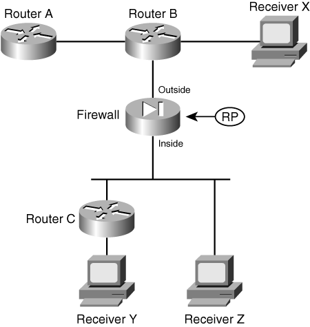
Figure 3-17 illustrates the group membership process. On the left side of the figure, the multicast receivers X, Y, and Z each send an IGMP membership request to join group address 239.0.0.1. Router B receives the request from Receiver X and also creates a multicast route entry (*,239.0.0.1) that points back toward the receiver. Router B also sends a PIM Join message for (*,239.0.0.1) toward the RP, which adds the link between it and the firewall to the multicast tree.
Figure 3-17 Building a Shared Multicast Tree with PIM
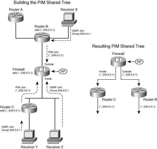
Router C takes similar steps for the IGMP request it receives from Receiver Y. Receiver Z is a slightly different case; the firewall receives its IGMP request directly because it is directly connected. The firewall adds a (*,239.0.0.1) multicast route entry to its table, pointing back toward the receiver on the inside interface.
Notice how all the IGMP membership reports terminate at the closest router (or firewall) while PIM Join messages travel from router to router. After the RP receives all the Join messages, the multicast tree is complete, as shown in the right portion of Figure 3-17. The network topology has been redrawn slightly to show how the RP (firewall) is at the root of the tree. This is called a PIM shared tree because it is used by all the devices participating in the multicast group. Routers that have no active multicast group receivers (Router A, for example) do not send a PIM Join message, so they do not become part of the tree.
A shared tree always begins with the RP at the root and progresses downward toward the leaf nodes, where the receivers are located. Only the PIM routers are shown, because they actually build and use the tree. PIM shared trees are always unidirectional. Multicast packets can only start at the RP and be sent toward the receivers.
Finally, a multicast source must also join the group so that traffic can flow toward the receivers. The left portion of Figure 3-18 illustrates this process, where the source is connected to Router C.
Figure 3-18 Adding a Multicast Source to PIM Trees
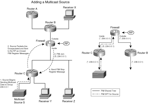
When a source joins a multicast group, the following steps take place:
1. A source S begins sending traffic to the multicast group address (239.0.0.1 in the example). Up to this point, the multicast tree has not been extended to the source. In fact, notice that the source is sending traffic upstream toward the RP! In the unidirectional shared tree, this is not allowed. This point is dealt with in the next few steps.
2. The nearest PIM router receives the traffic destined for the multicast group and realizes that it is coming from a source. The router must register the source with the RP so that it can become a part of the tree. The multicast packets are encapsulated in PIM Register messages that are sent to the RP as unicasts.
3. The RP unencapsulates the Register messages and sends the original multicast packets down the tree toward the receivers.
The RP also sends an (S,G) PIM Join message downstream toward the source address so that a tree can be built from the source to the RP. In the example, this is a (S,239.0.0.1) multicast flow. The idea is to construct a path to carry multicast data from the source to the tree’s root (the RP) so that it can flow downward toward the receivers.
Note
The tree built from the source to the RP is not a part of the PIM shared tree. Instead, it is called a shortest path tree (SPT) because it follows a path from a router (the RP in this case) directly to the source. Because the SPT is separate from the shared tree, multicast packets can travel upward toward the RP without interfering with packets traveling downward from the RP toward the receivers.
In effect, these are two unidirectional trees with the RP always serving as the root.
4. After the SPT has been built from the source to the RP, there is no need to keep encapsulating the source data as Register messages. The RP sends a PIM Register Stop message toward the source. When the leaf node router at the source receives this, it stops sending the Register messages and begins using the new SPT path.
The right portion of Figure 3-18 illustrates the resulting tree structures. The solid arrows show the PIM shared tree, from the RP down to the routers where receivers are located. The broken-line arrows represent the SPT that is built from the source up to the RP.
Although it is not shown in this example, last-hop PIM routers are allowed to perform an SPT switchover to attempt to build a more direct path to the multicast source. This process is very similar to the steps described previously, where specific (S,G) flows are added to the PIM routers along the path. After an SPT switchover occurs, the RP is no longer required to be at the root of the tree if a better path can be found.
To simplify the tree structure and improve efficiency, PIM can also support a bidirectional mode. If every PIM router supporting a multicast group is configured for bidirectional mode, a single multicast tree is formed to connect the multicast source to all its receivers.
Multicast packets can flow up or down the tree as necessary to disperse in the network. The PIM routers take on designated forwarder (DF) roles, deciding whether to forward multicast packets onto a network segment in the appropriate direction. Because a single bidirectional tree is used, the multicast source can join the group without the PIM source registration process.
PIM RP Designation
In PIM sparse mode, every PIM router must know the RP’s identity (IP address). After all, each router has to send PIM Join/Prune messages toward the RP by using its unicast routing table to find the correct interface.
The simplest method of identifying the RP is to manually configure its address in each PIM router. If there are not many PIM routers to configure, this method is very straightforward. However, if there are many PIM routers or if the RP address is likely to change in the future, manual configuration can be cumbersome.
Note
Beginning with ASA 7.0 and FWSM 3.1(1), static RP configuration is the only option available. Other more dynamic RP discovery methods are described in this section because they might be used on PIM routers in your network.
Cisco also provides a proprietary means to automatically inform PIM-SM routers of the appropriate RP for a group. This is known as Auto-RP. Routers that can potentially become an RP are configured as candidate RPs. These routers advertise their capability over the Cisco-RP-Announce multicast address 224.0.1.39.
These announcements are picked up by one or more centrally located and well-connected routers that have been configured to function as mapping agents. A mapping agent collects and sends RP-to-group mapping information to all PIM routers over the Cisco-RP-Discovery multicast address 224.0.1.40.
A mapping agent can limit the scope of its RP discovery information by setting the time-to-live (TTL) value in its messages. This limits how many router hops away the information will still be valid. Any PIM router within this space dynamically learns of the candidate RPs that are available to use.
The second version of PIM also includes a dynamic RP-to-group mapping advertisement mechanism. This is known as the bootstrap router method and is standards-based.
PIMv2 is similar to the Cisco Auto-RP method. First, a bootstrap router (BSR) is identified; this router learns about RP candidates for a group and advertises them to PIM routers. Only the BSR and candidate RPs have to be configured; all other PIM routers learn of the appropriate RP dynamically from the BSR.
These bootstrap messages permeate the entire PIM domain. The scope of the advertisements can be limited by defining PIMv2 border routers, which do not forward the bootstrap messages further.
Note
If Auto-RP is being used in your network, be aware that an ASA or FWSM firewall cannot participate in the Auto-RP process. The firewall must have the PIM RP address statically configured.
However, the candidate RP announcements over 224.0.1.39 and the Router Discovery messages over 224.0.1.40 can pass through the firewall to reach PIM routers on the other side. Therefore, the Auto-RP mechanism can still work across the firewall, but the firewall cannot directly benefit from the dynamic RP discovery itself.
Configuring PIM
Use the following steps to configure PIM multicast routing on a firewall running ASA 7.0 or later, or a FWSM running 3.1(1) or later. Keep in mind that you have to configure explicit access list rules to permit multicast host access through a firewall.
All multicast traffic is subject to normal firewall inspection, with the exception of IGMP, PIM, OSPF, and RIPv2. You do not have to configure address translation for the multicast group addresses, however. The firewall automatically creates an internal identity NAT for addresses such as 239.0.0.1, 239.255.148.199, and so on.
1. Enable multicast routing:
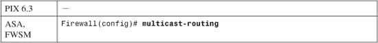
Enabling multicast routing brings up PIM and IGMP on every firewall interface.
Tip
You can verify the current PIM status on each interface by using the following command:
Firewall# show pim interface {state-on | state-off}
For example, a firewall with PIM enabled on its inside and outside interfaces produces the following output:
Firewall# show pim interface state-onAddress Interface PIM Nbr Hello DR DR Count Intvl Prior192.168.198.1 inside on 1 30 1 192.168.198.4192.168.93.135 outside on 1 30 1 this systemFirewall# show pim interface state-offAddress Interface PIM Nbr Hello DR DR Count Intvl Prior192.168.77.1 dmz off 0 30 1 not electedFirewall#
![]()
The RP is located at ip_address. By default, it is used for all 224.0.0.0/4 multicast group addresses. You can use the RP for specific multicast addresses by configuring a standard access list named acl_name and applying it in this command.
For example, the following commands can be used to define an RP for group addresses 239.0.0.0 through 239.0.0.15:
Firewall(config)# access-list MyGroups standard permit 239.0.0.0 255.255.255.240
Firewall(config)# pim rp-address 192.168.100.1 MyGroups
Tip
Because the firewall cannot participate in any dynamic RP discovery methods (Auto-RP or BSR), the RP address must be statically configured. If the firewall will act as the RP itself, use one of the firewall’s own interface addresses as the RP address in this command. Then, for other routers, configure a static RP address using the address of the nearest firewall interface. Even though the firewall is configured with only one of its own interfaces as the RP address, it automatically supports the RP function for neighboring PIM routers on all other interfaces.
Tip
By default, the firewall operates in normal PIM sparse mode for the multicast groups and RP. You can add the bidir keyword if the RP and its associated PIM routers are operating in bidirectional mode. This allows multicast traffic to move toward and away from the RP in the sparse mode tree.
Note
If you configure bidirectional mode on one PIM router (or firewall) in your network, you must configure it on all of them. Otherwise, the bidirectional PIM routers introduce traffic.
3. (Optional) Adjust PIM parameters on a firewall interface.
a. Specify an interface:

The interface named if_name is selected.
b. (Optional) Disable multicast support on an interface:

If PIM is disabled on an interface and you need to reenable it, you can use the pim interface configuration command.
c. (Optional) Set the PIM hello period:

A firewall periodically sends PIM hello messages on each interface where PIM is enabled. By default, hellos are sent every 30 seconds. You can set the interval to seconds (1 to 3600).
Note
The PIM hello interval does not have to be configured identically on neighboring routers. This is because each router advertises its own holdtime, or the amount of time a neighbor should wait to receive a hello message before expiring the neighbor relationship. This is usually set to 3 times the hello interval, or a default value of 90 seconds.
The hello interval affects how quickly a PIM neighbor can be discovered and how quickly it is declared unreachable if it becomes unresponsive.
d. (Optional) Set the designated router (DR) priority:

PIM advertises an interface priority so that connected PIM routers can elect a designated router. By default, a DR priority of 1 is used. You can set this to priority (0 to 4294967295). A higher priority is more likely to win the election; in the case of a tie, the router interface with the highest IP address wins.
e. (Optional) Adjust the Join/Prune message interval:

Multicast routers must send periodic PIM Join/Prune messages to their upstream neighbors to maintain their position in the multicast tree. The idea is to maintain the forwarding state to a multicast router (or firewall) only if it still has active participants connected; otherwise, the state might be stale and should be flushed.
By default, Join/Prune messages are sent every 60 seconds. You can set this interval to seconds (10 to 600) if needed.
Tip
If you decide to change the time interval, be aware that it should be configured identically on all multicast routers participating in PIM. If three Join/Prune messages are missed (180 seconds with the default 60-second interval), the forwarding state is removed. Therefore, all routers should agree on the basic Join/Prune time interval.
4. (Optional) Filter PIM Register messages:
PIM Register messages are sent by first-hop DRs to the RP to inform it that a multicast source exists. The original multicast packets sent by the source are encapsulated and sent as unicast Register messages.
You can filter the PIM Register messages so that you have better control over where legitimate multicast sources or servers can be located and permitted to operate.
a. Define a filter:
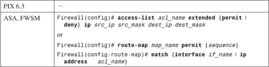
You can filter Register messages based on any combination of the source address (first-hop DR address) and destination address (RP). Keep in mind that PIM Register messages are unicast to the RP and are not sent to the multicast group address.
You can define the filter using an extended access list or route map. Only Register messages that are permitted by the ACL or route map are allowed to reach their destination at the RP.
b. Apply the filter to PIM:
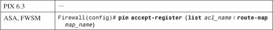
For example, you could use the following commands to allow the first-hop router 192.168.10.10 to register a directly connected multicast source with the RP located at 192.168.1.10:
Firewall(config)# access-list RegFilter extended permit ip host 192.168.10.10
host 192.168.1.10
Firewall(config)# pim accept-register list RegFilter
5. (Optional) Prevent SPT switchover:
![]()
Multicast routers normally form a shared tree structure with the RP as the root. Multicast traffic must travel from the source through the RP and then on to the receivers.
By default, last-hop or leaf node routers with directly connected multicast receivers can (and do) join an SPT by sending a Join message directly to the multicast source. In effect, the resulting SPT has the fewest router hops from source to receiver and might not include the RP.
This can be useful if the RP is not located strategically or if the RP introduces latency with the multicast traffic passing through it. However, you might not want the tree structure to be altered for one or more multicast groups in your network. When the firewall is acting as a last-hop PIM router, you can prevent it from switching over to an SPT by using this command.
If you use the infinity keyword with no other arguments, the firewall must stay with the shared tree for all its groups. Otherwise, you can configure a standard access list that permits the specific multicast group addresses that should be kept on the shared tree. Apply the access list with the group-list acl_name keywords. The firewall is allowed to switch over to an SPT for all other groups.
6. (Optional) Define a static multicast route to a source:
In normal operation, a firewall running PIM dynamically builds a table of multicast “routes” based on the PIM and IGMP membership requests it receives. Multicast routes (mroutes) represent how multicast traffic is forwarded to group addresses—from a source address to a destination interface.
You can define static mroute entries to override or supplement the dynamic entries with the following command:
![]()
A static multicast route correlates a multicast source address with its Class D multicast group address. The firewall can then inspect and forward traffic from the source on one interface to recipients (and multicast routers) on another interface.
The multicast source is identified by its IP address src, subnet mask smask (usually 255.255.255.255), and the firewall interface named in_if_name where it connects. The multicast destination is the actual Class D group IP address dst, subnet mask dmask, and the firewall interface named out_if_name where recipients are located.
Beginning with ASA 7.0 and FWSM 3.1(1), only the out_if_name is given. Notice that this form of the command resembles a reverse path rather than a traditional unicast static route. In other words, the mroute is defined by its source and not by a destination. Its only function is to define how a multicast source can be reached, independent of the normal unicast routing information.
On an ASA or FWSM, you can also specify an administrative distance (0 to 255; the default is 0) to influence how the firewall performs its RPF check. Normally, RPF involves checking the unicast routing table on the firewall, but a static mroute configuration overrides that. You can prefer other sources of routing information by adjusting the mroute distance, where a lower distance is more trusted or preferable.
Table 3-4 lists the default administrative distance assigned to routes on a firewall.
Table 3-4 Default Administrative Distances by Route Type
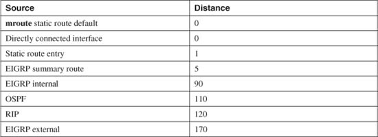
For example, if the unicast routes learned through static route commands or directly connected interface addresses should be trusted more than the mroute entry for RPF, you could use the following command:
Firewall(config)# mroute 10.1.1.10 255.255.255.255 inside 10
Here, the multicast source is located on the inside interface at 10.1.1.10, and all multicast receivers are located on the outside interface. The administrative distance of 10 still makes this entry more preferable for RPF than unicast routes learned through RIP or OSPF.
Using a Multicast Boundary to Segregate Domains
IP Multicast address space is broken down into several ranges, each reserved for a different function. Some ranges, such as link-local addresses and administratively scoped addresses, are not meant to be routed across Layer 3 boundaries. Others, such as globally scoped addresses, are free to be routed anywhere—across organizational boundaries and across the Internet.
Administratively scoped addresses (239.0.0.0 through 239.255.255.255) are analogous to the private address ranges defined in RFC 1918. These addresses are locally significant, so it is not unusual to find the same addresses appearing in many different locations or organizations. What happens when RP routers, each supporting its own administratively scope address range, become neighbors so that they begin sharing a multicast routing domain? Now multiple instances of the 239.0.0.0/8 multicast range exist, and the routing to that range becomes ambiguous.
If an ASA running 7.2(1) or later is located between multicast domains, you can configure it to act as a multicast boundary. In this role, the ASA matches multicast group addresses against an access list and blocks all multicast traffic in any direction except the addresses permitted by the access list. You can use the following steps to configure a multicast boundary.
1. Block multicast traffic in a standard access list:
asa(config)# access-list acl_name deny mcast_addr mask
The range of multicast group addresses to be stopped at the boundary is defined by mcast_addr and mask. The subnet mask should be given in the usual subnet mask format—not as an inverse mask used in Cisco IOS platforms. For example, you can identify the entire administratively scoped range by the following command:
asa(config)# access-list mcast_boundary deny 239.0.0.0 255.0.0.0
2. Permit other multicast traffic in the standard access list:
asa(config)# access-list acl_name permit mcast_addr mask
As soon as the administratively scoped range has been identified and denied in step 1, you can identify any or all other multicast addresses to be permitted. For example, you can permit the full range of multicast address space (224.0.0.0 through 239.255.255.255) with the following command:
asa(config)# access-list mcast_boundary permit 224.0.0.0 240.0.0.0
3. Apply the standard access list to the boundary interface:
asa(config)# interface if_name
asa(config-if)# multicast boundary acl_name [filter-autorp]
You can add the filter-autorp keyword to have the ASA filter any Auto-RP discovery and announcement messages that attempt to cross the multicast boundary, too. This prevents a PIM router on one side of the boundary from becoming an RP on the other side for the denied multicast address range.
As an example, an ASA’s outside interface on ethernet0/0 could be made into a multicast boundary with the following command:
asa(config)# interface ethernet0/0
asa(config-if)# multicast boundary mcast_boundary filter-autorp
Filtering PIM Neighbors
An ASA can also be configured to prevent multicast routers on one interface from establishing a PIM neighbor relationship with multicast routers on other interfaces. In this role, the ASA filters PIM messages coming from source addresses identified by an access list. You might want to use this feature to prevent rogue or unauthorized routers from becoming PIM neighbors with your protected multicast routers.
You can use the following steps to configure PIM neighbor filtering:
1. Define an access list to filter PIM router source addresses:
asa(config)# access-list acl_name {permit | deny} ip_addr mask
Use the permit keyword to allow PIM messages to or from the IP addresses defined by ip_addr mask. The deny keyword can be used to filter or block PIM messages to or from specific addresses. For example, the following commands permit only outside multicast routers 10.10.1.10 and 10.10.1.20 to become PIM neighbors with inside routers. All other router addresses are filtered automatically because of the implicit deny at the end of the access list.
asa(config)# access-list pimneighbors permit 10.10.1.10 255.255.255.255
asa(config)# access-list pimneighbors permit 10.10.1.20 255.255.255.255
2. Apply the access list to a PIM neighbor filter on an ASA interface:
asa(config)# interface if_name
asa(config-if)# pim neighbor-filter acl_name
As an example, the access list from Step 1 could be applied to the outside interface (ethernet0/0) with the following commands:
asa(config)# interface ethernet0/0
asa(config-if)# pim neighbor-filter pimneighbors
Filtering Bidirectional PIM Neighbors
ASA 7.0 introduced the ability to enable PIM sparse mode neighbor relationships to form through an ASA. Beginning with ASA 7.2(1), bidirectional PIM relationships can also form through an ASA. In addition, you can configure an ASA to filter bidirectional neighbors so that you can control which multicast routers can participate in a bidirectional tree and a DF election.
You can use the following steps to configure a bidirectional PIM neighbor filter:
1. Define an access list to filter bidirectional PIM router source addresses:
asa(config)# access-list acl_name {permit | deny} ip_addr mask
Use the permit keyword to allow PIM messages to or from the IP addresses defined by ip_addr mask. The deny keyword can be used to filter or block PIM messages to or from specific addresses.
2. Apply the access list to a PIM bidirectional neighbor filter on an interface:
asa(config)# interface if_name
asa(config-if)# pim bidir-neighbor-filter acl_name
Configuring Stub Multicast Routing (SMR)
A firewall can be configured to participate as a stub multicast router. In this case, it acts as a proxy between fully functional PIM routers and multicast participants. Only IGMP messages are relayed between firewall interfaces; PIM routing is not used. In fact, as soon as SMR is configured, any existing pim rp-address commands for multicast routing are automatically removed from the configuration.
This is the only multicast function available in PIX release 6.3. It is optional in ASA releases if PIM is undesirable. The steps for configuring SMR are as follows:
1. Define the proxy agent (stub router).
a. Enable multicast support toward multicast routers:

The IGMP proxy agent becomes active on the firewall interface named if_name, where the multicast routers can be found. If a multicast source is on the outside, the outside interface should be used here. (This command is not necessary for IGMP proxy on an ASA platform.)
b. (Optional) Add static multicast routes if the multicast source is on the inside:
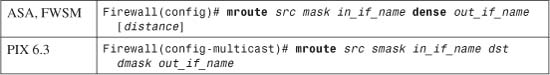
Use this command when a multicast source is on an internal firewall interface sending traffic to recipients on the outside. Because the firewall isolates any multicast routing between the recipients and the internal source, static routes must be configured.
A static multicast route correlates a multicast source with its Class D multicast group address. The firewall can then inspect and forward traffic from the source on one interface to recipients (and multicast routers) on another interface.
The multicast source is identified by its IP address src, subnet mask smask (usually 255.255.255.255), and the firewall interface named in_if_name where it connects. The multicast destination is the actual Class D group IP address dst, subnet mask dmask, and the firewall interface named out_if_name where recipients are located.
Beginning with ASA 7.0(1), you must provide the out_if_name along with the dense keyword. Notice that this form of the command resembles a reverse path rather than a traditional unicast static route. In other words, the mroute is defined by its source and not by a destination. In fact, the multicast destination address is not specified.
With ASA releases, you can also specify an administrative distance (0 to 255; the default is 0) to influence how the firewall performs its RPF check. Normally, RPF involves checking the unicast routing table on the firewall, but a static mroute configuration overrides that. You can prefer other sources of routing information by adjusting the mroute distance, where a lower distance is more trusted or preferable.
Table 3-5 lists the default administrative distance assigned to routes on a firewall.
Table 3-5 Administrative Distance by Route Type
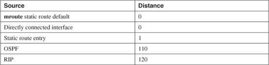
For example, if the unicast routes learned through static route commands or directly connected interface addresses should be trusted more than the mroute entry for RPF, the following command could be used:
Firewall(config)# mroute 10.1.1.10 255.255.255.255 inside dense outside 10
Here, the multicast source is located on the inside interface at 10.1.1.10, and all multicast receivers are located on the outside interface. The administrative distance of 10 still makes this entry more preferable for RPF than unicast routes learned through RIP or OSPF.
2. (Optional) Configure multicast support for the recipients.
a. Enable multicast support on an interface where recipients are located:

The IGMP proxy agent becomes active on the firewall interface named interface_name. This is usually the “inside” interface, closest to the multicast recipients. You can also use this command to configure multicast support on other firewall interfaces. (This command is not necessary for IGMP proxy on an ASA or FWSM platform.)
b. Enable the IGMP forwarding proxy:
The proxy agent listens for IGMP join and leave requests on the multicast interface and relays them to multicast routers on the interface named if_name. This is usually the outside interface, although you can repeat the command if recipients are located on other interfaces, too.
In ASA and FWSM releases, this command is used in interface configuration mode on the interface (in_if_name, such as GigabitEthernet1) that will forward IGMP traffic to recipients on interface if_name (inside, for example). For example, to forward IGMP from the inside interface (GigabitEthernet1) to recipients located on the outside interface (GigabitEthernet0), you would use the following commands:
Firewall(config)# interface GigabitEthernet1
Firewall(config-if)# description Inside
Firewall(config-if)# igmp forward interface outside
Configuring IGMP Operation
IGMP is used on firewall interfaces to handle multicast group membership for directly connected hosts. You can use the following configuration steps to tune or change the IGMP operation:
1. Select an interface to tune:
![]()
All subsequent IGMP configuration commands are applied to the interface you specify.
2. (Optional) Disable IGMP on the interface:
![]()
On ASA and FWSM platforms, IGMP is enabled on all firewall interfaces as soon as the multicast-routing command is used. You can use the no igmp command if you need to disable IGMP on the interface because no multicast hosts are present or allowed.
3. (Optional) Set the IGMP version:
![]()
By default, a firewall communicates with hosts using IGMP version 2. You can change this to version 1 if needed. The IGMP version should match the capabilities of the recipient hosts.
4. (Optional) Tune IGMP query operation.
a. (Optional) Set the IGMP query interval:

This specifies how often, in seconds, the firewall sends IGMP query messages to the hosts to determine group memberships. The seconds value can be 1 to 3600; the PIX 6.3 default is 60 seconds, and the ASA and FWSM defaults are 125 seconds.
b. (Optional) Set the maximum query response time:
This command is used to determine how long the router waits for a response from a host about group membership. The default is 10 seconds. If a host does not respond quickly enough, you can lengthen this time value to seconds (1 to 25).
c. (Optional) Set the querier response timer:

By default, the firewall waits 255 seconds to hear from the current IGMP querier before it takes over that role. You can adjust the query timeout to seconds (60 to 300).
5. (Optional) Set limits on multicast group membership.
a. (Optional) Limit the number of hosts per multicast group:

By default, a firewall maintains the forwarding state of up to 500 multicast recipients per interface. You can limit this further to number (1 to 500) hosts.
b. (Optional) Limit the number of multicast groups supported:

By default, up to 500 multicast groups can be supported on a firewall interface. You can change this limit to number (0 to 2000) groups if needed.
c. (Optional) Control the groups that hosts can join:

When client hosts or multicast recipients attempt to join a multicast group, the firewall can filter the requests. If you place restrictions on groups, recipients can join only the group addresses that are permitted by the access list named acl_name.
Tip
You need to configure an access list before using this command. The access list should be of the following form:
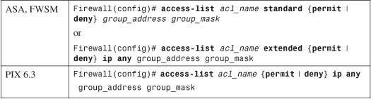
Tip
Multicast groups are identified by their Class D multicast addresses, which can be given as a network address and subnet mask. With ASA or FWSM, you can use either a standard or extended access list. In either case, the group_address and group_mask represent the multicast group.
For example, suppose multicast users on the inside interface should be allowed to join only group addresses 239.0.0.0 through 239.0.0.255. You would use the following commands:
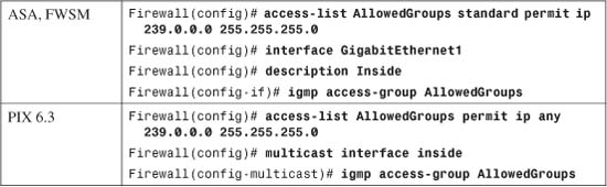
6. (Optional) Configure the firewall to become a member of a multicast group:
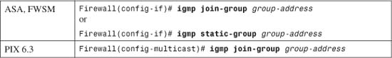
The igmp join-group command allows you to specify a multicast group-address (a Class D multicast address) for the firewall interface to join. By joining a group, the firewall interface begins to accept packets sent to the multicast address. Therefore, it becomes a pingable member of the multicast group—something that can be a valuable testing tool.
As soon as the interface joins the group, the firewall also becomes a surrogate client so that multicast traffic can be forwarded to recipients that do not support IGMP. The interface group membership keeps the multicast path alive so that those hosts can continue to receive the traffic from the multicast source.
With ASA or FWSM, you can use the igmp static-group command to cause the firewall interface to join a group without actually accepting the multicast traffic itself. Instead, packets sent to the multicast group-address are forwarded to any recipients on the interface.
Stub Multicast Routing Example
A firewall separates a multicast source from its recipients. The source is located on the outside interface, and the recipients are on internal networks found on the inside interface. Recipients can join multicast groups only in the 224.3.1.0/24 and 225.1.1.0/24 ranges. The PIX 6.3 configuration commands needed are as follows:
Firewall(config)# access-list mcastallowed permit ip any 224.3.1.0 255.255.255.0
Firewall(config)# access-list mcastallowed permit ip any 225.1.1.0 255.255.255.0
Firewall(config)# multicast interface outside
Firewall(config-multicast)# exit
Firewall(config)# multicast interface inside
Firewall(config-multicast)# igmp forward interface outside
Firewall(config-multicast)# igmp access-group mcastallowed
Now, consider the same example, where the source and recipients trade places. If the multicast source (192.168.10.1) is located on the inside of the firewall, with recipients on the outside, the configuration could look like the following:
Firewall(config)# access-list mcastallowed permit ip any 224.3.1.0 255.255.255.0
Firewall(config)# access-list mcastallowed permit ip any 225.1.1.0 255.255.255.0
Firewall(config)# multicast interface inside
Firewall(config-multicast)# igmp forward interface outside
Firewall(config-multicast)# mroute 192.168.10.1 255.255.255.255 inside 224.3.1.0
255.255.255.0 outside
Firewall(config-multicast)# mroute 192.168.10.1 255.255.255.255 inside 225.1.1.0
255.255.255.0 outside
Firewall(config)# multicast interface outside
Firewall(config-multicast)# igmp access-group mcastallowed
PIM Multicast Routing Example
An ASA or FWSM is to be configured for PIM multicast routing between its inside and outside interfaces. The firewall acts as the RP for any multicast group address beginning with 239.
You could use the following configuration commands:
Firewall(config)# multicast-routing
Firewall(config)# interface GigabitEthernet1
Firewall(config-if)# nameif inside
Firewall(config-if)# security-level 100
Firewall(config-if)# ip address 192.168.198.1 255.255.255.0
Firewall(config-if)# exit
Firewall(config)# access-list PIMgroups standard permit 239.0.0.0 255.0.0.0
Firewall(config)# pim rp-address 192.168.198.1 PIMgroups
Verifying IGMP Multicast Operation
You can display the current multicast configuration on a firewall running PIX 6.3 with the show multicast command, as shown in the following example:
Firewall# show multicast
multicast interface outside
igmp access-group mcastallowed
multicast interface inside
igmp forward interface outside
igmp access-group mcastallowed
Firewall#
As soon as multicast is configured and IGMP becomes active on some firewall interfaces, you can display IGMP activity with this EXEC command:
![]()
If you do not use any arguments, the output displays all firewall interfaces configured for multicast. Otherwise, you can specify a multicast group or an interface.
In addition, the output displays any currently active multicast groups. For example, the following multicast group addresses are shown to be active with receivers on the inside and outside interfaces of an ASA or FWSM:
Firewall# show igmp groups
IGMP Connected Group Membership
Group Address Interface Uptime Expires Last Reporter
239.0.0.1 inside 1d01h 00:04:16 192.168.198.4
239.255.148.199 inside 1d01h 00:04:14 192.168.198.198
239.255.199.197 inside 1d01h 00:04:15 192.168.198.198
239.255.255.250 inside 1d01h 00:04:16 192.168.198.198
224.0.1.40 outside 1d01h 00:04:01 128.163.93.129
239.0.0.1 outside 1d01h 00:04:00 128.163.93.129
Firewall#
You can display the current IGMP settings on a specific firewall interface with this command:
![]()
The following example provides some sample output from this command:
Firewall# show igmp interface inside
inside is up, line protocol is up
Internet address is 192.168.198.1/24
IGMP is enabled on interface
Current IGMP version is 2
IGMP query interval is 125 seconds
IGMP querier timeout is 255 seconds
IGMP max query response time is 10 seconds
Last member query response interval is 1 seconds
Inbound IGMP access group is:
IGMP limit is 500, currently active joins: 4
Cumulative IGMP activity: 4 joins, 0 leaves
IGMP querying router is 192.168.198.1 (this system)
Firewall#
Verifying PIM Multicast Routing Operation
After you enable multicast routing on an ASA or FWSM, you should verify that it is seeing hello messages from its PIM router neighbors. You can do this with the following command:

For example, the following output shows that a firewall is communicating with two PIM neighbors located on two different interfaces:
Firewall# show pim neighbor
Neighbor Address Interface Uptime Expires DR pri Bidir
192.168.198.4 inside 1d02h 00:01:19 1 (DR)
10.1.93.1 outside 01:54:40 00:01:19 N/A
Firewall#
The Uptime column shows how long the firewall has been successfully receiving PIM hello messages from the peer router. The firewall must receive the next hello before the time shown in the Expires column reaches 0.
Tip
You can also verify that the firewall is sending its own PIM hellos by checking its neighbor status from a directly connected PIM router. For example, the router located on the firewall’s outside interface shows the following information about the firewall as a PIM router:
Router# show ip pim neighbor
PIM Neighbor Table
Neighbor Address Interface Uptime Expires Ver Mode
10.1.93.2 Vlan4 01:59:15 00:01:34 v2 (DR)
Router#
You can display the current multicast routing table with the following command:
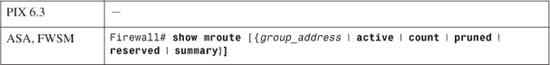
Finally, a firewall maintains information about the PIM routing topology. This includes entries for each multicast flow that the firewall has received a PIM Join/Prune message about, as well as the flow uptime, RP for the group, firewall interfaces actively forwarding traffic for the flow, and various flags about the flow state.
As a quick summary of multicast flows in the topology table, you can use the following command:
Firewall# show pim topology route-count
PIM Topology Table Summary
No. of group ranges = 6
No. of (*,G) routes = 6
No. of (S,G) routes = 2
No. of (S,G)RPT routes = 2
Firewall#
The actual PIM topology information is displayed with the show pim topology command, as shown in the following example. Here, the firewall is the RP (192.168.198.1) for several of the multicast groups. A Cisco IP/TV multicast source is located at 192.168.198.198, using multicast group 239.255.199.197 for streaming video and 239.255.148.199 for streaming audio.
Firewall# show pim topology
IP PIM Multicast Topology Table
Entry state: (*/S,G)[RPT/SPT] Protocol Uptime Info
Entry flags: KAT - Keep Alive Timer, AA - Assume Alive, PA - Probe Alive,
RA - Really Alive, LH - Last Hop, DSS - Don't Signal Sources,
RR - Register Received, SR
(*,224.0.1.40) DM Up: 1d13h RP: 0.0.0.0
JP: Null(never) RPF: ,0.0.0.0 Flags: LH DSS
outside 1d13h off LI LH
(*,239.0.0.1) SM Up: 1d13h RP: 192.168.198.1*
JP: Join(never) RPF: Tunnel1,192.168.198.1* Flags: LH
inside 1d13h fwd Join(00:02:45) LI
outside 1d13h fwd LI LH
(*,239.255.148.199) SM Up: 1d13h RP: 192.168.198.1*
JP: Join(never) RPF: Tunnel1,192.168.198.1* Flags: LH
outside 00:00:33 fwd LI LH
inside 1d13h fwd Join(00:03:14) LI
(192.168.198.198,239.255.148.199)RPT SM Up: 1d13h RP: 192.168.198.1*
JP: Prune(never) RPF: Tunnel1,192.168.198.1* Flags: KAT(00:02:59) RA RR
inside 1d13h off Prune(00:03:14)
(192.168.198.198,239.255.148.199)SPT SM Up: 00:04:00
JP: Join(never) RPF: inside,192.168.198.198* Flags: KAT(00:02:59) RA RR
No interfaces in immediate olist
(*,239.255.199.197) SM Up: 1d13h RP: 192.168.198.1*
JP: Join(never) RPF: Tunnel1,192.168.198.1* Flags: LH
outside 00:00:33 fwd LI LH
inside 1d13h fwd Join(00:03:20) LI
(192.168.198.198,239.255.199.197)RPT SM Up: 1d13h RP: 192.168.198.1*
JP: Prune(never) RPF: Tunnel1,192.168.198.1* Flags: KAT(00:02:56) RA RR
inside 1d13h off Prune(00:03:20)
(192.168.198.198,239.255.199.197)SPT SM Up: 00:04:08
JP: Join(never) RPF: inside,192.168.198.198* Flags: KAT(00:02:56) RA RR
No interfaces in immediate olist
(*,239.255.255.250) SM Up: 1d13h RP: 192.168.198.1*
JP: Join(never) RPF: Tunnel1,192.168.198.1* Flags: LH
outside 00:01:23 fwd LI LH
inside 1d13h fwd Join(00:02:59) LI
Firewall#
Each multicast flow is listed as (*,G), (S,G), or (S,G)RPT, where * means any source, S is a specific source address, and G is the multicast group address. In addition, the following values are shown:
• Multicast protocol—SM (sparse mode, used for most flows) or DM (dense mode).
• Flow uptime—The time elapsed since the flow was first created.
• RP—The address of the RP for the flow or group.
• JP—Join or Prune activity.
• RPF—Reverse path forwarding entry, or the interface where multicast data is expected to arrive.
In the example, the RPF is often shown as Tunnel1,192.168.198.1. In this case, the firewall acts as the RP, and bidirectional mode is not used. Therefore, the multicast data must pass from the source to the RP over an SPT to the RP before being forwarded down the shared PIM tree. The “tunnel” is a logical interface within the firewall that points back to the source.
• Flags—Various flags representing the flow’s state.
• Interface information—A list of interfaces involved in the flow, their current forwarding state (fwd or off), and the most recent Join or Prune event with the elapsed time.
Note
The firewall automatically creates a multicast flow for (*,224.0.1.40), which is used for Cisco Auto-RP Discovery messages. The flow is listed as DM because it is a hop-by-hop announcement that does not depend on a sparse mode RP. To dynamically discover an RP, the discovery protocol cannot rely on an RP.
In the example, two multicast flows of interest are shaded. The first, (*,239.255.199.197), represents the multicast flow from any source to group 239.255.199.197. This is the video stream of data being pushed down the shared multicast tree toward the receivers that have joined the group.
Note that the RPF or the source of the data is listed as Tunnel1,192.168.198.1, which is the firewall’s inside interface. The firewall is acting as the RP, so it is receiving multicast data from the source over a special internal “tunnel” interface.
The second flow, (192.168.198.198,239.255.199.197)SPT, represents the multicast flow from the source (192.168.198.198) to the multicast group. This data is actually being fed to the RP over an SPT built for this purpose—hence the SPT designation in the flow descriptor. The RPF points to the inside interface, where the source is located.