
Chapter 4. Firewall Management
Refer to the following sections for information about these topics:
• 4-1: Using Security Contexts to Make Virtual Firewalls—Presents the configuration steps needed to make one physical firewall platform emulate multiple virtual firewalls.
• 4-2: Managing the Flash File System—Explains the types of images that are stored in nonvolatile firewall memory and how to work with them.
• 4-3: Managing Configuration Files—Presents the methods you can use to configure firewalls and manage their configuration files.
• 4-4: Automatic Updates with an Auto Update Server—Discusses a way to leverage a central server to update image and configuration files on multiple firewalls automatically.
• 4-5: Managing Administrative Sessions—Presents the configuration steps necessary to permit administrative users to access a firewall for configuration, monitoring, or troubleshooting.
• 4-6: Firewall Reloads and Crashes—Discusses how to perform a controlled firewall reload or reboot. After an unexpected firewall crash, you can also examine “post mortem” information about the cause of the crash.
• 4-7: Monitoring a Firewall with SNMP—Explains Simple Network Management Protocol (SNMP) and how it can be used to obtain system information from a firewall.
Any firewall that is deployed in a network must also be managed. Firewall administrators need to be able to make configuration changes, define virtual firewall contexts for other entities, maintain the firewall operating system and configuration files, and monitor firewall operation.
This chapter presents the configuration steps and background information you need to perform these management functions.
4-1 Using Security Contexts to Make Virtual Firewalls
On Adaptive Security Applianace (ASA) and Firewall Services Module (FWSM) platforms, you can configure one physical firewall chassis to act as multiple virtual firewalls. Each virtual firewall is called a context because it is one partition or instance of a fully functional firewall.
Even though all the configured contexts are emulated by a single firewall CPU, the traffic inspection and security policies of each are kept separate, as if they were being handled by a dedicated physical firewall. Therefore, each context can be configured and managed by different administrators, or they can all be managed by one administrator who has access to them.
Traditionally, one physical firewall would be added to a network every time a new firewall function was needed. The cost of adding firewalls in this way is incremental. The ability to run multiple security contexts on a single firewall provides a way to limit the cost of firewall hardware. Firewall contexts can be added according to license limits. This capability does come with a trade-off, however, because all contexts must share the resources available on the hardware platform.
Security contexts can be useful in both service provider and enterprise environments. A service provider can partition one physical firewall into multiple security contexts that can be assigned to customers for a recurring cost. Each customer can configure and manage his or her respective context.
In an enterprise setting, multiple contexts could be assigned to individual departments or organizations where there is no overlap in security policies. Each department would operate its own firewall context independently of others. On the “public” side of each firewall, each context could connect to a shared or common Internet feed.
Security Context Organization
A Cisco firewall that can support security contexts can operate in only one of the following modes:
• Single-context security mode—One context is configured on one physical firewall platform. This is the traditional or default mode of operation.
• Multiple-context security mode—Two or more contexts can be configured on one physical firewall.
In multiple-context security mode, a firewall is organized into the following functions, each having its own user interface:
• System execution space—A special area where individual contexts are defined and physical firewall resources are mapped to them. Because the system execution space does not use security policies and cannot provide network connectivity, it cannot really function as a true firewall context.
• Administrative context—A fully functional virtual firewall that is used mainly to manage the physical firewall. You can configure security policies, network addressing and routing, and any other firewall function needed for administrative use. This context operates independently of any other context.
• User contexts—Fully functional virtual firewalls that can be configured and handed over to a third party if needed. Each user context can have its own security policies, network addressing, access control, and so on. Almost anything that can be configured on a single-firewall platform can be configured on a user context.
Figure 4-1 shows how a single physical firewall can be organized to provide multiple security contexts. Each context has its own set of virtual firewall interfaces that are mapped from the physical or VLAN firewall interfaces.
Figure 4-1 Single- and Multiple-Context Security Modes
In practice, the physical firewall platform might not have enough interfaces to be able to map them one-to-one with context interfaces. In Figure 4-1, the firewall would need two unique physical interfaces for each context! Even if there were enough interfaces to go around, you might not want to use all of them in the first place when only a few could provide the necessary connectivity.
Sharing Context Interfaces
Multiple-context mode allows some flexibility in mapping interfaces. You can map one physical interface to one context interface when isolation from other firewalls is required.
You can also map one physical interface to several context interfaces so that the contexts share a single connection. This might be practical in an enterprise setting, where each context is designated for a different department. Most likely, an enterprise would have a single path toward the public Internet. Every department would share that path, provided by one physical firewall interface. As that interface is mapped to each context, the resulting logical or mapped interface would become the context’s outside interface. Figure 4-2 illustrates this concept.
Figure 4-2 Mapping Common Interfaces to Contexts
Physical interfaces can be shared in any configuration. For example, if two firewall contexts need to provide access to some authentication servers that they share, one physical interface could be mapped to those two contexts and no others.
Finally, consider that all contexts are really emulated by one firewall platform. As packets enter a physical firewall interface, the firewall CPU must determine which context is the true destination.
If one physical interface is mapped to one context interface, the firewall CPU simply takes packets arriving on that interface and puts them in the queue for that context interface. The mapped context must be the virtual firewall that will inspect and handle the inbound traffic.
Suppose one physical interface is mapped to interfaces in several contexts. Now when packets arrive on that interface, the firewall CPU must decide which of the mapped contexts is the correct destination firewall.
A firewall running in multiple-context mode uses a classifier function to sort out which context should actually process each inbound packet. In effect, a classifier is positioned at each firewall interface to decide which context should receive packets as they arrive. Figure 4-3 illustrates this concept.
Figure 4-3 Using a Packet Classifier to Match Inbound Traffic to a Security Context
The classifier is simple; if it can find a unique source interface or destination address, it has enough information to hand off a packet to a context. The classifiers shown at the bottom of Figure 4-3 have an easy job because their source interfaces are mapped to a single unique context. Packets arriving on the inside interfaces are passed directly to the respective context inside interfaces to begin the normal firewall stateful inspection process.
However, if firewall interfaces are shared between contexts, as in the topmost interface shown in Figure 4-3, the problem becomes a bit more difficult. The classifier at the top of the figure is faced with the task of finding a unique destination context for each inbound packet.
A classifier does this by attempting to find the packet destination address defined in one of the connected contexts. The destination address must be uniquely identified in one of the following ways:
• A global address defined in a static NAT entry
• A global address used in an xlate entry
• A firewall interface address (used when packets are destined for the firewall itself)
A classifier also works in only one direction. Each packet that arrives on a shared interface is examined so that it can be sent to a specific context. Because of this, you should work through scenarios with a connection originating on each side of the firewall to make sure that the classifier process will work properly. The classifier must find the destination address as a global address entry in one (and only one) of the security contexts.
For example, Figure 4-4 shows a simple arrangement in which two security contexts are configured to share their outside interfaces toward the public network. The left side of the figure shows what happens when a connection is initiated from inside host 192.168.1.100 to outside host 198.133.219.25. Because the inside context interfaces are not shared, the classifier nearest to the inside host can simply send the packets to Context A, where the host is connected. At Context A, the inside address is translated to global address 207.246.96.47, because of a static NAT configuration.
Figure 4-4 Example of Sharing Outside Context Interfaces
For the return traffic from the outside host, the classifier examines arriving packets on the shared outside interfaces. The destination address is 207.246.96.47, which is found as a global address in the xlate table on Context A. Therefore, traffic originating on the inside network can make the round trip successfully.
On the right side of Figure 4-4, a connection originates from the outside host, located on the shared interfaces. Here, the destination address 207.246.96.47 is again found as a global address in a static NAT xlate entry on Context A. This traffic too can make the round trip.
What if a dynamic NAT or PAT were used instead of a static NAT? In that case, the dynamic NAT would be configured to use one or more global addresses during translation. In Figure 4-4, the global address is 207.246.96.46, which could be found in xlate entries for connections passing through Context A. The classifiers on either side of the firewall would have no problem finding the global address on Context A.
Issues with Sharing Context Interfaces
If you decide to share the inside context interfaces, you should be aware of a classifier limitation. Consider the arrangement shown in Figure 4-5, where Contexts A and B share their inside interfaces.
Figure 4-5 Example of Sharing Inside Context Interfaces

The classifier must examine packets entering from the inside networks to decide which context should receive them. A search is made to find the packet destination addresses in the context xlate tables. In particular, the classifier can find only global addresses in the tables. This means that there must already be a static NAT entry in place for the outside address to appear as a global address.
In practice, this is seldom successful. The outside context interface usually points toward a public network such as the Internet, where most or all of the addresses exist but are not configured into the context. Usually, a default route points the way toward the public network where a context can find every other host that is not explicitly configured. However, the classifier must use actual global addresses, not routes, so it cannot determine which context to use to reach outside hosts.
To remedy this situation, you would have to configure static NAT entries for each of the outside host addresses that might be involved in connections from the inside hosts! That might result in two extremes:
• The list of outside hosts would be too small to be practical for the inside users.
• The number of outside hosts would be much too great to try to configure.
In most cases, the inside context interfaces are not shared because inside networks tend to be isolated and protected from every other network. However, another scenario deserves consideration. With multiple security contexts at your disposal, you might consider nesting or cascading contexts to provide layers or shells of security in an enterprise network.
Consider Figure 4-6, in which the left portion represents such a hierarchy of security contexts. The topmost context might be used at the boundary with the Internet to provide common security policies for the entire enterprise. Then other contexts might be nested below that to serve individual departments or buildings within the enterprise.
Figure 4-6 Example of Nesting Security Contexts
To test this scenario, the structure has been reduced on the right portion of the figure to show a cascade of just two security contexts. This turns out to be very similar to the previous example, in which the inside context interfaces were shared. However, it might not be obvious that the middle classifier is positioned where two context interfaces are shared. The Context A inside interface is shared with the Context B outside interface to build the cascading structure.
Again, when packets originating from the inside hosts reach this classifier, chances are that no static NAT or global address will be configured or found for outside Internet hosts. Therefore, that classifier cannot decide whether to send the packets to Context A or back to Context B.
As a result, you should plan on nesting or cascading security contexts only if you can provide static NAT entries for each outside host that inside hosts will be allowed to contact. Otherwise, you can build a nested arrangement from separate physical security appliance platforms, where classifiers are not needed between firewalls or contexts.
Solving Shared Context Interface Issues with Unique MAC Addresses
By default, every physical ASA interface uses its burned-in address (BIA) as its Media Access Control (MAC) address. Also, every subinterface of a physical interface uses the physical interface’s MAC address. After the ASA is configured for multiple context mode, system context interfaces (both physical and subinterfaces) are allocated to other contexts. This means that the MAC address of a system context interface is reused on each of its associated context interfaces.
For example, consider an ASA that has the following system context configuration. Physical interface Ethernet0 is shared across all contexts as the single link to the outside world. Each context has a unique subinterface of Ethernet1 to use as its inside interface, as shown in the following system context configuration:
admin-context admin
context admin
allocate-interface Ethernet0
allocate-interface Ethernet1
config-url flash:/admin.cfg
!
context ContextA
allocate-interface Ethernet0
allocate-interface Ethernet1.1
config-url flash:/ContextA.cfg
!
context ContextB
allocate-interface Ethernet0
allocate-interface Ethernet1.2
config-url flash:/ContextB.cfg
Next, it is useful to see how the ASA allocates its MAC addresses. In the following example, the system context interface MAC addresses are displayed with the show interface command. Notice that each physical interface (Ethernet0, Ethernet1, and so on) has a unique address. The MAC addresses for subinterfaces (Ethernet1.1 and Ethernet1.2) are not shown; they simply inherit the address of their parent physical interfaces.
asa-a# changeto system
asa-a# show interface | include (Interface | MAC)
Interface Ethernet0 "", is up, line protocol is up
MAC address 000e.d7e6.af77, MTU not set
Interface Ethernet1 "", is up, line protocol is up
MAC address 000e.d7e6.af78, MTU not set
Interface Ethernet1.1 "", is up, line protocol is up
Interface Ethernet1.2 "", is up, line protocol is up
Interface Ethernet2 "Failover", is up, line protocol is up
MAC address 0005.5d19.019c, MTU 1500
Interface Ethernet3 "", is administratively down, line protocol is down
MAC address 0005.5d19.019d, MTU not set
Interface Ethernet4 "", is administratively down, line protocol is down
MAC address 0005.5d19.019e, MTU not set
Interface Ethernet5 "", is administratively down, line protocol is down
MAC address 0005.5d19.019f, MTU not set
asa-a#
Finally, each context is visited to display the MAC addresses of its own interfaces. Because system context interface Ethernet0 is allocated to each of the other contexts as a shared outside interface (also called Ethernet0), notice that the highlighted MAC addresses are identical:
asa-a# changeto context admin
asa-a/admin# show interface | include (Interface | MAC)
Interface Ethernet0 "outside", is up, line protocol is up
MAC address 000e.d7e6.af77, MTU 1500
Interface Ethernet1 "inside", is up, line protocol is up
MAC address 000e.d7e6.af78, MTU 1500
asa-a/admin#
asa-a/admin# changeto context ContextA
asa-a/ContextA# show interface | include (Interface | MAC)
Interface Ethernet0 "outside", is up, line protocol is up
MAC address 000e.d7e6.af77, MTU 1500
Interface Ethernet1.1 "inside", is up, line protocol is up
MAC address 000e.d7e6.af78, MTU 1500
asa-a/ContextA#
asa-a/ContextA# changeto context ContextB
asa-a/ContextB# sh interface | include (Interface | MAC)
Interface Ethernet0 "outside", is up, line protocol is up
MAC address 000e.d7e6.af77, MTU 1500
Interface Ethernet1.2 "inside", is up, line protocol is up
MAC address 000e.d7e6.af78, MTU 1500
asa-a/ContextB#
Reusing the MAC addresses does not usually pose a problem because neighboring devices can still see a correspondence between a context interface’s IP address and its MAC address. But what about the example case where the same physical or subinterface is allocated to several different firewall contexts? Each of the allocated context interfaces would have a unique IP address from the same shared subnet, but would reuse the same MAC address.
Neighboring devices might not be able to distinguish one context from another because of the shared MAC address. However, the ASA can usually accept traffic destined to the shared MAC address and figure out which context interface is the real recipient. The ASA uses a classifier function to examine incoming packets and pass them along to the correct context. The classifier works through the following sequence of conditions to map a packet’s destination address to a context:
1. A unique interface—When one interface is allocated to only one context, the destination context is obvious.
2. A unique MAC address—The destination MAC address is found on only one context interface.
3. A unique NAT entry—A unique destination Internet Protocol (IP) address is needed, either through a global address configured in a static NAT entry or found in the xlate table.
Beginning with ASA 7.2(1), you can configure the ASA to use unique MAC addresses on every subinterface and context interface. Physical (system context) interfaces continue to use their burned-in addresses, whereas context interfaces receive MAC addresses that are automatically generated. You can use the following global configuration command to assign unique MAC addresses:
asa(config)# mac-address auto
This command can be used only in the system execution space because that is the source of all interface allocation. As soon as you enter the command, the interface MAC addresses is changed. You can revert back to the original interface MAC addresses by using the no mac-address auto command.
The MAC addresses are automatically generated according to the format spelled out in Table 4-1.
Table 4-1 ASA-Generated MAC Address Format
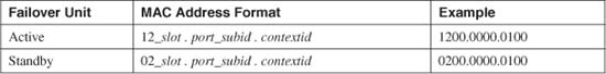
The slot is the interface slot number, or 0 for platforms without slots. The port is the interface port number, and subid is the ASA’s internal subinterface number. The contextid field is the context index, a number the ASA uses internally. You should not worry about what the internal numbering schemes mean—just know that you can easily distinguish the active and standby addresses by the leading 1 or 0 and that each context has a unique identifier.
Continuing the previous example, the mac-address auto command has been entered. The MAC addresses for each of the ASA’s contexts are shown in the following output.
asa-a# changeto system
asa-a# show interface | include (Interface | MAC)
Interface Ethernet0 "", is up, line protocol is up
MAC address 000e.d7e6.af77, MTU not set
Interface Ethernet1 "", is up, line protocol is up
MAC address 000e.d7e6.af78, MTU not set
asa-a# changeto context admin
asa-a/admin# show interface | include (Interface | MAC)
Interface Ethernet0 "outside", is up, line protocol is up
MAC address 1200.0000.0100, MTU 1500
Interface Ethernet1 "inside", is up, line protocol is up
MAC address 1201.0000.0100, MTU 1500
asa-a/admin#
asa-a/admin# changeto context ContextA
asa-a/ContextA# show interface | include (Interface | MAC)
Interface Ethernet0 "outside", is up, line protocol is up
MAC address 1200.0000.0200, MTU 1500
Interface Ethernet1.1 "inside", is up, line protocol is up
MAC address 1201.0001.0200, MTU 1500
asa-a/ContextA#
asa-a/ContextA# changeto context ContextB
asa-a/ContextB# show interface | include (Interface 165168| MAC)
Interface Ethernet0 "outside", is up, line protocol is up
MAC address 1200.0000.0300, MTU 1500
Interface Ethernet1.2 "inside", is up, line protocol is up
MAC address 1201.0002.0300, MTU 1500
asa-a/ContextB#
The ASA automatically generates its MAC addresses using carefully selected parameters. The first six hex digits of the MAC address are referred to as the Organizational Unique Identifier (OUI) or the vendor code. Cisco uses 02xxxx and 12xxxx, neither of which is registered to another vendor. This should produce MAC addresses that are unique within your network, without duplicating the addresses used by other devices.
Tip
If you are running ASA 7.2(1) or later in multiple context mode, you should always enable unique interface MAC addresses with the mac-address auto command. You have no downside to using this command; after it has been configured, your firewall is always ready for any type of context arrangement, including shared interfaces and stacked or nested contexts.
In some rare cases, you could find that an automatically derived MAC address is conflicting with that of another device. How would you know if that happens? You might find that an ASA context is behaving erratically or you might see the following Syslog message in the ASA logs:
%ASA-4-405001: Received ARP request collision from 192.168.1.177/0201.0001.0200 on
interface inside
To remedy this situation, you can use the following interface configuration command to manually configure the ASA context interface MAC address to a different, unique value:
asa(config)# interface if_name
asa(config-if)# mac-address mac_address [standby mac_address]
The MAC address is entered in dotted triplet format (H.H.H), such as 0015.c557.f9bd. If your ASA is configured as part of a failover pair, remember to configure both the active and standby unit interface MAC addresses.
Configuration Files and Security Contexts
The firewall’s flash memory file system is accessible only from the system execution space. This is because Flash is considered a controlled resource, available only to the physical firewall’s administrators. If an individual user context is given over to be managed by a third party, it would not make sense to allow that third party to make changes to or allocate all of the firewall flash for his or her own use.
Where, then, are the firewall image and configuration files stored for a user context? None of the contexts runs its own firewall operating system image. Only one image is run in multiple-context mode, and that image is managed only by the system execution space. All other contexts appear to run the same image, as shown by the output generated by the show version command.
Configuration files, however, are used and maintained by each context. They have the following characteristics:
• The system execution space has both startup and running configuration files that are stored in the flash memory. The startup configuration file can be read, written, and copied, but it is kept in a hidden flash file system.
• Admin and user contexts have both startup and running configuration files. The startup configuration files can be stored in the flash file system or on an external TFTP, FTP, or HTTP server. When an external server is used, the user context administrators can have complete autonomy over the configuration and use of their firewall context.
• The system execution space configuration defines where each context’s startup configuration file will be located.
Guidelines for Multiple-Context Configuration
You can configure and use several different types of contexts on a physical firewall or security appliance:
• The system execution space—Although this is not a true context itself, it is the foundation for all other contexts.
• The admin context—A fully functional virtual firewall that can be used to administer the physical firewall platform.
• One or more arbitrarily named user contexts—Each context operates as an independent virtual firewall.
Each has a specific role within the firewall platform, making configuration somewhat confusing.
The system execution space handles context definition, overall firewall modes of operation, and the physical firewall resources. Therefore, it should be configured before resources and features become available to other contexts.
You can configure the following types of features in the system execution space:
• Physical firewall interfaces (speed, duplex, negotiation, descriptions, VLAN associations, and operational status)
• System images (firewall operating system and PIX Device Manager/Adaptive Security Device Manager [PDM/ASDM] management application)
• Firewall startup configuration file
• Context mode (single or multiple)
• Firewall mode (routing or transparent)
• Context definitions (configuration files, interface allocation, or mapping)
• Firewall failover
• Saving crash information
• Firewall system clock
You must enter firewall license activation keys from the system execution space. In addition, the system execution space provides all access to the firewall’s flash file system.
However, the system execution space has no networking capability of its own. To access external network resources, such as a TFTP server containing the firewall image, the system execution space must work in conjunction with the admin context, where normal IP addressing and address translation are configured.
You should consider each nonsystem context to be a fully functional standalone firewall. Therefore, you can configure the admin and user contexts with all the firewall features presented in this book.
Initiating Multiple-Context Mode
Follow these steps to prepare a firewall for multiple-security context support:
1. Verify multiple-context licensing:
Firewall# show activation-key
A firewall can run in multiple-context mode only if it has been licensed to do so. As well, the maximum number of security contexts is set by the license. You can display the number of contexts supported by the current license, as shown in the following output:
Firewall# show activation-key
Serial Number: 401262144
Running Activation Key: 0xcc05f166 0xd4c17b68 0x98501048 0x818cf190
0x4133d195
License Features for this Platform:
Maximum Physical Interfaces : 10
Maximum VLANs : 100
Inside Hosts : Unlimited
Failover : Active/Active
VPN-DES : Enabled
VPN-3DES-AES : Enabled
Cut-through Proxy : Enabled
Guards : Enabled
URL-filtering : Enabled
Security Contexts : 5
GTP/GPRS : Enabled
VPN Peers : Unlimited
This machine has an Unrestricted (UR) license.
The flash activation key is the SAME as the running key.
2. (Optional) Install a new license activation key:
Firewall# activation-key key
You might need to install a new activation key if multiple-context mode is disabled or if you need to increase the number of supported contexts.
The key given here is a string of five groups of characters, each consisting of four pairs of hexadecimal digits. You can add a 0x prefix to each group of hex digits to denote the hex format, but this is not necessary. For example, you could use the following command:
Firewall# activation-key 59381b44 a46717cc a43114a8 8ce11438 862113ba
Refer to Section “2-2: Firewall Features and Licenses,” in Chapter 2, “Configuration Fundamentals,” for more information about configuring license activation keys.
3. Verify the security context mode:
Firewall# show mode
By default, a firewall operates in single-context mode. You can display the current mode with this command. If the firewall is currently running in single-context mode, you see the following output:
Firewall# show mode
Running Firewall mode: single
Firewall#
If the firewall is already running in multiple-context mode, you see the following output:
Firewall# show mode
Running Firewall mode: multiple
Firewall#
4. Initiate multiple-context mode:
Firewall(config)# mode [noconfirm] multiple
In single-context mode, all the firewall’s configuration commands are contained in the startup configuration. Multiple-context mode changes this concept, because the initial startup configuration must contain commands that define the individual contexts. Each context has its own startup configuration file that configures features used only by that context.
If single-context mode already has some configuration when this command is used, an admin context is automatically created, and the appropriate commands are imported into it. Any interfaces that were configured and enabled are automatically mapped into the admin context, too. Otherwise, the admin context begins with no mapped interfaces.
The end result is that the firewall automatically generates the startup configuration for the system execution space, which is stored in a hidden flash file system. A startup configuration for the admin context is automatically generated and stored as the flash:/admin.cfg file.
Initiating multiple-context mode triggers the display of several prompts for you to confirm each action before it is carried out. You can use the noconfirm keyword to force the firewall to initiate multiple-context mode without any confirmation prompts.
Note
After it is entered, the mode command does not appear in any firewall configuration. This is because it changes the firewall’s behavior. The firewall still can remember which mode to use after booting up.
For example, a firewall running in single-context mode is configured to begin running in multiple-context mode. The mode multiple command produces the following output:
Firewall(config)# mode multiple
WARNING: This command will change the behavior of the device
WARNING: This command will initiate a Reboot
Proceed with change mode? [confirm]
Convert the system configuration? [confirm]
!
The old running configuration file will be written to flash
The admin context configuration will be written to flash
The new running configuration file was written
***
*** --- SHUTDOWN NOW ---
***
*** Message to all terminals:
***
*** change mode to flash
Flash Firewall mode: multiple
[output omitted]
Creating context 'system'... Done. (0)
Creating context 'null'... Done. (257)
Creating context 'admin'... Done. (1)
INFO: Context admin was created with URL flash:/admin.cfg
INFO: Admin context will take some time to come up .... please wait.
*** Output from config line 32, " config-url flash:/admi..."
[output omitted]
Firewall# show mode
Running Firewall mode: multiple
Firewall#
Notice that several contexts are automatically created during this process: The system context is actually the system execution space, the null context serves as a placeholder or a system resource, and the admin context becomes the configuration for the administrative side of the firewall.
The number in parentheses after each context, such as (0), indicates the context number or index. The null context is always defined with the topmost index.
After you initiate multiple-context mode, the firewall also leaves hooks for a backout plan should you ever need to revert to single-context mode. The previous running configuration is automatically saved as the flash:/old_running.cfg file. If the mode single command is used in the future, the firewall attempts to use that file to re-create a single-context mode configuration. Therefore, you should consider leaving that file intact in the flash file system for future use.
Navigating Multiple Security Contexts
In multiple-context mode, it is possible to open an administrative session (console, Telnet, or Secure Shell [SSH]) to the firewall and then move around between security contexts. This allows you to configure and monitor any of the contexts as necessary without opening sessions to the individual virtual firewalls.
You can navigate between contexts only if you successfully connect and authenticate to the admin context or the system execution space first. At that point, you are considered an administrator of the physical firewall platform and any contexts that are configured.
If you connect to a user context first, the firewall limits your administrative session to only that context. This restricts the administrators of a user context from gaining access to any other context on the firewall. Each context is then independently managed from within that context.
Context Prompts
Moving between contexts can get confusing. During one administrative session, you might have to keep track of which physical firewall platform and which context (virtual firewall) you are connected to. Fortunately, the firewall gives you a landmark each time you move your session.
The firewall always updates its prompt to indicate which context you are currently accessing. The traditional prompt, Firewall#, represents the system context; Firewall represents the firewall’s host name. Any other context is indicated by a prompt such as Firewall/context#, where context is the name of the context.
Tip
As you move into various contexts, keep in mind that each context has its own startup and running configuration. Therefore, the running configuration must be saved on each context independently.
Think of each context as an independent firewall. The admin context represents the firewall that is used by the platform administrators. The system execution space, although not a true context, provides the functions necessary to extend the physical firewall resources (interfaces, flash memory, context definitions, and so on) to any admin and user contexts.
Changing a Session to a Different Context
You can move your terminal session from one context to another, as long as you have the administrative rights to do so, by entering the following command:
Firewall# changeto {system | context name}
For example, suppose your firewall has the host name MyPix. It also has a system execution space (always created by default), an admin context, and a user context called CustomerA. You can use the following commands to navigate between contexts:
MyPix#
MyPix# changeto context admin
MyPix/admin#
MyPix/admin# changeto context CustomerA
MyPix/CustomerA#
MyPix/CustomerA# changeto system
MyPix#
Notice how the session prompt automatically changes to indicate the firewall and context name each time the session is moved. Keep in mind that the system execution space is always called system and not context system. Therefore, it does not really have a context name to be displayed in the prompt.
Configuring a New Context
All contexts must be defined from a firewall’s system execution space. Make sure you position your session in the system space with the following command before continuing:
Firewall# changeto system
The firewall also needs an admin context to be able to communicate beyond itself. The admin context is usually built automatically when the firewall is configured for multiple-context mode. As well, each time the firewall boots up, you should see console messages indicating that the admin context has been rebuilt.
To see a list of the contexts that have been configured, you can use the following command:
Firewall# show context
In the following example, only the admin context has been built:
Firewall# show context
Context Name Interfaces URL
*admin flash:/admin.cfg
Total active Security Contexts: 1
Firewall#
To configure a new context, follow these steps:
1. Name the context:
Firewall(config)# context name
Every context must have a name that is unique on the physical firewall platform. This name is used in the context definition, in commands used to change sessions over to the context, in the user interface prompt, and in some forms of logging messages.
Tip
You must add an admin context to every firewall so that it can communicate with the outside world. Therefore, the first context you should create is the admin context.
By default, the admin context is named “admin” and is created by using the context admin command. If you decide to give it some other arbitrary name, you will identify it as the admin context in a later configuration step.
2. (Optional) Label the context:
Firewall(config-ctx)# description text
You can define an arbitrary string of descriptive text (up to 200 characters) if you need to label a context with more information than just its name. For example, you might want to add a responsible person’s name and contact information, or some specific information about the purpose of the context, such as the following:
Firewall(config)# context BuildingC_DataCenter
Firewall(config-ctx)# description Contact John Doe, [email protected],
(859)555-1234; schedule any context downtime one week ahead of time.
3. Map existing firewall interfaces into the context.
Firewall interfaces (physical or logical) are always created and tuned from within the system execution space. All user contexts (including the admin context) begin with no interfaces when they are first defined. As well, no interfaces can be created from a user context.
Instead, you must map specific interfaces from the system execution space into a user context. After an interface has been mapped, it can be configured with a name, a security level, and an IP address from that context’s configuration mode.
a. (ASA only) Map a physical interface:
Firewall(config-ctx)# allocate-interface physical-interface [map-name]
[visible | invisible]
The physical firewall interface named physical-interface (“GigabitEthernet0,” for example) is mapped into the current context.
By default, the mapped interface appears with the same physical-interface hardware name in the context. If you would rather keep the interface hardware name hidden from the context users, you can specify an arbitrary interface name such as map-name. The context users then use that name to configure the interface.
By default, mapped interface hardware names are also kept invisible to context users who use the show interface command. This is identical to including the invisible keyword. If you want to provide a clue as to the context interface’s position in the firewall platform, use the visible keyword. When a mapped interface is made visible, context users can see its “system name” in the show interface output, as in the following example:
Firewall(config)# context NewContext
Firewall(config-ctx)# allocate-interface ethernet1 test visible
Firewall(config-ctx)# exit
Firewall# changeto context NewContext
Firewall/NewContext# show interface test
Interface test "", is down, line protocol is down
System name Ethernet1
Available but not configured via nameif
Firewall/NewContext#
Tip
When you map an interface into a user context, you are actually creating a “hardware” name for that interface. You still have to configure the user context so that the new interface has a name, using the nameif interface configuration command. In the preceding example, context NewContext considers the new mapped interface name “test” to be the hardware device. Interface “test” does not have a name and a security level for firewall use until it is configured further. You could use the following commands to complete the interface configuration:
Firewall/NewContext# show running-config interface test!interface test no nameif no security-level no ip addressFirewall/NewContext# configure terminalFirewall/NewContext(config)# interface testFirewall/NewContext(config-if)# nameif outsideINFO: Security level for "outside" set to 0 by default.Firewall/NewContext(config-if)# no shutdown
Now the show interface command shows the mapped interface “hardware” name (test), the logical name (outside), and the system platform name (Ethernet1), as shown in the following output:
Firewall/NewContext# show interface outside
Interface test "outside", is down, line protocol is down
System name Ethernet1
MAC address 00a0.c901.0201, MTU 1500
IP address unassigned
Received 0 packets, 0 bytes
Transmitted 0 packets, 0 bytes
Dropped 0 packets
Firewall/NewContext#
b. Map a physical subinterface or VLAN interface.
In an ASA, a physical interface can operate as a trunk, transporting traffic over multiple VLANs, where each VLAN is mapped to a unique subinterface number. For example, in the system execution space, interface gigabitethernet1 operates as a trunk. VLAN 5 might be mapped to subinterface gigabitethernet1.5, and VLAN 7 might be mapped to gigabitethernet1.7. (The subinterface numbers are arbitrary and do not have to match the VLAN number.)
On an FWSM platform, only VLAN interfaces are supported as if they are physical interfaces.
You can map a subinterface or a VLAN interface from the system execution space to a user context, as if it were a physical interface. Use the following command to define a single mapping:
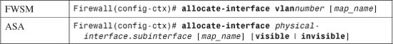
The physical subinterface named physical-interface.subinterface (ASA) or the Virtual LAN (VLAN) interface (FWSM) is mapped to the current context as an interface by the same name. You can include an arbitrary logical map_name if you want to keep the actual interface name hidden from the context users. In that case, the context users use map_name to further configure the interface.
You can also map a range of subinterfaces or VLAN interfaces, as long as their subinterface or VLAN numbers are contiguous. Use the following command to accomplish this mapping:
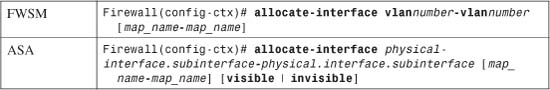
Specify the range of interfaces with the starting subinterface and the ending subinterface, separated by a hyphen. The physical interface name (physical-interface) must be identical in the range definition, with only the subinterface numbers changing. For example, the following command maps subinterface numbers 1 through 5:
Firewall(config-ctx)# allocate-interface
gigabitethernet0.1-gigabitethernet0.5
For the FWSM platform, the range is given with the starting and ending VLAN interfaces, each beginning with the keyword vlan followed by the VLAN number. For example, the following command maps interfaces for VLANs 1 through 5:
Firewall(config-ctx)# allocate-interface vlan1-vlan5
Naturally, you can also map a range of subinterfaces or VLAN interfaces to a range of logical interface names. To do so, specify the range of map names from starting to ending, separated by a hyphen. The map_name is an arbitrary name ending with a number. Both the starting and ending map_name must be identical, except for the number. The starting and ending number must define a range of the same size as the physical or VLAN interface range.
For example, you can allocate a range of five physical subinterfaces to a range of five logical names with the following ASA command:
Firewall(config-ctx)# allocate-interface
gigabitethernet0.1-gigabitethernet0.5 Int1-Int5
Similarly, you could use the following command on an FWSM platform:
Firewall(config-ctx)# allocate-interface vlan1-vlan5 Int1-Int5
Note
Although an interface can be mapped to other contexts, each context maintains its own interface state. For example, suppose physical interface GigabitEthernet0 has been mapped to interface0 in context admin. Context admin can shut down its interface0 while the physical interface GigabitEthernet0 is still up and functioning in the system execution space.
Naturally, the reverse is not true; the system execution space controls the interface state for all other contexts. If the system space has a physical interface administratively shut down (with the shutdown command), all other contexts with that interface mapped show it as simply “down” and not “administratively down.”
Also notice that, in the system space, interfaces are strictly physical and do not have logical names or security levels. You can see this in the following example:
Firewall# show interface
Interface GigabitEthernet0 "", is up, line protocol is up
Hardware is i82543 rev02, BW 1000 Mbps, Full-duplex
Description: Outside public network (non-trunk)
Available for allocation to a context
MAC address 0003.479a.b395, MTU not set
IP address unassigned
[output omitted]
Interface GigabitEthernet0.2 "", is up, line protocol is up
VLAN identifier 2
Description: VLAN 2 - inside private network
Available for allocation to a context
Interface GigabitEthernet0.3 "", is up, line protocol is up
VLAN identifier 3
Description: VLAN 3 - stateful failover
Available for allocation to a context
4. Define the context startup configuration location:
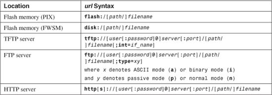
Firewall(config-ctx)# config-url url
The startup configuration can be located at a URL defined by url at any of the locations listed in Table 4-2.
Table 4-2 Context Startup Configuration Locations
Caution
As soon as you enter the config-url command, the system execution space attempts to load that configuration file immediately. This is done so that the new context can be built with a working configuration. If the URL points to a location external to the firewall, the IP connectivity configured on the admin context is used to reach the URL server.
However, be aware that if you reenter the config-url command to point to a new configuration file location, the configuration commands in that file are immediately merged with the context’s running configuration. This could result in an undesirable configuration.
Within the new context, the URL pointing to the configuration file is used in place of a startup configuration file in flash memory. If the configuration file does not yet exist, the firewall creates the file with a minimal or blank context configuration.
Any commands that involve the startup configuration use the URL instead. For example, the copy running-config startup-config and write memory commands copy the current running configuration to a file defined by the URL.
In this fashion, the startup configuration can be uploaded to or downloaded from the URL location. The only exception is a URL that points to an HTTP or HTTPS server; then the file can only be downloaded to the firewall context.
For example, the following commands configure the CustomerA context to download its startup configuration from a TFTP server:
Firewall(config)# context CustomerA
Firewall(config-ctx)# config-url tftp://192.168.200.10/pixconfigs/
CustomerA.cfg
Tip
You can name the configuration file with any arbitrary name, with or without a dotted suffix. Usually, it is a good idea to develop some sort of naming standard. For example, the filename might indicate the context name and a suffix of .cfg could be added to indicate that the file is a context configuration.
5. (Optional) Designate the admin context:
Firewall(config)# admin-context name
By default, the admin context is named “admin,” and the following command is automatically added to the system execution space configuration:
Firewall(config)# admin-context admin
If you would rather use the context you have just created as the admin context, you can use the preceding command to assign its new role. The previous admin context still exists in the system execution space configuration and as a working context.
Tip
You must store the admin context startup configuration file in the internal flash memory so that it is always accessible. Make sure you have defined the configuration file location as such:
Firewall(config-ctx)# admin-context adminFirewall(config-ctx)# config-url flash:/admin.cfg
If a context other than one called “admin” is configured as the admin context, the commands might appear as follows:
Firewall(config-ctx)# admin-context MainFirewall(config-ctx)# config-url flash:/Main.cfg
Context Definition Example
Consider a physical firewall that is configured with three separate contexts for the enterprise:
• One for firewall administration
• One for Department A
• One for Department B
Figure 4-7 shows a network diagram of the multiple-context arrangement.
Figure 4-7 Network Diagram of the Multiple-Context Example
For the purposes of this example, each context is defined and configured with only basic interface parameters. The idea is to become familiar with context creation and configuration and interface allocation. You perform the configuration steps by connecting to the physical firewall console to gain access to the system execution space.
First, get a sampling of the physical interfaces that are available on the system execution space. These interfaces are available to be mapped into user contexts. The following command and output are used:
Firewall# show running-config
: Saved
:
ASA Version 8.0(1) <system>
!
interface GigabitEthernet0/0
description Public interface
!
interface GigabitEthernet0/1
description Trunk for private context interfaces
!
interface GigabitEthernet0/1.2
vlan 2
!
interface GigabitEthernet0/1.3
vlan 3
!
interface GigabitEthernet0/1.4
vlan 4
[output omitted]
Next, the admin context is used for firewall management, so it must be defined in the system execution space configuration. The admin startup configuration is stored in flash as the file admin.cfg. Two firewall interfaces are allocated to the context. Because it is the admin context, the interface names cannot be mapped to other arbitrary names. Use the following commands to configure the admin context:
Firewall# configure terminal
Firewall(config)# context admin
Firewall(config-ctx)# config-url flash:/admin.cfg
Cryptochecksum(unchanged): 352c788c 39cd2793 66c6ef98 c6bc632e
INFO: Context admin was created with URL flash:/admin.cfg
INFO: Admin context will take some time to come up .... please wait.
Firewall(config-ctx)#
Firewall(config-ctx)# allocate-interface GigabitEthernet0/0
Firewall(config-ctx)# allocate-interface GigabitEthernet0/1.2
Firewall(config-ctx)# exit
Firewall(config-ctx)# admin-context admin
Firewall(config)#
Now you can define a user context called DepartmentA. This is also done from the system execution space. Two firewall interfaces are allocated to the context, and the names are mapped to the generic values intf0 and intf1. For the present time, the context startup configuration is stored as a file named DepartmentA.cfg in flash memory. You can manage this file from the system execution space only, but context users can read or write to it using the startup-config command keyword. Later, the context users can arrange to store the file on an external server. When that happens, the following config-url command needs to be updated:
Firewall(config)# context DepartmentA
Firewall(config-ctx)# config-url flash:/DepartmentA.cfg
WARNING: Could not fetch the URL flash:/DepartmentA.cfg
INFO: Creating context with default config
Firewall(config-ctx)# description Virtual Firewall for Department A
Firewall(config-ctx)# allocate-interface GigabitEthernet0/0 intf0
Firewall(config-ctx)# allocate-interface GigabitEthernet0/1.3 intf1
Firewall(config-ctx)# exit
Define the user context DepartmentB with the following commands on the system execution space. This context is structured similarly to the DepartmentA context. The startup configuration also is stored on the firewall flash until it is moved later.
Firewall(config)# context DepartmentB
Firewall(config-ctx)# description Virtual firewall for Department B
Firewall(config-ctx)# config-url flash:/DepartmentB.cfg
WARNING: Could not fetch the URL flash:/DepartmentB.cfg
INFO: Creating context with default config
Firewall(config-ctx)# allocate-interface GigabitEthernet0/0 intf0
Firewall(config-ctx)# allocate-interface GigabitEthernet0/1.4 intf1
Firewall(config-ctx)# exit
Firewall(config)# exit
Firewall#
After all the contexts are defined, do not forget to save the system execution space configuration to flash memory using the following command:
Firewall# copy running-config startup-config
At this point, the firewall flash memory contains the startup configuration files for every user context. (The system execution space startup configuration file is always stored in a hidden flash file system.) The firewall flash memory looks something like this:
Firewall# dir flash:/
Directory of flash:/
3 -rw- 4958208 06:41:52 Nov 30 2004 image.bin
4 -rw- 8596996 10:12:38 Nov 12 2004 asdm.bin
10 -rw- 1591 16:45:18 Dec 03 2004 old_running.cfg
12 -rw- 1853 09:47:02 Dec 30 2004 admin.cfg
14 -rw- 2119 14:16:56 Dec 07 2004 CustomerA.cfg
16 -rw- 2002 14:19:44 Dec 07 2004 CustomerB.cfg
16128000 bytes total (2565231 bytes free)
Firewall#
Note
Notice that the system execution space contains an Adaptive Security Device Manager (ASDM) image file (asdm.bin). Users in other contexts cannot directly access the flash file system, so those contexts cannot use the image file. However, users in each context can run ASDM sessions to manage the context. The firewall coordinates all this from the system execution space from a single ASDM image. As expected, context users can see and manage only their own context.
Now, each user context can be configured as an independent firewall. Each one starts with an empty configuration, except for the mapped interface definitions, so the initial session must be opened from the system execution space. As soon as a context is configured with enough information to have network connectivity, users can connect through any other means (Telnet, SSH, ASDM, and so on).
First, change the session to the admin context and have a look at the available interfaces. Notice that each one is present but has no usable configuration.
Firewall# changeto context admin
Firewall/admin# show running-config
:
PIX Version 8.0(1) <context>
names
!
interface GigabitEthernet0/0
no nameif
no security-level
no ip address
!
interface GigabitEthernet0/1.2
no nameif
no security-level
no ip address
[output omitted]
At a minimum, name the inside and outside interfaces, and configure them with IP addresses and security levels. You can do this with the following configuration commands (described in more detail in Chapter 3, “Building Connectivity”):
Firewall/admin# configure terminal
Firewall/admin(config)# interface GigabitEthernet0/0
Firewall/admin(config-if)# nameif outside
Firewall/admin(config-if)# security-level 0
Firewall/admin(config-if)# ip address 192.168.1.10 255.255.255.0
Firewall/admin(config-if)# no shutdown
Firewall/admin(config)# interface GigabitEthernet0/1.2
Firewall/admin(config-if)# nameif inside
Firewall/admin(config-if)# security-level 100
Firewall/admin(config-if)# ip address 192.168.2.1 255.255.255.0
Firewall/admin(config-if)# no shutdown
You can configure the DepartmentA and DepartmentB user contexts in a similar manner. Use the changeto context DepartmentA and changeto context DepartmentB commands to move the session to each context.
In this example, firewall interfaces are allocated to the user contexts with the mapped names intf0 and intf1. After you connect to a user context session, the only clue you have about a mapped interface is its generic or mapped name. After all, the idea behind mapping interfaces is to present context users with arbitrary interface names that do not represent physical hardware.
Therefore, you might have to return to the system execution space configuration to remember which physical firewall interface is mapped to which context interface and which context interface should be configured as inside and outside.
To continue the example, the DepartmentA user context is configured next. Notice the initial interface definitions:
Firewall/admin# changeto context DepartmentA
Firewall/DepartmentA# show running-config
: Saved
:
PIX Version 8.0(1) <context>
names
!
interface intf0
no nameif
no security-level
no ip address
!
interface intf1
no nameif
no security-level
no ip address
[output omitted]
Now you can configure the context interfaces with the following commands:
Firewall/DepartmentA# configure terminal
Firewall/DepartmentA(config)# interface intf0
Firewall/DepartmentA(config-if)# nameif outside
Firewall/DepartmentA(config-if)# security-level 0
Firewall/DepartmentA(config-if)# ip address 192.168.1.11 255.255.255.0
Firewall/DepartmentA(config-if)# no shutdown
Firewall/DepartmentA(config)# interface intf1
Firewall/DepartmentA(config-if)# nameif inside
Firewall/DepartmentA(config-if)# security-level 100
Firewall/DepartmentA(config-if)# ip address 192.168.3.1 255.255.255.0
Firewall/DepartmentA(config-if)# no shutdown
Tip
After you move your session to a different user context, it might be tempting to use the exit command to return to the previously visited context or the system execution space. Entering exit only terminates your session with the current context, requiring you to authenticate with it again so that you can use the changeto command.
Think of each context as having its own virtual console connection. By using the changeto command, you move the console connection from one context to another.
Allocating Firewall Resources to Contexts
When a firewall platform is running in single-context security mode, you can configure and use only one operational firewall. Therefore, that firewall can use any or all of the available traffic inspection and session resources on that hardware platform. In other words, if the firewall uses most of its own resources while it does its job, its own performance is not affected.
In multiple-context security mode, however, all the configured contexts must share the available resources on their physical firewall platform. If one context becomes heavily loaded or highly utilized, it can use a majority of the traffic inspection resources. This can affect the other contexts by leaving them starved for the same resources.
Multiple-context mode can support resource allocation by imposing limits on how specific resources are used. You can configure resource limits in classes according to the resource type and assign memberships in the classes to contexts. Resource allocation has the following characteristics:
• Resource allocation is available on the FWSM, starting with release 2.2(1). Resource allocation is also available starting with ASA 7.2(1).
• Firewall resources that can be limited fall into several categories:
— Stateful inspection—The number of hosts, connections, address translations, and application inspections
— MAC addresses—The number of MAC addresses learned in transparent firewall mode
— Syslog message generation rate—The number of logging messages sent per second to Syslog servers
— Administrative sessions—The number of ASDM, Telnet, SSH, and IPSec connections to the firewall
• The default class permits unlimited use of most resources for all contexts by default. You can configure the default class and adjust specific resource limits in it, if needed.
• You can define and configure new classes with resource limits tailored for a certain level of service.
• You can impose specific limits on a context by assigning it membership in a class. Otherwise, every context that is not a class member belongs to the default class.
• Limits are set per class, not per context. Therefore, all contexts that are assigned to a class share various resources up to the limits of that class. To configure limits on a per-context basis, define one class per context and assign each context to its respective class.
• To exercise thorough control over system resources, you should define classes with specific limits. Then make sure every context is assigned to a class. After that is done, no context can inherit the unlimited resources of the default class.
You can use the following steps to define and apply classes of resource limits to security contexts:
1. Define a class of service.
a. Identify the class:
Firewall(config)# class name
The class is named name (an arbitrary string up to 20 characters).
Tip
You can adjust the resource limits that are defined in the default class by using the class name default in this configuration step. The command syntax then becomes class default. By default, all the default class limits are set to unlimited (0), except for the following:
• ASDM sessions (the default is 5)
• Telnet sessions (the default is 5)
• SSH sessions (the default is 5)
• IPSec sessions (the default is 5)
• MAC addresses (the default is 65,535 entries)
b. (Optional) Define a limit for all resources:
Firewall(config-class)# limit-resource all number%
All resource types are limited to number (1 to 100) percent of the maximum available on the physical firewall platform. This limit overrides any resource types that are set in the class. After tnumber is set to 0, all resources are allowed to be unlimited. The value number must be followed by a percent character.
For example, to limit all resources to 50 percent of their possible values, you would use the following command:
Firewall(config-class)# limit-resource all 50%
c. (Optional) Define a limit for a single resource:
Firewall(config-class)# limit-resource [rate] resource_name number[%]
You can limit a specific firewall resource within the class. If you set a limit with this command, it overrides any limit set by the limit-resource all command or by the cific firewall.
You can limit the resource named resource_name to an actual value as number or to a percentage of the maximum possible value as number%. You can also add the rate keyword to indicate that number should be interpreted in units per second.
Use Table 4-3 to find resource names and their maximum values.
Table 4-3 Resource Names and Maximum Values

1. The FWSM can generate a sustained rate of 30,000 logging messages per second to a terminal session or the internal logging buffer. Sending messages to a Syslog server imposes additional packet overhead, reducing the actual rate to 25,000 messages per second.
Firewalls also support resource limits on various types of sessions that terminate on the firewall. Use Table 4-4 to find those resource names and maximum values.
Table 4-4 Resource Names and Maximum Values for Terminating Session Types
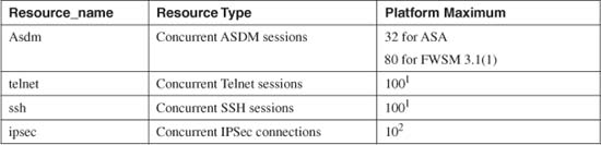
1. The FWSM can support up to 100 concurrent Telnet and SSH sessions over all contexts. It imposes a limit of five concurrent Telnet and five concurrent SSH sessions per context.
2. The FWSM can support up to ten concurrent IPSec connections over all contexts, or up to five concurrent connections per context.
You can repeat the limit-resource command to define other resource limits for the class. For example, a class called Silver is configured to limit all firewall resources to 25 percent of the maximum available resources. In addition, the number of xlates is limited to 50,000, and the number of conns is limited to 100,000. The number of Syslog messages is limited to 4000 per second. You can use the following commands to define these limits:
Firewall(config)# class Silver
Firewall(config-class)# limit-resource all 25%
Firewall(config-class)# limit-resource xlates 50000
Firewall(config-class)# limit-resource conns 100000
Firewall(config-class)# limit-resource rate syslogs 4000
d. Exit the resource class submode:
Firewall(config-class)# exit
2. Assign a context to a class.
a. Select a context:
Firewall(config)# context name
The context name should already be defined in the system execution space configuration.
b. Assign it to a resource class:
Firewall(config-ctx)# member class
The context becomes a member of the resource allocation class named “class,” as defined in Step 1. You can assign membership in only one user-defined class per context. Keep in mind that every context also belongs to the default class. Any resource limit that is not defined in “class” is then inherited from the default class.
3. Monitor resource allocation.
a. Display class membership:
Firewall# show class
Each of the configured classes is shown with its member contexts. In the following example, all contexts are members of the “default” class, and only context 1 is a member of the “silver” class:
Firewall# show class
Class Name Members ID Flags
default All 1 0001
silver 1 2 0000
Firewall#
b. Review resource allocation:
Firewall# show resource allocation [detail]
You can use this command to display the current breakdown of resource limits as percentages of the total available. Add the detail keyword to see a more detailed breakdown by resource and context, as in the following example:
Firewall# show resource allocation
Resource Total % of Avail
Conns [rate] 85000 50.00%
Fixups [rate] 50000 50.00%
Syslogs [rate] 15000 50.00%
Conns 500000 50.05%
Hosts 131072 50.00%
IPSec 5 50.00%
Mac-addresses 32767 49.99%
ASDM 5 6.25%
SSH 50 50.00%
Telnet 50 50.00%
Xlates 131072 50.00%
Firewall# show resource allocation detail
Resource Origin:
A Value was derived from the resource %and
C Value set in the definition of this class
D Value set in default class
Resource Class Mmbrs Origin Limit Total Total %
Conns [rate] default all CA unlimited
silver 1 CA 85000 85000 50.00%
All Contexts: 1 85000 50.00%
Fixups [rate] default all CA unlimited
silver 1 CA 50000 50000 50.00%
All Contexts: 1 50000 50.00%
Syslogs [rate] default all CA unlimited
silver 1 CA 15000 15000 50.00%
All Contexts: 1 15000 50.00%
Conns default all CA unlimited
silver 1 CA 500000 500000 50.05%
All Contexts: 1 500000 50.05%
[output truncated]
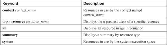
c. Display the current resource usage:
Firewall# show resource usage [context context_name | top n | all |
summary | system] [resource {[rate] resource_name | all} | detail] [counter counter_name
[count_threshold]]
You can use this command to display the actual resources being used, as described in Table 4-5.
Table 4-5 Options for Displaying Resources Being Used
You can also display the results for a specific resource by giving the resource keyword along with a resource_name.
Normally, each resource usage line is shown with the fields listed in Table 4-6.
Table 4-6 Resource Usage Line Fields
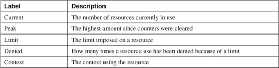
If you enter the counter keyword, you can display results based one of the following specific counter_name values: current, peak, denied, or all.
You can also get a feel for the complete variety and number of firewall resources used by a context. By adding the detail keyword, you can see all resources being used, whether or not the resources can be limited.
Verifying Multiple-Context Operation
To see the current admin context name and configuration URL, you can use the show admin-context command, as in the following example from an ASA platform:
Firewall# show admin-context
Admin: admin flash:/admin.cfg
Firewall#
To see information about the configured contexts, you can use the following command:
Firewall# show context [[detail] [name] | count]
You can specify a context name to see information about only that context. Otherwise, all the contexts are shown. Include the detail keyword to see a breakdown of each context resource, including the configuration URL and interface mappings.
The following example shows the output from an ASA that has three configured contexts: admin, CustomerA, and CustomerB.
Firewall# show context
Context Name Interfaces URL
*admin GigabitEthernet0 flash:/admin.cfg
GigabitEthernet1.1
CustomerA GigabitEthernet0, tftp://172.30.1.10/customerA.cfg
GigabitEthernet1.3
CustomerB GigabitEthernet1.2,3 tftp://172.16.0.20/customerB.cfg
Total active Security Contexts: 3
Firewall#
On an FWSM platform, the same command produces slightly different output:
Firewall# show context
Context Name Class Interfaces URL
*admin silver Vlan10,100 disk:/admin.cfg
CustomerA silver Vlan20,100 tftp://172.30.1.10/customerA.cfg
CustomerB default Vlan30,100 tftp://172.16.0.20/customerB.cfg
You can add the detail keyword to see a breakdown of the context configuration. The following example shows the detailed configuration for a context named CustomerA:
Firewall# show context detail CustomerA
Context "CustomerA", has been created
Desc: Virtual firewall for CustomerA's headquarters location
Config URL: tftp://172.30.1.10/customerA.cfg
Real Interfaces: GigabitEthernet0, GigabitEthernet1.3
Mapped Interfaces: intf0, intf1
Flags: 0x00000011, ID: 2
Failover group: 1
Firewall#
Finally, although the firewall cannot limit CPU load as a resource that is shared across contexts, the firewall does keep CPU load statistics. You can see a breakdown of the CPU usage as it is distributed across all the configured contexts. Use the following command from the system execution space:
Firewall# show cpu usage context {name | all}
The following example shows CPU usage on a firewall configured with three contexts:
Firewall# show cpu usage context all
5 sec 1 min 5 min Context Name
7.1% 8.0% 7.1% system
12.0% 12.0% 10.0% admin
27.7% 28.5% 27.0% CustomerA
4.0% 4.0% 4.0% CustomerB
Firewall#
4-2 Managing the Flash File System
Every Cisco firewall has a flash (nonvolatile) memory file system. Files such as the firewall operating system image, a firewall management application image, and the firewall configuration can be stored for use. This section discusses the various types of files and how to navigate and use the flash file system. The flash file system can be characterized by the following features:
• The operating system for Cisco firewalls is stored in flash memory in a compressed format. In PIX 6.3 or earlier, only one image can be stored in flash at any time. FWSM allows one image to be stored in each of two flash memory partitions, although only one image can be run at any time.
The ASA release loosens this restriction, allowing multiple images; however, only one of those images can run actively at any time.
• In ASA and FWSM multiple-context modes, only the system execution space can directly access and manage the flash file system. All other contexts have no knowledge of a flash file system and no means to manage one.
• When a firewall boots, it uncompresses and copies an executable image from flash to RAM. The image is actually run from RAM.
• While an image is being run, a different image can be copied or written into flash memory. In fact, the running image can be safely overwritten in flash, because it is run from RAM. The new image is not run until the next time the firewall reloads.
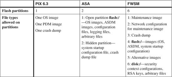
• The various Cisco firewall platforms have different flash memory organization and storage capabilities. Generally, flash memory is divided into partitions, each having its own restrictions on the types of files that can be stored there. Table 4-7 summarizes the flash memory differences:
Table 4-7 Flash Memory Organization/Storage by Platform
• The operating system and ASDM or PDM images must be compatible before ASDM/PDM can be used. An ASDM/PDM image can be loaded into flash at any time without requiring a firewall reload.
• An image (operating system or ASDM/PDM) can be transferred into a firewall by any of the following methods:
— TFTP at the monitor prompt
— TFTP from an administrative session (firewall console, Telnet, or SSH)
— HTTP or HTTPS from a web server
— The firewall polls an Auto Update Server (AUS) device periodically to see if a new image is available for it. If so, the image is downloaded using HTTPS (TCP port 443).
Tip
After an ASDM or PDM image is downloaded into the firewall flash memory, it can be used immediately. After an operating system image is downloaded, however, the firewall must be rebooted to run the new image. You have to manually force a reboot by using the reload EXEC command. Obviously, you can download a new OS image at any time—even while the firewall is in production. To run the new image, firewall service has to be interrupted during downtime or a maintenance window.
Navigating an ASA or FWSM Flash File System
ASA and FWSM platforms organize their flash file systems much like a traditional IOS file system, which must be formatted, and can contain a tree of directories, each containing arbitrary files. You can navigate the flash file system and manage any of its contents, as described in the following sections.
Tip
In ASA, you can use flash:/ to reference the entire flash file system.
FWSM, however, uses flash:/ to reference the flash partition that contains operating system and PDM images. You can use disk:/ to reference the flash partition that contains configuration files and other arbitrary files.
Each administrative session maintains a current placeholder or current directory where the user is positioned within the firewall file system. This is very similar to navigating a file system from within a shell on a Windows or UNIX machine.
In an administrative session, you can take the following actions:
• List the files stored in a directory:
![]()
By default, an administrative session begins in the flash:/ or disk:/ root directory, for ASA or FWSM, respectively. You can specify the flash: or disk: keyword and a path to view the contents of a different directory. The path also can contain regular expressions to match specific patterns within filenames.
For example, you can use the following command on an ASA to see a list of all configuration files (having a .cfg suffix) in flash:
Firewall# dir flash:*.cfg
Directory of flash:/*.cfg
10 -rw- 1575 23:05:09 Sep 30 2004 old_running.cfg
12 -rw- 3134 23:30:24 Nov 08 2004 admin.cfg
13 -rw- 1401 14:12:31 Oct 20 2004 CustomerA.cfg
14 -rw- 2515 23:29:28 Nov 08 2004 border.cfg
17 -rw- 1961 13:52:22 Oct 25 2004 datacenter.cfg
You can use the /all keyword to list all the files in the directory and the /recursive keyword to recursively look in all nested directories and list the files found.
• Display the current directory name:
![]()
Because you can “move around” within the flash file system hierarchy, it is easy to forget where the current directory is pointed. In the following example, the user has moved into the Syslog directory in flash:
Firewall# pwd
flash:/syslog/
• Change to a different directory:
![]()
You can specify a directory name as path relative to the file system’s root. The keyword flash: or disk: is optional but is the default. If the cd command is used alone, the pointer is changed to the root directory in flash.
For example, the following commands move the user into the Syslog directory in flash:
Firewall# cd
Firewall# cd syslog
or
Firewall# cd flash:/syslog
• Display a file’s contents:
![]()
The file found at filesystem:path is displayed, one page at a time, in the current administrative session. By default, the flash: or disk: file system is assumed, and the file contents are shown as plain text. For example, the following command displays the flash:/mytest text file:
Firewall# more mytest
hello this is a test
the end
Firewall#
You can also display a file to see both the hex and ASCII representations of its contents. The file can contain either ASCII text or binary data. You can use either the /binary or /ascii keyword, because they produce identical results. The following example shows the same small text file in the dual format:
Firewall# more /ascii mytest
00000000: 68656c6c 6f207468 69732069 73206120 hell o th is i s a
00000010: 74657374 0d0a0d0a 74686520 656e64XX test .... the endX
Firewall#
Tip
Be careful when you use the more command. If you attempt to view the contents of a large binary file, such as by using more image.bin to view the PIX image file, you could be stuck waiting a very long time while every byte is shown as a literal (and often cryptic) character to your terminal session. If you want to look at the contents of a binary file, always use the more /binary or more /ascii forms of the command.
Administering an ASA or FWSM Flash File System
An ASA platform offers two file systems—a flash file system that is accessible to administrative users, and a hidden file system that contains system-related resources that are inaccessible. On an FWSM platform, both file systems are accessible. The flash file system can contain files and directories, each under user control.
In an administrative session, you can take the following management actions on the flash file system and its contents:
• Copy a file to or from flash.
You can copy files according to the basic syntax copy from to, as in the following commands:
![]()
or
![]()
In the flash file system, files are identified by their path, relative to the flash root directory, and their filename. You can use regular expressions in the filename to select specific files if needed.
Files can be copied to or from a URL, which can be an FTP server, a TFTP server, or another location in flash. The respective URL formats are as follows:
ftp://[user[:password]@]server[:port]/[path/]filename[;type=xy]
tftp://[user[:password]@]server[:port]/[path/]filename
flash:path/filename
If a server requires user authentication, you can specify the user ID and password in the user:password@ format.
Tip
Prior to ASA 7.2(1), the URL required an IP address; the firewall could not resolve fully qualified domain names (FQDN). If you are running ASA 7.2(1) or later, the firewall can use DNS to resolve the IP address in a URL.
Make sure you use the following commands to configure DNS resolution on a specific firewall interface, the firewall’s default domain name, and one or more DNS addresses:
Firewall(config)# dns domain-lookup if_nameFirewall(config)# dns server-group nameFirewall(config-dns-server-group)# domain-name nameFirewall(config-dns-server-group)# name-server ip_addr [ip_addr2] [...] [ip_addr6]Firewall(config-dns-server-group)# retries numberFirewall(config-dns-server-group)# timeout secondsFirewall(config-dns-server-group)# exit
• Delete a file from flash:
![]()
The file named filename is deleted from flash. You can specify the flash: or disk: keyword, as well as a path, if needed. If those are omitted, the flash file system is assumed, and the path is assumed to be the current working directory (as shown by the pwd command).
You can use the /noconfirm keyword to delete the file without being asked to confirm the action. Without this keyword, you must press the Enter key each time the firewall prompts you for confirmation. You can delete an entire directory and its contents recursively by using the /recursive keyword.
For example, suppose an old configuration file oldconfig.cfg exists in flash. First, a directory is shown to find the correct filename, and then the file is deleted using the following commands:
Firewall# dir flash:
Directory of flash:/
6 -rw- 4902912 17:11:35 Nov 22 2004 image.bin
10 -rw- 1575 23:05:09 Sep 30 2004 oldconfig.cfg
23 -rw- 8596996 10:12:38 Nov 12 2004 asdm.bin
Firewall# delete flash:oldconfig.cfg
Delete filename [oldconfig.cfg]
Delete flash:/oldconfig.cfg? [confirm]
Firewall#
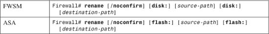
You can rename an existing file named source-path (a filename with an optional path) to destination-path. You can add the flash: or disk: file system keyword, but the flash memory is used by default. If you provide no other path information, the path is assumed to be the current working directory (as seen with the pwd command).
By default, the firewall prompts you for each argument as a confirmation. You can use the /noconfirm keyword to skip all the confirmation steps.
For example, the file flash:/capture1 is renamed flash:/capture2 using the following commands:
Firewall# rename flash:/capture1 flash:/capture2
Source filename [capture1]?
Destination filename [capture2]?
Firewall#
• Make a new directory:
![]()
A new empty directory is created at path, which can contain a path and filename. You can add the flash: or disk: keyword, but it is assumed by default. The firewall prompts you for confirmation before creating the directory. You can use the /noconfirm keyword to skip the confirmation prompts.
For example, to create a new directory called MyStuff in the flash file system, you would use the following command sequence:
Firewall# mkdir flash:/MyStuff
Create directory filename [MyStuff]?
Created dir flash:/MyStuff
Firewall# dir flash:
Directory of flash:/
[output omitted]
64 drw- 0 16:02:57 Nov 23 2006 MyStuff
16128000 bytes total (2419712 bytes free)
Firewall#
![]()
A directory named path is removed or deleted from flash. The path can contain a directory path and filename if needed. The firewall prompts you for confirmation before removing the directory. You can use the /noconfirm keyword to skip the confirmation prompts.
A directory must be empty of files and other directories before it can be removed.
• Check the flash file system’s integrity.
If you suspect that the flash file system might be corrupted, you can use the following command to check it:
![]()
The ASA flash file system has been checked in the following example. The output shows the number of orphaned files and directories that are found. These files and directories have been created but can no longer be reached in the file system because the mechanism to index or point to them is corrupt.
Firewall# fsck flash:
Fsck operation may take a while. Continue? [confirm]
flashfs[7]: 32 files, 6 directories
flashfs[7]: 0 orphaned files, 0 orphaned directories
flashfs[7]: Total bytes: 16128000
flashfs[7]: Bytes used: 13607936
flashfs[7]: Bytes available: 2520064
flashfs[7]: flashfs fsck took 23 seconds.
Fsck of flash:: complete
Firewall#
• Destroy the entire flash file system:
![]()
or
![]()
You should use the format and erase commands only in special cases, where the entire contents of flash memory (both accessible and hidden flash file systems) need to be erased. This might be desirable if a firewall is to be turned over or transferred to a different owner and the flash contents need to remain confidential.
Every file, including image files, configuration files, and licensing files, is overwritten with a 0xFF data pattern so that it is completely removed. A generic flash file system is then rebuilt.
Using the PIX 6.3 Flash File System
In PIX 6.3, the flash memory is organized as a “closed,” flat file system. Only six different files can be stored in flash. These files are not directly accessible or readable, and there is no hierarchical structure (folders or directories) to navigate. In fact, the files do not even have filenames. Instead, the firewall displays only the file index numbers it assigns automatically:
• 0—The operating system binary image.
• 1—The startup configuration commands; these are copied into the running configuration (RAM) and are executed when the firewall boots.
• 2—VPN and other keys and certificates.
• 3—The PDM image (if present).
• 4—A memory image saved after a firewall crash (if enabled).
• 5—The file size of the compressed operating system image (file 0).
In PIX 6.3, you can display the flash files with the show flashfs command, as in the following example:
Firewall# show flashfs
flash file system: version:3 magic:0x12345679
file 0: origin: 0 length:1949752
file 1: origin: 2097152 length:6080
file 2: origin: 2228224 length:1504
file 3: origin: 2359296 length:3126944
file 4: origin: 0 length:0
file 5: origin: 8257536 length:308
Firewall#
Identifying the Operating System Image
In PIX 6.3 and FWSM, only one operating system image file can be stored in flash at any time. The firewall automatically allocates storage for the image and handles its creation. In PIX 6.3, the image file is always indexed as file number 0 in the flash file system, as displayed by the show flashfs command. Therefore, when the firewall boots up, that image is always loaded into RAM and executed. In an FWSM, you can see a list of files in the image or application partition with the dir flash:/ command.
The ASA code platform relaxes this restriction, allowing one or more operating system images to be stored in flash, as long as there is sufficient space to store them. Naturally, only one of the image files can run on the firewall at any time, so you must select one file for use. Use the following command to select the bootable image:
Firewall(config)# boot system flash:filename
Naturally, this command is stored in the running configuration after it is entered. It should also be written into the startup configuration so that the image can be identified during the next reload or bootup. The firewall searches for the specified file as soon as the command is entered. If the file cannot be found in flash, the command is accepted but a warning message is displayed.
You can also enter this command more than once to configure a list of image files that can be executed. The list of filenames is tried in sequence so that if one file is not found in flash, the next file is tried, and so on.
The firewall also maintains this value as an environment variable BOOT while it is running. If multiple boot system commands have been configured, the BOOT variable contains the entire sequence of values. You can display the current boot image setting with the following command:
Firewall# show bootvar
For example, two image files are stored in flash: flash:/image.bin and flash:/image-beta.bin. You can run either image on the firewall. For normal production use, image.bin is used, whereas image-beta.bin is occasionally run to test new firewall features. The following commands show the available images and then specify image.bin and image-beta.bin as the bootable image sequence:
Firewall# dir flash:
Directory of flash:/
4 -rw- 4976640 10:23:28 Apr 1 2007 image.bin
9 -rw- 5261204 4:10:17 May 6 2007 image-beta.bin
[output omitted]
Firewall# configure terminal
Firewall(config)# boot system flash:/image.bin
Firewall(config)# boot system flash:/image-beta.bin
Firewall(config)# exit
Firewall# copy running-config startup-config
Firewall#
Firewall# show bootvar
BOOT variable = flash:/image.bin
Current BOOT variable = flash:/image.bin;flash:/image-beta.bin
CONFIG_FILE variable =
Current CONFIG_FILE variable =
Firewall#
Notice that the BOOT variable has two different lines of output. The first, BOOT variable, shows the value obtained from the boot system commands at bootup time. The Current BOOT variable line shows the current value obtained by any additional boot system commands entered since bootup.
Upgrading an Image from the Monitor Prompt
If the firewall has no operating system image, you can still download one via TFTP from the monitor prompt. At this point, the firewall is not inspecting any traffic and has no running configuration. Follow these steps to download a firewall operating system image via TFTP:
1. Make sure a TFTP server is available.
The TFTP server should have the firewall image available for downloading.
Tip
You can obtain TFTP server software from a variety of sources:
• Solarwinds.net TFTP server (http://www.solarwinds.net; free)
• Kiwi CatTools 2.x, Kiwi Enterprises (http://www.kiwisyslog.com; commercial package)
• Tftpd32 (http://tftpd32.jounin.net; free)
• tftpd, standard on UNIX systems (free)
At one time, Cisco offered a free TFTP server on Cisco.com. However, this was limited to Windows 95 installations, so it has since been dropped from support.
2. Boot the firewall to the monitor prompt.
Just after booting the firewall, you can press the Esc or Break key to break the normal bootup sequence. Be sure to do this when the following output and prompt are displayed:
Cisco Systems ROMMON Version (1.0(10)0) #0: Fri Mar 25 23:02:10 PST 2005
Platform ASA5510
Use BREAK or ESC to interrupt boot.
Use SPACE to begin boot immediately.
[The ESC key was pressed here]
Boot interrupted.
Management0/0
Ethernet auto negotiation timed out.
Interface-4 Link Not Established (check cable).
Default Interface number-4 Not Up
Use ? for help.
rommon #0>
Note
The parameters you assign here are used only temporarily until the firewall can download and run the new image. None of these commands is stored in a configuration; as soon as the firewall boots, they are lost.
a. Identify the firewall interface where the TFTP server is located:

On an ASA platform, you identify the interface by its physical interface name. For example, you could use ethernet0/0, ethernet0/1, ethernet0/2, ethernet0/3, or management0/0 on an ASA 5510.
TFTP on a PIX 6.3 platform uses the interface with index number (0 to n – 1, where n is the number of interfaces installed). During the bootup sequence, the firewall lists the physical interfaces that are installed. Some models also list their MAC addresses but do not number the interfaces. Therefore, it might not be clear how they correspond to the actual connections on the firewall. In any case, the first interface shown is always index 0.
Tip
On a PIX platform, when the installed interfaces are listed during bootup, only the interfaces that are not Gigabit Ethernet are shown. This is because you cannot use a Gigabit Ethernet interface to download a software image from the monitor prompt.
If you are stuck trying to figure out what interface names are available on an ASA, you can enter a bogus value for the interface name to get the valid names listed. For example, try something like interface 0 to get the following list:
rommon #1> interface 0
Invalid interface name argument, Valid arguments are:
Ethernet0/0
Ethernet0/1
Ethernet0/2
Ethernet0/3
Management0/0
interface <name> ethernet interface port
rommon #1>
b. Assign an IP address to the interface:
monitor> address ip-address
Here, the firewall needs just enough information to be able to contact the TFTP server. Only one physical interface can be used, so this IP address is applied to it. Because a subnet mask cannot be given, the firewall assumes a regular classful network mask (172.17.69.41 yields a Class B mask of 255.255.0.0, for example).
If your TFTP server is located on a different classful subnet, you can also specify a gateway address that can route between the firewall and the server. Use the following monitor command:
monitor> gateway ip-address
c. Make sure that the firewall can reach the TFTP server.
The firewall must be able to reach the server with a minimal amount of routing. You can use the following monitor command to test reachability:
monitor> ping ip-address
d. Define the TFTP server’s IP address:
monitor> server ip-address
e. Define the image filename to fetch:
monitor> file filename
The image file named filename is located in the TFTP server’s root directory. This is often called the /tftpboot directory, but it depends on how your TFTP server is configured. As long as the file can be found in the TFTP server’s root directory, you do not have to specify the directory name or path.
4. Copy the image from the TFTP server:
![]()
On an ASA, you should see exclamation points as the TFTP download is progressing. A successful TFTP download should look something like the following:
Cisco Systems ROMMON Version (1.0(10)0) #0: Fri Mar 25 23:02:10 PST 2005
Platform ASA5510
Use BREAK or ESC to interrupt boot.
Use SPACE to begin boot immediately.
Boot interrupted.
Management0/0
Ethernet auto negotiation timed out.
Interface-4 Link Not Established (check cable).
Default Interface number-4 Not Up
Use ? for help.
rommon #0> interface etherenet0/0
Ethernet0/0
Link is UP
MAC Address: 0016.c789.c8a4
rommon #1> address 172.17.69.1
rommon #2> server 172.17.69.49
rommon #3> ping 172.17.69.49
Sending 20, 100-byte ICMP Echoes to 172.17.69.49, timeout is 4 seconds:
!!!!!!!!!!!!!!!!!!!!
Success rate is 100 percent (20/20)
rommon #4> file image.bin
rommon #5> tftpdnld
ROMMON Variable Settings:
ADDRESS=172.17.69.1
SERVER=172.17.69.49
GATEWAY=0.0.0.0
PORT=Ethernet0/0
VLAN=untagged
IMAGE=image.bin
CONFIG=
LINKTIMEOUT=20
PKTTIMEOUT=4
RETRY=20
tftp [email protected] via 0.0.0.0
!!!!!!!!!!!!!!!!!!!!!!!!!!!!!!!!!!!!!!!!!!!!!!!!
[output omitted]
!!!!!!!!!!!!!!!!!!
Received 14487552 bytes
Launching TFTP Image...
Cisco Security Appliance admin loader (3.0) #0: Thu Mar 29 01:42:31 MDT 2007
Loading...
A PIX 6.3 platform will show periods or dots as the TFTP download is progressing. After the download completes, the firewall needs confirmation before it actually writes the new image into its flash memory. You can also enter a new license activation key at the end of this process, if needed.
A successful TFTP download looks something like this:
Cisco Secure PIX Firewall BIOS (4.0) #39: Tue Nov 28 18:44:51 PST 2000
Platform PIX-525
System Flash=E28F128J3 @ 0xfff00000
Use BREAK or ESC to interrupt flash boot.
Use SPACE to begin flash boot immediately.
Flash boot in 8 seconds.
[ESC key pressed here]
Flash boot interrupted.
0: i8255X @ PCI(bus:0 dev:14 irq:10)
1: i8255X @ PCI(bus:0 dev:13 irq:11)
Use ? for help.
monitor>
monitor> interface 0
Using 0: i8255X @ PCI(bus:0 dev:14 irq:10), MAC: 0090.2744.5e66
monitor> address 172.17.69.1
monitor> ping 172.17.69.49
Sending 5, 100-byte 0x5b8d ICMP Echoes to 172.17.69.49, timeout is 4
seconds:
!!!!!
Success rate is 100 percent (5/5)
monitor> server 172.17.69.41
monitor> file image.bin
monitor> tftp
tftp [email protected]...............................................
..........................................................................
[output omitted]
...............................................
Received 2064384 bytes.
Flash version 6.3(4), Install version 6.3(4)
Do you wish to copy the install image into flash? [n] y
Installing to flash
Serial Number: 807443449 (0x30209bf9)
Activation Key: c422440f 2eb1445a 46fb4413 74a344ee
Do you want to enter a new activation key? [n]
Writing 1941560 bytes image into flash...
5. Reload the firewall to run the new image:
monitor> reload
The firewall performs a reload immediately. You should see the usual bootup output on the console, followed by information about the new running image.
An ASA platform automatically reloads as soon as the code image TFTP download is finished.
Upgrading an Image from an Administrative Session
1. Make sure an image server is available.
The server should have the firewall image available for downloading, either by TFTP, FTP, HTTP, or HTTPS.
2. Make sure you have sufficient space on the flash file system.
An ASA allows one or more image files as well as other files to be stored in flash, as long as you have sufficient space to contain them all. When a new image or file is downloaded, it is stored in flash with a specific filename. A file is overwritten only if an existing file in flash has an identical filename.
You can use the following command to check the available (free) space in the flash memory:
Firewall# dir flash:/
For example, suppose a new firewall image is available on a server. The image file size is 4,995,512 bytes. First, the amount of free flash memory is checked, giving the following output:
Firewall# dir flash:/
Directory of flash:/
6 -rw- 4976640 10:04:50 Nov 12 2004 image.bin
10 -rw- 1575 23:05:09 Sep 30 2004 old_running.cfg
12 -rw- 3134 23:30:24 Nov 08 2004 admin.cfg
13 -rw- 1401 14:12:31 Oct 20 2004 CustomerA.cfg
14 -rw- 2515 23:29:28 Nov 08 2004 border.cfg
17 -rw- 1961 13:52:22 Oct 25 2004 datacenter.cfg
23 -rw- 8596996 10:12:38 Nov 12 2004 asdm.bin
21 drw- 704 15:06:09 Nov 22 2004 syslog
32 -rw- 205 15:06:08 Nov 22 2004 stuff
16128000 bytes total (2466816 bytes free)
Firewall#
Clearly, 2,466,816 bytes free is insufficient to store the new image unless the existing image (image.bin) is overwritten.
On an FWSM or a PIX 6.3 platform, only one operating system image and one PDM image can be stored in the flash file system at any time. If a new image is downloaded, it automatically overwrites an existing image in flash.
3. Make sure the firewall can reach the server:
Firewall# ping [interface] ip-address
The server has IP address ip-address. The firewall should already have the necessary routing information to reach the server. You can specify the firewall interface where the server is located (“outside,” for example) if the firewall cannot determine that directly. For example, this firewall can reach the server at 192.168.254.2:
Firewall# ping 192.168.254.2
Type escape sequence to abort.
Sending 5, 100-byte ICMP Echos to 192.168.254.2, timeout is 2 seconds:
!!!!!
Success rate is 100 percent (5/5), round-trip min/avg/max = 1/1/1 ms
Firewall#
4. (TFTP only) Identify a possible TFTP server:
Firewall(config)# tftp-server interface ip-address path
The TFTP server can be found at ip-address on the firewall interface named interface (outside), for example. As of FWSM 3.1(1) and ASA 7.0(1), the interface parameter is required. For prior releases, the firewall always assumes the inside interface is used for TFTP. The only way to override this assumption is by specifying a firewall interface in the tftp-server command. This interface is always used whenever files are copied to and from a TFTP server, even if the server address is different from the one configured with this command.
The image files are stored in the path directory on the TFTP server. This path is relative only to the TFTP process itself. For example, if the image files are stored in the topmost TFTP directory (/tftpboot within the server’s file system, for example), the path would be /, or the root of the TFTP directory tree.
Tip
The tftp-server command is optional because most of the TFTP parameters can be given with the copy EXEC command when the image is downloaded.
5. Copy the image file from the server.
With any download method, the basic command syntax is:
Firewall# copy source flash:[image | pdm | filename]
The image is downloaded and copied into flash memory as either an operating system image or a pdm image. Only one of either image type can be stored in the firewall flash, and their locations are automatically determined. In fact, PIX 6.3 restricts the image transfer to these two file types.
ASA and FWSM platforms make use of their more flexible flash file systems. From the system execution space, you can copy one or more image files into flash and then specify which image the firewall should use. You can give the destination filename as an arbitrary filename. You also can use the image or asdm keywords for backward compatibility. In that case, the firewall uses the image filename configured with the boot system or asdm image commands, respectively.
Also, you can choose TFTP, FTP, or HTTP as the copy method, as discussed in the following steps.
a. Use a TFTP server:
Firewall# copy tftp:[:[[//location][/pathname]] flash:[image | pdm |
filename]
The image file is located on the TFTP server at location, which can be either a hostname (already defined with a name command) or an IP address. The image file is referenced by pathname, which can include any directory structure needed within TFTP, along with the filename. (If the actual path name of the TFTP directory contains spaces, you should first define the whole path name using the tftp-server command. Spaces are not allowed in the pathname here.)
If the location or pathname parameters are left out of this command, the firewall prompts you for those values.
If you add a colon after the tftp keyword, the firewall picks up the remaining parameters configured with the tftp-server command.
For example, suppose a new operating system image named newimage.bin is located on TFTP server 192.168.254.2. Recall that the firewall assumes that the TFTP server is located on the inside interface by default. In this case, it is located on the outside interface. You can download the new firewall image into flash memory using the following commands:
Firewall# configure terminal
Firewall(config)# tftp-server outside 192.168.254.2 /
Firewall(config)# exit
Firewall# copy tftp://192.168.254.2/newimage.bin flash:image
Address or name of remote host [192.168.254.2]?
Source filename [newimage.bin]?
Destination filename [image.bin]?
%Warning:There is a file already existing with this name
Do you want to over write? [confirm]
Accessing tftp://192.168.254.2/newimage.bin...!!!!!!!!!!!!!
[output omitted]
Writing file flash:/image.bin...
!!!!!!!!!!!!!!!!!!!!!!!!!!!!!!!!!!!!1
4976640 bytes copied in 143.380 secs (34801 bytes/sec)
Firewall#
b. Use an FTP server:
Firewall# copy ftp://[user[:password]@]server[:port]/[path/]filename
[;type=xy] flash:[image | pdm | filename]
The FTP server is known as server by either an IP address or a hostname (the host name must be preconfigured with the name configuration command). If the server requires user authentication, the username and password are given as user:password@. By default, TCP port 21 is used; you can override this by specifying port.
The image file is found on the server with pathname path (relative to the user’s home directory) and filename filename. By default, the firewall uses an FTP session in binary passive mode. You can use a different FTP mode by appending the ;type=xy keyword, where x is a single letter a (ASCII) or i (image or binary) and y is a single letter p (passive) or n (normal). For example, ;type=ip is the default binary passive mode.
As an example, suppose an image named newimage.bin is located on an FTP server at 192.168.254.2. The server requires authentication using username myuserid and password mypassword, and the image is stored in the Images directory. You can download the new firewall image into flash memory using the following command:
Firewall# copy ftp://myuserid:[email protected]/Images/
newimage.bin flash:image
Address or name of remote host [192.168.254.2]?
Source filename [newimage.bin]?
Destination filename [image.bin]?
%Warning:There is a file already existing with this name
Do you want to over write? [confirm]
Accessing ftp://myuserid:[email protected]/Images/newimage.bin...
!!!!!!!!!!!!!
[output omitted]
Writing file flash:/image.bin...
!!!!!!!!!!!!!!!!!!!!!!!!!!!!!!!!!!!!1
4976640 bytes copied in 149.110 secs (33375 bytes/sec)
Firewall#
c. Use an HTTP or HTTPS server:
Firewall# copy http[s]://[user:password@]location[:port ]/
http_pathname flash[:[image | pdm | filename]
You can use either http (HTTP, port 80) or https (HTTPS or SSL, port 443), depending on how the web server is configured.
If user authentication is required, it can be given as user:password@. The web server has a name or IP address given by location. (If a host name is used, it must also be defined in the firewall with the name command.) By default, the port number is either TCP 80 or TCP 443, according to the http or https keyword. You can override the TCP port number by giving it as port.
The image file can be found on the server at the path http_pathname. The directory hierarchy is relative to the web server’s file structure.
For example, a PIX operating system image named newimage.bin is stored on the web server at http://192.168.254.2 in the default directory. The server requires authentication using username myuserid and password mypassword. You can download the new firewall image into flash memory using the following command:
Firewall# copy http://myuserid:[email protected]/newimage.bin flash:image.bin
Address or name of remote host [192.168.254.2]?
Source filename [newimage.bin]?
Destination filename [image.bin]?
%Warning:There is a file already existing with this name
Do you want to over write? [confirm]
Accessing http://192.168.254.2/newimage.bin...!!!!!!!!!!!!!!!!!
[output omitted]
Writing file flash:/image.bin...
!!!!!!!!!!!!!!!!!!!!!!!!!!!!!!!!!
[output omitted]
4902912 bytes copied in 137.730 secs (35787 bytes/sec)
Firewall#
Upgrading an Image Automatically
You can also configure a firewall to automatically poll a central server to see if a new image file exists. If a newer image is available, the firewall downloads it without any intervention on your part. This functionality is available with an Auto Update Server (AUS) and is discussed in detail in Section “4-4: Automatic Updates with an Auto Update Server.”
4-3 Managing Configuration Files
A firewall keeps a “startup” configuration file in flash memory. These configuration commands are not lost after a reload or power failure.
As soon as a firewall boots up, the startup configuration commands are copied to the “running” configuration file in RAM (volatile) memory. Any command that is entered or copied into the running configuration is also executed at that time.
As you enter configuration commands, be aware that they are present only in the temporary running configuration. After you have verified the operation of the new configuration commands, you should be sure to save the running configuration into flash memory. This preserves the configuration in case the firewall reloads later.
You can enter configuration commands into the firewall using the following methods:
• Command-line interface (CLI), where commands are entered through a console, Telnet, or SSH session on the firewall. The configure terminal command is used for this.
• A management application such as PDM or Firewall Management Center (within VMS).
• Imported by a TFTP file transfer.
• Imported by a web server.
• An automated or forced update from an AUS.
Managing the Startup Configuration
In PIX releases 6.3 and earlier, as well as FWSM releases, a firewall has one startup configuration that is stored in flash memory. This configuration file is read upon bootup and is copied into the running configuration.
ASA platforms running 7.0 or later have the capability to maintain one or more startup configuration files in flash, provided that you have sufficient space to store them. Only one of these can be used at boot time.
This section discusses the tasks that can be used to maintain and display the startup configuration file.
Selecting a Startup Configuration File
In ASA platforms, having multiple startup configurations makes configuration rollback easy. The startup configuration contents can be saved in one file during the time that the firewall configuration is stable. If major configuration changes need to be made, the new updated running configuration can be saved to a new startup configuration file. The next time the firewall is booted, it can use this new file.
If you encounter problems with the new configuration, you can make one configuration change to force the firewall to roll back or use a previous version of the startup configuration.
By default, a firewall stores its startup configuration in a hidden partition of flash memory. That file has no usable name and can be viewed only through the show startup-configuration command.
To force the firewall to use a different startup configuration filename, you can use the following command:
Firewall(config)# boot config url
url represents the location of the startup configuration file. It can be flash:/path, disk0:/path, or disk1:/path, depending on which flash file systems the firewall platform supports. PIX models have only a flash:/ file system, whereas the ASA platforms can support flash or disk flash file systems.
Be aware that the boot config url command effectively changes an environment variable used only by the running configuration. When you use this command, be sure to save the running configuration with the copy running-config startup-config or write memory command.
At this point, the firewall uses the new url and saves the startup configuration in that file, not in the default location. If the file does not exist, a new file is created; if it does exist, the running configuration is merged with that file’s contents. The environment variable is also updated and is used during the next boot cycle to find the new startup configuration file.
You can see the startup configuration environment variable with the show bootvar command. The following example begins with the default location, signified by the empty Current CONFIG FILE variable value. When the boot config command is used, the current value is updated to show the new file location.
However, until the running configuration is saved to the new startup configuration location, the new file is not present in flash. As well, the startup configuration file used at boot time is still the default (shown by an empty CONFIG FILE variable line). After the configuration is saved, the new file is used during the next firewall boot.
Firewall# show bootvar
BOOT variable = flash:/image.bin
Current BOOT variable = flash:/image.bin
CONFIG_FILE variable =
Current CONFIG_FILE variable =
Firewall# configure terminal
Firewall(config)# boot config flash:/startup-1.cfg
INFO: Converting myconfig.cfg to flash:/startup-1.cfg
Firewall(config)# exit
Firewall# show bootvar
BOOT variable = flash:/image.bin
Current BOOT variable = flash:/image.bin
CONFIG_FILE variable =
Current CONFIG_FILE variable = flash:/startup-1.cfg
Firewall# dir flash:/
Directory of flash:/
6 -rw- 5031936 10:21:11 Dec 21 2006 image.bin
23 -rw- 8596996 10:12:38 Nov 12 2006 asdm.bin
16128000 bytes total (2450944 bytes free)
Firewall#
Firewall# copy running-config startup-config
Source filename [running-config]?
Cryptochecksum: a8885ca7 9782e279 c6794487 6480e76a
3861 bytes copied in 0.900 secs
Firewall# show bootvar
BOOT variable = flash:/image.bin
Current BOOT variable = flash:/image.bin
CONFIG_FILE variable = flash:/startup-1.cfg
Current CONFIG_FILE variable = flash:/startup-1.cfg
Firewall# dir flash:/
Directory of flash:/
6 -rw- 5031936 10:21:11 Dec 21 2006 image.bin
23 -rw- 8596996 10:12:38 Nov 12 2006 asdm.bin
20 -rw- 3861 23:12:20 Dec 30 2006 startup-1.cfg
Finally, notice that even though a new location and a new filename are used for the startup configuration, you do not have to specify those when you save the running configuration later. The firewall continues to work with the startup-config keyword, but it uses the new url to reference the actual file. In other words, copy running-config startup-config always uses the current and correct location.
Displaying the Startup Configuration
You can display the contents of the startup configuration with either of these commands:
Firewall# show startup-config
or
Firewall# show configuration
In PIX 6.3, the latter command is actually show configure.
In the first line of the startup configuration, you can find its time stamp. This shows when the running configuration was saved to flash the last time and who saved it. For example, the generic user enable_15 (someone in privileged EXEC or enable mode) saved this configuration:
Firewall# show startup-config
: Saved
: Written by enable_15 at 17:41:51.013 EST Mon Nov 22 2006
PIX Version 8.0(1)
names
!
interface Ethernet0
shutdown
[output omitted]
Saving a Running Configuration
You can view or save a firewall’s running configuration with one of the methods described in the following sections.
Viewing the Running Configuration
You can use the following commands to display the current running configuration:
Firewall# write terminal
or
Firewall# show running-config
The running configuration is displayed to the current terminal session. If the configuration is longer than your current session page length (24 lines by default), you have to press the spacebar to page through it.
However, in ASA, FWSM, and PIX 6.3 platforms, you can filter the output by using one of the following keywords at the end of the command:
Firewall# show running-config | {begin | include | exclude | grep [-v]} reg-exp
You can start the first line of output at the line where the regular expression reg-exp appears in the configuration with the begin keyword.
If you are looking for lines that contain only the regular expression reg-exp, use the include or grep keyword. You can also display only the lines that do not contain the reg-exp with the exclude or grep -v keyword.
The regular expression can be a simple text fragment or a more complex form containing wildcard and pattern-matching characters. For example, include int finds any line that contains “int” (including words such as “interface”) located anywhere in the text.
These options are very handy if you have a firewall with a large configuration. Rather than paging through large amounts of configuration output, you can instantly find what you are looking for.
Saving the Running Configuration to Flash Memory
After you make configuration changes to a firewall and they are satisfactory, you should make them permanent by saving the running configuration to flash memory. You can use the following command to accomplish this:
Firewall# write memory
All the current configuration commands are stored in the startup configuration area in flash memory. You should always run this command after making configuration changes. Otherwise, you might forget to save them later when the firewall is reloaded.
In ASA and FWSM, the write memory command is supported for backward compatibility. A new form of the copy command is also provided, using the following syntax:
Firewall# copy running-config startup-config
Tip
In multiple context mode, each context’s running configuration must be saved individually. This usually means you have to move into each context with the changeto command and then use the write memory or copy running-config startup-config command.
Beginning with ASA 7.2(1) and FWSM 3.1(1), you can save all context configurations with a single command. In the system execution space, use the following command:
Firewall# write memory all
The copy command does not have the same capability.
When the configuration is saved or displayed, the firewall also displays a cryptochecksum, or a message digest 5 (MD5) hash of the configuration file contents. This value serves as a type of fingerprint that can be used to evaluate the configuration file’s integrity. The configuration file’s size is also shown, as in the following example:
Firewall# copy running-config startup-config
Source filename [running-config]?
Cryptochecksum: 71a4cecb 97baf374 10757e38 a320cc43
2909 bytes copied in 0.520 secs
Firewall#
Tip
You can use the MD5 cryptochecksum value as a quick check to see if a firewall’s configuration has changed since it booted. First, find the MD5 hash that was saved with the startup configuration by looking at the last line of the show startup-config or show config command. Then compare that to the MD5 hash of the current running configuration, shown in the last line of the show running-config command or with the output of the show checksum command. If the two hash values differ, the configuration has changed.
Comparing the two cryptochecksum values in the following example shows that the configuration has been changed:
Firewall# show startup-config | include checksum
Cryptochecksum:3750a83d00922b80ffef78e92865b09a
Firewall# show running-config | include checksum
Cryptochecksum:a5bdac82909dc8717e494cfabc2d363d
Firewall#
Saving the Running Configuration to a TFTP Server
You can use the following steps to save the current running configuration to an external file server:
1. (Optional) Identify the TFTP server:
Firewall(config)# tftp-server [interface] ip-address path
The TFTP server can be found on the firewall’s interface at IP address ip-address. By default, the inside interface is assumed. The running configuration file is stored in the path directory on the TFTP server. This path is relative only to the TFTP process itself. For example, if the file is stored in the topmost TFTP directory (/tftpboot, for example), the path would be /, or the root of the TFTP directory tree.
Tip
The tftp-server command is not necessary, because all the TFTP parameters can be given with the write net or copy EXEC command when the configuration is saved. However, the firewall always assumes the inside interface will be used for TFTP. The only way to override this assumption is by specifying a firewall interface (inside or outside, for example) in the tftp-server command. This interface is always used whenever files are copied to and from a TFTP server, even if the server address is different.
2. Save the configuration:
Firewall# write net [[server-ip-address]:[filename]]
The TFTP server can be identified by giving its IP address here as server-ip-address. The configuration is saved in a file named filename in the TFTP root directory on the server.
If the server is not specified here, the values configured by the tftp-server command are used. You can also override the server address configured with the tftp-server command by specifying an address here.
ASA and FWSM platforms also offer the copy command, which can be used to copy the running configuration to a TFTP server. You can use the following command:
Firewall# copy running-config
tftp://[user[:password]@]server[:port]/[path/]filename
Here, the running configuration is copied as a file with the filename filename. You can provide a path to specify where the file should be stored on the server. The path is relative to the TFTP server’s root directory. If the server requires user authentication, the user ID and password can be given in the form user:password@.
For example, the running configuration is to be saved as the file firewall.confg on the TFTP server at 192.168.208.40, located on the firewall’s dmz interface. The following commands can be used to accomplish this:
Firewall(config)# tftp-server dmz 192.168.208.40 /
Firewall(config)# exit
Firewall# write net 192.168.208.40:firewall.confg
or
Firewall# copy running-config tftp://192.168.208.40/firewall.confg
Forcing the Running Configuration to Be Copied Across a Failover Pair
During the bootup sequence, the active firewall copies its complete running configuration to the standby firewall. The active unit also copies any configuration commands to the standby unit as they are entered and executed.
Under normal conditions, the standby unit can keep its running configuration up to date and synchronized with the active unit. Sometimes it is possible for the two units to become unsynchronized. This can occur when configuration changes are made while the failover cable is disconnected, while the LAN-based failover connection is broken, or while the two units are running different OS releases. In these cases, you might see some of the logging messages in Table 4-8 generated when stateful failover cannot synchronize the two firewall units.
Table 4-8 Logging Messages Resulting from Stateful Failover Synchronization Errors
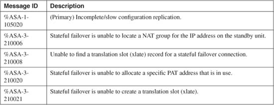
If you make configuration changes on the standby firewall unit, those changes are not replicated back toward the active unit. Instead, you see the following message:
*** WARNING ***
Configuration Replication is NOT performed from Standby unit to Active unit.
Configurations are no longer synchronized.
If you find that the running configurations are no longer identical and synchronized between the active and standby units, you can use the following command on the active unit to force a complete copy to be sent to the standby unit:
Firewall# write standby
Forcing the Startup (Nonvolatile) Configuration to Be Cleared
Sometimes you might need to begin with an empty configuration on a firewall. This might happen if you reuse an existing firewall in a different scenario or if you inherit a firewall from someone else.
The following command erases all configuration commands from the startup configuration in flash memory:
Firewall# write erase
This command does not disturb or erase the current running configuration. After the startup configuration is erased, you can use the reload EXEC command to reboot the firewall with the new, empty startup configuration.
Importing a Configuration
You can copy configuration commands into a firewall’s running configuration with one of the methods documented in the following sections.
Entering Configuration Commands Manually
You can begin entering configuration commands in a terminal session (console, Telnet, or SSH) after you use the following command:
Firewall# configure terminal
Commands are entered into the running configuration in RAM and are executed as they are entered. To end configuration mode, press Ctrl-z or enter exit.
Tip
In a failover pair of firewalls, configuration commands should be entered only on the active unit. As you enter configuration commands into the active unit, they are copied to the standby unit. Therefore, the failover configurations are automatically synchronized.
If you enter configuration commands on the standby unit, they are not replicated to the active unit. Therefore, the firewall configurations become different and are unsynchronized.
Merging Configuration Commands from Flash Memory
The commands stored in the startup configuration in flash memory can be copied over and merged into the running configuration after you issue the following command:
Firewall# configure memory
This is useful when the running configuration has been mistakenly cleared or the wrong configuration has been imported.
In ASA and FWSM platforms, you can achieve the same results with the following command:
Firewall# copy startup-config running-config
Tip
Remember that configuration commands are merged from flash into RAM. This means that commands in the running configuration are preserved, and the commands stored in flash are copied into the running configuration in RAM.
If similar commands are stored in both the startup and running configurations, the startup commands overwrite the others. In effect, this can result in a running configuration that is a mixture of startup and running configurations. It is a common misconception that the running configuration is erased before the startup configuration is copied onto it.
To erase the running configuration before the merge, use the clear configure all configuration command first. However, be aware that any existing configuration commands that provide IP addressing, routing, and administrative access are removed immediately. Unless you are connected to the firewall console, you could find that you become cut off from the newly cleared firewall.
Merging Configuration Commands from a TFTP Server
You can use the following steps to merge configuration commands from a file contained on an external TFTP server:
1. (Optional) Identify the TFTP server:
Firewall(config)# tftp-server [interface] ip-address path
The TFTP server can be found on the firewall’s interface at IP address ip-address. By default, the inside interface is assumed. The configuration file is copied from the path directory on the TFTP server. This path is relative only to the TFTP process itself. For example, if the file is stored in the topmost TFTP directory (/tftpboot, for example), the path would be simply a forward slash, as /, denoting the root of the TFTP directory tree.
2. Fetch and merge the configuration:
Firewall(config)# configure net [[server-ip-address]:[filename]]
The TFTP server can be identified by giving its IP address here as server-ip-address. The configuration is retrieved from the file named filename in the TFTP root directory on the server.
If the server is not specified here, the values configured by the tftp-server command are used. You can also override the server address configured with the tftp-server command by specifying an address here.
Although the ASA and FWSM support the legacy configure net command, they also offer the following new form of the copy command to achieve similar results:
Firewall# copy tftp://[user[:password]@]server[:port]/[path/]filename
running-config
Here, the file named filename is found at path on the TFTP server at IP address server. If the server requires user authentication, you can give the user ID and password using the user:password@ format.
Merging Configuration Commands from a Web Server
If you have a configuration file stored on an external web server, you can use the following command to merge its contents with the running configuration:
Firewall(config)# configure http[s]://[user:password@]location[:port]/
http-pathname
You can use either the http (HTTP, port 80) or https (HTTPS or SSL, port 443) protocol to transfer the configuration file, depending on how the web server is configured.
If user authentication is required, it can be given as user:password@. The web server has a name or IP address given by location. (If a host name is used, it must also be defined in the firewall with the name command.) By default, the port number is either 80 or 443, according to the http or https keyword. You can override the port number by giving it as port.
The configuration file can be found on the server at the path http-pathname. The directory hierarchy is relative to the web server’s file structure.
ASA and FWSM platforms also offer the following form of the copy command that achieves similar results:
Firewall# copy http[s]://[user[:password]@]server[:port]/[path/]filename
running-config
For example, suppose a configuration file named fwtemplate.cfg is stored on the web server at 172.30.22.17. User authentication is required, using user ID fwadmin and password myadminpw. You can use the following commands to merge the file with the running configuration:
Firewall# configure https://pixadmin/[email protected]/pixtemplate.cfg
or
Firewall# copy https://fwadmin/[email protected]/fwtemplate.cfg
running-config
Merging Configuration Commands from an Auto Update Server
You can use an Auto Update Server (AUS) as a platform to automatically merge a stored configuration file with the running configuration. Having the firewall pick up a new configuration file update is easier than a manual method if you have many firewalls to maintain.
The AUS feature is discussed in detail in the next section of this chapter.
4-4 Automatic Updates with an Auto Update Server
With an AUS, you can use one central location as a distribution point for the firewall image and configuration updates. This can be handy if you have many firewalls to maintain.
Ordinarily, you would have to manually transfer a new image or configuration file to each firewall individually. With AUS, each firewall can poll periodically to see if a new file is available. If a newer file is found, the firewall automatically downloads it without any further intervention.
A firewall can be configured to act as an Auto Update client, where it polls a central Auto Update Server for updates. ASA and PIX platforms can poll an AUS beginning with release 7.0(1); FWSM can poll an AUS beginning with release 3.1(1).
Traditionally, only specialized network management applications could operate as Auto Update Servers. These include Cisco Security Manager (CSM), Cisco VPN/Security Management Solution (VMS), and Resource Manager Essentials (RME, a part of CiscoWorks). Beginning with ASA 7.2(1), you can also configure an ASA platform to act as an AUS.
Configuring a Firewall as an Auto Update Client
Use the following steps to configure a firewall as an Auto Update client, so that it can periodically poll an AUS for new image and configuration files.
1. Make sure an AUS is available.
The firewall should be defined in the AUS, and the new image or configuration file should be assigned to or associated with it.
As soon as you load an image or configuration file into the AUS and associate it to a firewall, the firewall client can download and begin using the file the very next time it polls AUS. The client firewall checks to see if the file is newer than the one it is currently running. If so, it automatically downloads that file.
Be aware that when a client firewall downloads an updated operating system image file from an AUS, it automatically reloads itself so that it can begin running the new image. The reload happens immediately, with little or no warning!
In some circumstances, the AUS administrator can force AUS to send the firewall a request to download the configuration immediately—regardless of the AUS polling schedule.
2. Make sure the AUS can be reached:
Firewall# ping [interface] ip-address
Here, the AUS has IP address ip-address. The firewall should already have the necessary routing information to reach the AUS device. You can specify a firewall interface (“outside,” for example) where the AUS can be found if the firewall cannot determine that directly.
3. Identify the image and ASDM files to update.
If the firewall polls an AUS and finds a newer file to download, it has to know where it should store the files. For a configuration file, the firewall simply merges the newer configuration file into its running configuration.
However, operating system and ASDM image files must be stored in the firewall’s flash memory with specific filenames. You should define the image file locations and names with the following configuration commands:
Firewall(config)# boot system device:/filename
Firewall(config)# asdm image device:/filename
For example, if your firewall is running an image called image.bin and an ASDM image called asdm.bin, located in the flash filesystem, you could use the following commands:
Firewall(config)# boot system flash:/image.bin
Firewall(config)# asdm image flash:/asdm.bin
If the file locations are not configured at all, the firewall does not attempt to download new files from the AUS. Instead, it aborts the update and creates log message 612002, “Auto Update failed: Flash open failed.”
Tip
You should keep your operating system and ASDM image filenames as generic as possible. In other words, do not include the release number in the filename. The Auto Update process downloads new files right onto the location of existing files, reusing the original filenames.
If you keep the names generic, then a file called flash:/image.bin will always contain the up-to-date image. However, if you use a filename like flash:/asa801.bin, it might contain ASA release 8.0(1) today, but it might also contain ASA release 8.0(2) tomorrow. The filename is completely arbitrary, but it can become confusing to you if you use the name as an indicator of the release level.
4. Give the firewall an identity:
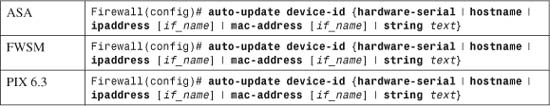
When an Auto Update client firewall polls the AUS, the AUS must be able to determine which files are associated with that firewall. After all, the AUS might be managing image and configuration files for many different firewalls in your organization.
You can choose how the firewall is identified to AUS with one of the following device ID methods:
• Host name (hostname)—The name set by the hostname configuration command is used. This is the default device ID.
• Firewall serial number (hardware-serial)—The number shown in the show version EXEC command is used.
• Interface IP address (ipaddress)—The address of the interface named if_name is used.
• Interface MAC address (mac-address)—The address of the interface named if_name is used.
• Text string (string)—The arbitrary alphanumeric string text is used. This can be useful when none of the other device ID options is relevant in your environment.
When a firewall device is configured in the AUS, it must also be uniquely identified with one of these methods. Make sure that the device ID configured in the auto-update device-id command matches the device ID configured in the AUS; otherwise, no files will be automatically updated between the AUS and the firewall.
Tip
Even though the client firewall is configured with a device ID, it also sends other information about itself. For example, the hardware platform family (ASA, PIX, or FWSM) and the specific model number are sent to the AUS.
With this information, the AUS can offer the files that are appropriate for the device family, the hostname, serial number, MAC address, and so on.
5. (Optional) Set the polling schedule.
Choose one of the methods described in Steps 5a and 5b to set the schedule when the firewall polls the AUS. You can set a regular polling interval with auto-update poll-period or a specific time schedule with auto-update poll-at command. However, you cannot configure both methods.
Caution
As you configure the polling schedule, keep in mind that the client firewall automatically reloads itself after a new operating system image is downloaded. Make sure you choose polling times where a reload and loss of traffic is acceptable—perhaps during a regular maintenance window or during regular periods of low traffic volume or impact.
a. Define the AUS polling period:

The firewall polls the AUS every poll-period minutes (the default is 720 minutes, or 12 hours). If an AUS connection fails, the firewall can retry the connection retry-count times (the default is 0—no retries). If the retry-count is nonzero, the AUS connections are retried every retry-period minutes (1 to 35791 minutes; the default is 5 minutes).
The first poll does not begin until poll-period minutes after the command is entered.
b. Poll at a specific day and time:
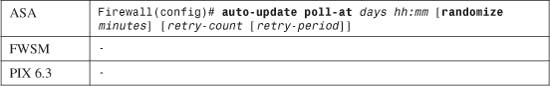
Beginning with ASA 7.2(1), you can configure specific days and times to poll the AUS. Specify the days as a list of one or more day names separated by spaces. You can use any of the following: monday, tuesday, wednesday, thursday, friday, saturday, sunday, daily (every day of the week), weekdays (Monday through Friday), or weekend (Saturday and Sunday). The day names are not case sensitive.
Define the time to poll on each of the days as hh:mm, in 24-hour format. Make sure the firewall clock is configured accurately. For more information, see Section “10-1: Managing the Firewall Clock” in Chapter 10, “Firewall Logging.”
You can also use the randomize keyword to specify the number of minutes past the hh:mm time that the firewall can poll the AUS. The firewall attempts to choose a random value within the time range so that it does not always poll at the same exact time each day. This is useful if you have a large number of firewalls polling a single AUS so that they do not all try to download files simultaneously.
If an AUS connection fails, the firewall can retry the connection retry-count times (the default is 0—no retries). If the retry-count is nonzero, the AUS connections are retried every retry-period minutes (1 to 35,791 minutes; the default is 5 minutes).
6. (Optional) Make Auto Update polling mandatory:
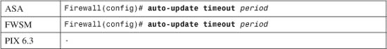
If your security policies dictate that your firewalls must be updated with the most recent code images at all times, you can configure ASA and FWSM platforms to require Auto Update service.
In this case, the firewall must successfully contact the AUS at each scheduled interval. If the AUS is not reachable for a period of time, defined as period seconds (0 to 35,791 seconds), the firewall stops passing any traffic through itself. This can be considered a brute force security method, where the firewall does not operate unless it is sure it has the latest code image.
Caution
Use caution if you decide to enable mandatory Auto Update polling, because an unreachable AUS might cause the firewall to abruptly stop forwarding traffic when you least expect it. By default, the period is set to 0 seconds, disabling the feature.
7. Identify the AUS URL:
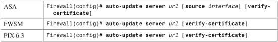
The firewall locates the AUS by its URL, given as the text string url. You can specify the URL in one of the following formats, depending on which AUS platform is being used:
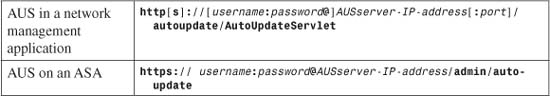
The URL can use http (HTTP, port 80) or https (HTTPS or SSL, port 443) to communicate with the AUS. If you are using an ASA platform as the AUS, you must use the https keyword here.
The firewall can authenticate itself using a valid AUS username and password. If your AUS is embedded in a network management application, then authentication is optional. Usually this type of AUS identifies the firewall by the device ID that is configured in Step 3.
On an ASA AUS platform, however, authentication is required. The username can be any valid username that is accepted by ASDM. If no usernames are configured on the ASA AUS, then the username value should be left blank and password should be the enable password of the ASA.
Tip
AUS uses the same web server and authentication methods that are used by ASDM. If you can successfully authenticate to an ASDM session, you can use the same username and password for AUS. You can use the aaa authentication http console command to enable specific username authentication; if you use the no form of the command, the username must be blank and the enable password used.
The IP address of the AUS is given as AUSserver-IP-address. The port used can be determined by the http or https keyword (80 or 443, respectively) or by an explicit port value. If you choose an arbitrary port number, make sure the AUS is configured to operate over the same port. With an ASA AUS, only the http keyword (TCP port 443) can be used.
The path name shown as /autoupdate/AutoUpdateServlet is the standard value for AUS in a Cisco network management system. If you are using an ASA platform as an AUS, the path must be given as /admin/auto-update.
You can optionally make the firewall verify the SSL certificate from the AUS as an added security feature. This prevents the firewall from downloading files from a rogue AUS machine. The client firewall must have its own certificate issued by the same certificate authority (CA) as the AUS.
Finally, you can repeat the auto-update server url command to define multiple AUS. The client firewall begins with the first AUS configured. If it is unreachable or unresponsive, the client moves on to the next AUS in the list, and so on, in a round robin fashion.
As an example, an ASA is configured as an Auto Update client. The AUS is a network management application located at 10.10.10.1. The client ASA should poll the AUS each Saturday and Sunday at 11:30 p.m., but also at a random time up to 30 minutes later. If the AUS is not responsive, the client should retry three more times at 5-minute intervals.
The following configuration commands could be used to accomplish this:
Firewall(config)# auto-update device-id hostname
Firewall(config)# auto-update poll-at saturday sunday 23:30 randomize 30 3 5
Firewall(config)# auto-update server https://10.10.10.1/autoupdate/AutoUpdateServlet
Suppose the same ASA client is configured to use another ASA as the AUS, located at 10.10.10.10. The ASA AUS is configured to use its default authentication, with no username and the enable password ausenablepass. The following configuration commands could be used instead:
Firewall(config)# auto-update device-id hostname
Firewall(config)# auto-update poll-at saturday sunday 23:30 randomize 30 3 5
Firewall(config)# auto-update server https://:[email protected]/admin/auto-update
Notice that when the username is left blank, the colon must still be given as a separator just before the password. If the ASA AUS is configured to use actual usernames, such as a user named ausclient, the last command would appear as follows:
Firewall(config)# auto-update server
https://ausclient:[email protected]/admin/auto-update
Verifying Auto Update Client Operation
After an Auto Update client has been configured, the polling operation becomes rather silent. You can verify the AUS operation or monitor its progress in several ways.
On the client firewall, you can use the following EXEC command to see the current AUS poll status:
Firewall# show auto-update
For example, the following output from a client firewall shows the server URL (an ASA acting as an AUS, in this case), the polling schedule, and the device ID. The date and time of the next poll cycle is shown, along with the date and time of the last poll. During the last poll, the ASDM image was updated with a new image file from the AUS.
Firewall# show auto-update
Server: https://10.10.10.10/admin/auto-update
Poll weekend randomly between 23:30 and 0:00, retry count: 3, retry period: 5 minutes
Timeout: none
Device ID: host name [Firewall]
Next poll in 2148.23 minutes at 23:37:22 UTC Sat Apr 14 2007
Last poll: 23:32:10 UTC Sat Apr 7 2007
Last ASDM update: 23:32:10 UTC Sat Apr 7 2007
Firewall#
You should also know what to expect when a client firewall successfully polls an AUS and downloads a new file.
As soon as a new configuration file is retrieved from AUS, the firewall executes a clear xlate command automatically. This clears the translation table in preparation for a changed configuration, but might temporarily disrupt active connections through the firewall.
As soon as a new operating system image file is retrieved from the AUS, the client firewall writes the file to its flash memory and then reloads itself immediately and without prior warning. The reload disrupts active connections and traffic passing through the firewall until the updated image is booted and operational.
If an ASDM image is retrieved from the AUS, the new file is written into flash memory and is available for new ASDM sessions. No other firewall operations are disrupted.
Tip
Sometimes you might configure a polling schedule, only to realize that it should be cancelled or changed. To change the polling schedule, locate the poll-period or poll-at command in the running configuration, then reenter the command with the new polling schedule. The new schedule takes effect immediately and can be confirmed by using the show auto-update command.
Configuring a Firewall as an Auto Update Server
You can configure an ASA to act as an AUS, if the ASA is running release 7.2(1) or later. This can be useful if you do not have an enterprise network management platform with an embedded AUS. The ASA AUS can be used to offer operating system and ASDM image files to other ASA and PIX firewall platforms—as long as they are running release 7.2(1) or later already.
The image file can be stored on an external web server or on the ASA AUS itself. The most scalable solution is to store firewall image files on a web server. There you have more space for large image files and CPU resources dedicated to serving up files via HTTPS or SSL. The web server does not have to keep track of which image file should go to which firewall platform—the ASA AUS manages the file associations and simply directs the Auto Update clients toward the correct file on the web server.
If you choose to store image files on the ASA, you are limited by the size of the ASA’s flash memory. In addition, the ASA’s CPU can be impacted when Auto Update clients begin downloading new images from it. This can affect the ASA’s performance as a security appliance, so use caution as you configure new Auto Update client firewalls. At the least, the clients should be configured to poll the ASA AUS during scheduled maintenance windows or during times of low traffic impact.
You can use the following steps to configure an ASA as an AUS:
1. Associate client firewalls with an image file.
For each image file the AUS offers, you need to define the potential client firewalls that can receive the file. For example, maybe you might want all ASA platforms, regardless of model, to receive the same image file. Or an ASA 5510 might receive one file, whereas an ASA 5550 might receive another file. PIX platforms running a PIX version of ASA code could receive still other files.
Choose one of the methods described in 1a, 1b, 1c, or 1d to identify potential clients and their image. In each of the methods, the configuration command ends with the following syntax:
component {image | asdm} url url-string rev-nums rev-nums
The component keyword is used to define the image file as either an operating system image (image) or an ASDM image (asdm).
The file is located by its URL, given as url_string. The URL is returned to the Auto Update client, which in turn attempts to download the file directly.
If the file is actually stored on an external web server, the url_string is simply the URL where the file can be accessed. For example, if the file asa801.bin is stored on the web server at 10.10.10.1 in the /firewall-images directory, the url_string would be:
http://10.10.10.1/firewall-images/asa801.bin
If the file is stored on an ASA AUS, the url_string is slightly different. The ASA AUS always requires HTTPS with client authentication, so a username and password must be given. The url_string format would be:
https://username:password@10.10.10.1/admin/flash/asa801.bin
Finally, the AUS must identify an image release number with the image file. The rev-nums keyword specifies a release or revision number string, rev_nums. Although the rev_nums string is completely arbitrary, you should specify the exact release number of the software image.
For example, ASA release 7.2(1) would be defined as rev-nums 7.2(1), release 8.0(1) would be rev-nums 8.0(1), and release 8.0(3)32 would be rev-nums 8.0(3)32.
Tip
The rev-nums value is returned to an Auto Update client so that the client can decide if the server’s image is newer than the image it is already running. In other words, the client’s version (displayed by the show version command) is compared against the rev-nums rev_nums string from the AUS.
If the server’s image is newer (a greater release number), the client attempts to download the file at the URL it received. If the release number is not greater, the client waits until the next polling cycle and checks again.
When the client polls the AUS, it checks both the operating system image and the ASDM image rev_nums values. The client downloads either file (or both) if it has a higher revision number.
a. Offer a file to a family of client firewalls:
Firewall(config)# client-update family {asa | pix | family_name} component {image
| asdm} url url-string rev-nums rev-nums
With the family keyword, a family of firewalls is defined as a common platform, such as ASA or PIX, which includes all of the specific models. For example, using the asa keyword would associate ASA 5505, ASA 5510, ASA 5520, ASA 5540, and ASA 5550 clients with a single image file.
If, for some reason, you find that your client firewalls do not fit into one of the predefined family names, you can enter an arbitrary text string as the family_name.
b. Offer a file to a specific model of client firewalls:
Firewall(config)# client-update type type component {image | asdm} url url-string
rev-nums rev-nums
With the type keyword, a type of firewall platform is defined as a specific model. You can use one of the following predefined ASA model types: asa5505, asa5510, asa5520, asa5540, or asa5550. For a PIX client, you can use one of the following: pix-515, pix-515e, pix-525, or pix-535.
For models that do not match any of the predefined type keywords, you can enter type as an arbitrary text string.
Tip
Before you choose a type keyword, you should verify that your client firewall actually matches the type that is configured on the AUS. If the client reports a hardware type that is different from that configured on the AUS, the client does not download any files.
For example, some ASA 5510 devices identify themselves as “asa5510”, whereas other ASA 5510 devices report “asa5510-k8” instead. How can you verify the hardware or model type? Look at the output of the show version command on the client firewall. The client reports its hardware type as the string right after “Hardware:”. For example, the following output shows that an ASA 5510 identifies itself as an “ASA5510-K8” hardware type:
Firewall# show versionCisco Adaptive Security Appliance Software Version 8.0(1)Device Manager Version 6.0(1)Compiled on Thu 29-Mar-07 01:37 by buildersSystem image file is "disk0:/image.bin"Config file at boot was "startup-config"Firewall up 6 hours 54 minsHardware: ASA5510-K8, 256 MB RAM, CPU Pentium 4 Celeron 1600 MHzInternal ATA Compact Flash, 256MBBIOS Flash M50FW080 @ 0xffe00000, 1024KB[output truncated]
Therefore, the following command would associate this client with the appropriate image file:
Firewall(config)# client-update type asa5510-k8 component image ...
c. Offer a file to a specific client firewall:
Firewall(config)# client-update device-id dev_string component {image | asdm} url
url_string rev-nums rev_nums
With the device-id keyword, a single, specific client firewall is targeted for the image file. When the client polls the AUS, it presents its own device ID—either its hostname, serial number, IP address, MAC address, or an arbitrary text string. You should define dev_string to match the device ID that the client is configured to send.
d. Offer a file to any client firewall:
Firewall(config)# client-update component {image | asdm} url url_string rev-nums
rev_nums
With the component keyword alone, no other means of identifying client firewalls is used. The AUS matches any polling client to the image file. This method should be used only if all of your client firewalls are of the same platform or family. Otherwise, an ASA might receive a PIX iamge, or vice versa.
2. Enable the AUS feature:
Firewall(config)# client-update enable
After the AUS feature is configured and enabled, it goes about its business rather silently. You can use two debugging methods to monitor the AUS activity:
a. Debug HTTP server activity:
Firewall# debug http
The ASA AUS uses its own HTTP server to communicate with firewall clients. If image files are stored on the ASA’s flash file system, the same HTTP server delivers the image files to the client.
You can enable debug output for the HTTP server with this command. The debug output is sent to your CLI session while the session remains active. The HTTP debug output shows each request from the client, the username sent by the client to authenticate with the AUS, and files sent to the client.
b. Debug the AUS activity:
Firewall# debug auto-update server
You can enable debug output for the AUS with this command. The debug output shows the device attributes and identity sent with each client poll. You can use this information to verify the device ID, family, and hardware type being sent by the client so that your AUS is configured to match. The debug output also shows the image file URL and revision number that are returned to the client after an appropriate image file is found for the client.
In the following example, an ASA 5510 client (10.10.10.99) polls the AUS (10.10.10.10). The client authenticates itself with the username “ausclient”. As soon as it is authenticated with the ASA AUS HTTP server, the client sends its device ID, platform family, and platform type. The ASA AUS uses that information to find an appropriate image file.
First, the client firewall is configured with the following auto-update commands:
Firewall-client(config)# auto-update device-id hostname
Firewall-client(config)# auto-update poll-at weekend 23:30 randomize 30 3
Firewall-client(config)# auto-update server https://*@10.10.10.10/admin/auto-update
The ASA AUS is configured with the following client-update commands:
Firewall-aus(config)# username ausclient password password123
Firewall-aus(config)# aaa authentication http console LOCAL
Firewall-aus(config)# client-update type asa5510-k8 component image url http://
10.10.10.200/asa801-k8.bin rev-nums 8.0(1)
Firewall-aus(config)# client-update type asa5510-k8 component asdm url https://
ausclient:[email protected]/flash/asdm-601.bin rev-nums 6.0(1)
Firewall-aus(config)# client-update enable
Both HTTP and AUS debug output are shown in the following example:
HTTP: processing POST URL '/admin/auto-update' from host 10.10.10.99
HTTP: Authentication username = 'ausclient'
Auto-update server: Processing DeviceDetails from host 10.10.10.99
DeviceID: Firewall
PlatformFamily: ASA
PlatformType: ASA5510-K8
Auto-update server: Sent UpdateInfo to host 10.10.10.99
Component: asdm, URL: https://ausclient:[email protected]/flash/asdm.bin,
Version: 6.0(1)
Component: image, URL: http://10.10.10.200/asa801-k8.bin, Version: 8.0(1)
HTTP: processing GET URL '/flash/asdm-601.bin' from host 10.10.10.10
HTTP: Authentication username = 'ausclient'
HTTP: sending file: flash:/asdm-601.bin, length: 6727152
Notice that the AUS informs the client of two image files: one ASDM image and one operating system image.
The URLs of each are also sent, so the client can locate the files if it decides that it needs to download them. The ASDM image file is located on the AUS’s own flash file system, whereas the operating system image is located on an external web server.
4-5 Managing Administrative Sessions
Administrators and firewall users can open interactive sessions with a firewall using any of the following methods:
• A terminal emulator connected to the console port
• Telnet
• SSH
• Web-based management applications such as ASDM or PDM
The following sections provide information about the configuration and use of these methods.
Console Connection
Most Cisco firewall and security appliances have a physical console connection that can be used to access a user interface. The console port is an asynchronous serial interface operating at 9600 baud. Because of its relatively slow speed, the console should be used only to initially configure the firewall or to access it over an out-of-band connection as a last resort.
Because the FWSM is integrated into a Catalyst 6500 or 7600 switch chassis, it does not have a readily accessible console port. It does have an emulated console connection you can reach from the switch user interface by specifying the FWSM module number in the following command:
Switch# session slot module processor 1
The session slot command is actually a special Telnet session to the FWSM over the Catalyst 6500 backplane. Normally, the emulated console session provides reliable access to the FWSM, even if none of its interfaces are operational.
Tip
The FWSM also has a physical console port, like any other firewall platform. However, the console is not easy to access—it is an RJ-45 jack labeled “P0”, located on the FWSM’s printed circuit board.
If you decide to use this console port, you should connect a cable while the FWSM is pulled out of the switch chassis. Then, slide the FWSM in and carefully thread the cable out through an adjacent slot.
Even if you do not connect to the onboard console port, the FWSM keeps a running 1 KB buffer that captures all of the console’s output. You can view the console buffer with the show console-output EXEC command. You can also clear the console buffer with the clear console-output EXEC command. The console buffer can be useful when you need to see the actual bootup messages from the last FWSM boot sequence.
The console port is always active and cannot be disabled. When a user connects to the console port with a terminal emulator, the firewall immediately begins at the unprivileged or user EXEC level. To use any type of administrative or configuration commands, the console user must move into privileged EXEC or enable mode.
Best practice dictates having the firewall close any user session that has been idle for a period of time. By default, console connections never idle out. You can change this behavior with the following configuration command:
Firewall(config)# console timeout minutes
Here, minutes is the idle time value from 0 (no idle timeout; the default) to 60 minutes.
Tip
Even though the FWSM does not have an easily accessible console port, the console timeout command can still be used to close an idle console session. Evidently, this command is meant for environments where the embedded console port is permanently connected to a PC or an out-of-band terminal server.
You can also configure various methods to authenticate users who connect to the console port. Chapter 5, “Managing Firewall Users,” covers these methods in greater detail.
Telnet Sessions
Remote administrators can connect to the firewall using Telnet. Telnet sessions use TCP port 23 and provide the standard firewall command-line interface. Accessing the firewall through Telnet has the following characteristics:
• Up to five different Telnet sessions can be open to the firewall concurrently.
• Telnet access is much more efficient than the firewall’s console port. Large amounts of output can be displayed without imposing a heavy load on the firewall CPU.
• Information sent over a Telnet connection is not secure. No data encryption or authentication is used. (SSH is a more secure alternative.)
• Telnet access is permitted on “internal” firewall interfaces if the firewall is configured to do so. The firewall does not permit inbound Telnet connections on its outside interface unless IPSec is configured on that interface for a secure VPN connection.
To configure Telnet operation, use the following configuration steps:
1. Allow incoming Telnet connections on an interface:
![]()
By default, no Telnet connections are permitted. This command permits inbound Telnet connections from the source addresses defined by ip_address and netmask. The inbound firewall interface is specified as if_name (inside or dmz, for example). You can repeat this command to define multiple Telnet sources.
PIX 6.3 allows these parameters to be optional. If no interface name is given, the firewall allows Telnet connections from the source address on all its interfaces except the outside. ASA and FWSM platforms, however, are more specific and require all the options to be given with the command.
For example, the following command permits inbound Telnet from a host at 192.168.4.13 and the subnet 192.168.177.0/24 on the inside interface:
Firewall(config)# telnet 192.168.4.13 255.255.255.255 inside
Firewall(config)# telnet 192.168.177.0 255.255.255.0 inside
2. (Optional) Set the Telnet idle timeout:
Firewall(config)# telnet timeout minutes
By default, Telnet sessions are automatically closed if they have been idle for 5 minutes. You can change the idle timeout period to minutes (ASA and FWSM: 1 to 1440 minutes, or 24 hours; PIX 6.3: 1 to 60 minutes).
SSH Sessions
Remote administrators can also connect to the firewall using SSH. SSH sessions use TCP port 22 and provide the standard firewall CLI. Accessing the firewall through SSH has the following characteristics:
• Up to five different SSH sessions can be open to the firewall concurrently.
• An SSH session offers a Telnet look and feel while offering a high level of security.
• SSH can be permitted on any firewall interface, including the outside.
• A firewall can support two versions of SSH: SSHv1 (beginning with PIX 6.3, ASA 7.0[1], and FWSM) and SSHv2 (beginning with ASA 7.0[1] and FWSM 3.1[1]).
• SSHv2 offers data integrity and encryption that is superior to SSHv1.
Tip
SSH sessions always require a username and password for authentication. If no specific authentication method is configured other than a basic password, or if the configured AAA authentication servers are unreachable, you can use username pix and the normal EXEC-level password set with the passwd command.
Although you might not expect it, the pix username works on a PIX, ASA, or FWSM platform.
To configure SSH operation, use the following configuration steps:
1. Generate an RSA key pair.
An RSA key pair is needed as a part of the SSH security mechanisms. By default, no RSA keys exist in a firewall, so they must be created and saved.
a. Define a domain name for the firewall:

The domain name is given as name (a text string up to 63 characters). This is usually the domain name of the organization or enterprise where the firewall is located, although you can use any arbitrary name. Because the domain name is included in the RSA key pair computation, you should try to use a name that will be stable over time. Otherwise, the RSA keys must be rebuilt with any new domain name configured later.
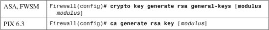
A general-purpose RSA key pair is computed with a modulus or length of modulus bits (512, 768, 1024, or 2048; the default is 768). Generally, a greater modulus provides more security because it makes reversing the key operations more difficult. Longer keys also take longer to generate, requiring more firewall CPU resources. This is not a critical issue, however, because RSA keys are generated only once or only after long periods of time.
As a compromise, the current industry best practice recommends a modulus of 1024 bits.
If you do not define a domain name before using this command, a default domain name (ciscofwsm.com on an FWSM or ciscopix.com on a PIX or ASA) is used.
c. Save the RSA key information:

The contents of the RSA key pair are not saved as a part of the firewall configuration. Instead, they must be saved into a private flash memory area. In an ASA or FWSM 3.1+, the RSA keys are automatically saved each time they are generated.
Tip
You can display the public portion of an RSA key pair with the following commands:

If the firewall’s domain name ever changes, the RSA key pair must be cleared and rebuilt. You can use the following commands to clear the stored key pair:

Repeat Steps 1a through 1c to regenerate a new key pair based on the new domain name.
2. Allow incoming SSH connections on an interface:
![]()
By default, no SSH connections are permitted. This command permits inbound SSH connections from the source address given by ip_address and netmask on the firewall interface named if_name (inside or outside, for example).
In PIX 6.3, if the netmask is omitted, a host mask of 255.255.255.255 is assumed. If the if_name is omitted, the firewall automatically duplicates this command for each of its active interfaces.
You can repeat this command to define multiple SSH sources and source interfaces.
3. (Optional) Specify the supported SSH versions:
![]()
In releases before ASA 7.0(1) and FWSM 3.1(1), SSHv1 is the only version that is supported. Beginning with ASA 7.0(1) and FWSM 3.1(1), both versions 1 and 2 are supported by default.
This command can be used to restrict SSH support to only a single version, either version 1 or 2. To return to the default where both versions are allowed, use the no ssh version command with no other arguments.
You can see what SSH versions are currently allowed by using the show ssh command. In the following example, SSH support starts with only version 1. The firewall is configured back to the default for versions 1 and 2. Then only version 2 is configured.
Firewall# show ssh
Timeout: 30 minutes
Versions allowed: 1
172.21.4.0 255.255.255.0 outside
172.21.6.0 255.255.255.0 outside
Firewall# configure terminal
Firewall(config)# no ssh version
Firewall(config)#
Firewall# show ssh
Timeout: 30 minutes
Versions allowed: 1 and 2
172.21.4.0 255.255.255.0 outside
172.21.6.0 255.255.255.0 outside
Firewall# configure terminal
Firewall(config)# ssh version 2
Firewall(config)#
Firewall# show ssh
Timeout: 30 minutes
Version allowed: 2
172.21.4.0 255.255.255.0 outside
172.21.6.0 255.255.255.0 outside
Firewall#
4. (Optional) Set the SSH idle timeout:
Firewall(config)# ssh timeout minutes
SSH sessions idle out after 5 minutes by default. You can change the idle timeout to minutes (1 to 60).
ASDM/PDM Sessions
You can also manage, configure, and monitor a firewall through a web-based application. ASDM and PDM are two of the supported applications. Each one runs from an image stored on the firewall itself, which was made available through an embedded web server.
The web-based management application is named differently for the various firewall platforms:
• PDM 3 (PIX 500 series running PIX 6.3)
• PDM 4 (FWSM)
• ASDM 5.0 (ASA and PIX running 7.0), ASDM 6.0 (ASA and PIX running 8.0).
You can use the following steps to configure and prepare a firewall for PDM or ASDM use:
1. Identify the PDM/ASDM image to use:
![]()
In releases before ASA 7.0(1), the ASDM image is always stored in a fixed location in flash memory. For example, PIX 6.3 uses flash file 3. Beginning with ASA 7.0 (1), you can specify the flash device (flash:/, disk0:/, or disk1:/) and path to the ASDM image file. If the firewall is in multiple-context security mode, you can use this command only from the system execution space.
In the following example, the ASDM image file is stored as flash:/asdm.bin (flash:/ is also disk0:/ on this platform):
Firewall# dir flash:/
Directory of disk0:/
10 -rw- 8688476 06:25:20 Dec 21 2006 asdm.bin
11 -rw- 5031936 06:12:14 Dec 21 2006 image.bin
62881792 bytes total (44142592 bytes free)
Firewall# configure terminal
Firewall(config)# asdm image disk0:/asdm.bin
2. Install the ASDM/PDM image file.
You can copy an ASDM or PDM image file into a firewall’s flash memory with the following commands:
![]()
Before ASA 7.0, the PDM image file was automatically stored in the correct location. Therefore, only the flash:pdm destination was needed.
Beginning with ASA 7.0(1), the ASDM image file can be stored anywhere in flash memory and can have an arbitrary filename. You can have one or more ASDM image files stored in flash at any time, provided that you have sufficient storage space, but only one of them can be used to run the application.
The source url can be one of the following:
ftp://[user[:password]@]server[:port]/[path/]filename[;type=xy]
tftp://[user[:password]@]server[:port]/[path/]filename
http[s]://[user[:password]@]server[:port]/[path/]filename
If the server requires user authentication, you can specify the user ID and password in the user:password@ format. Section “4-2: Managing the Flash File System,” provides more details about copying files into flash memory.
On an ASA, the destination must be a local flash device, such as flash:/, disk0:/, or disk1:/, in a specific path name, given by /path. On FWSM or PIX platforms, the ASDM image file is always written to a fixed location; it overwrites an existing file if one is present.
3. Permit incoming access.
ASDM and PDM are web-based applications. Therefore, clients must connect to an HTTP server that is embedded in the firewall.
a. Identify client locations:

Only source or client addresses that fall within the address range given by ip_address and subnet_mask and are located on the firewall interface named if_name (outside, for example) are allowed to connect to the firewall’s HTTP server.
On ASA and FWSM platforms, all the arguments are required and must be given in the command. Prior releases allow optional arguments. For example, if the subnet mask is omitted, a host mask of 255.255.255.255 is assumed. If the interface name if_name (outside, for example) is omitted, the inside interface is assumed.
Note
After you have configured access to the HTTP server, you do not also have to add anything to any of the firewall’s access lists. Inbound HTTP access to the firewall itself is permitted on the configured interface(s) automatically.
b. Enable the embedded HTTP server:
Firewall# http server enable
Starting the ASDM or PDM Application from a Web Browser
To run ASDM or PDM from a web browser, point your web browser to the following URL:
https://ip_address[/admin]
The ip_address is the address (or host name) of the firewall interface that is configured to allow HTTP server connections.
The /admin portion of the URL is applicable only to ASA platforms. If the SSL VPN feature is also enabled, the security appliance’s default web page (https://ip_address) is devoted to SSL VPN services rather than ASDM. In this case, you can differentiate between the services by using a more specific URL:
• ASDM—https://ip_address/admin
• SSL VPN—https://ip_address/access
Note
Your browser must allow popups from the firewall’s address, because ASDM/PDM is automatically started in a new browser window. As well, ASDM/PDM runs as a Java applet that is downloaded from the firewall. Your browser must support Java so that the applet can be run.
As ASDM or PDM begins, you need to authenticate as an administrative user. The firewall can have an authentication method that is specific to HTTP connections, configured with the aaa authentication http console command. Depending on the configuration, you need to use one of the following credentials:
• Default authentication—No usernames are defined or used. Therefore, leave the username field blank and enter the enable password.
• Local authentication—Usernames are used and are defined locally on the firewall with the username command. Enter a valid username that can use privilege level 15 (enable or privileged EXEC mode) and the appropriate password.
• AAA authentication—Usernames are used and are defined on external AAA servers. Enter a valid username that can use privilege level 15 (enable or privileged EXEC mode) and the appropriate password.
Tip
When the ASDM or PDM application connection is initiated, the firewall sends its self-signed SSL certificate to your web browser. Sometimes a browser cannot verify the certificate because the firewall is not known as a trusted certificate authority. If this happens, you likely will see a message from the web browser.
You can choose to accept the certificate temporarily or permanently if you are comfortable that you are connecting to the correct firewall. You can check the firewall’s identity by viewing the certificate; the Common Name (CN) attribute is made up of the firewall’s host name and domain name.
You might also see an error regarding a domain name mismatch. If the firewall’s interface IP address is not registered in a DNS, the browser cannot confirm that its IP address and certificate CN (fully qualified domain name) correlate. If you are comfortable with the mismatch, you can choose to continue.
Starting ASDM from a Local Application
Beginning with ASA 7.0(1), you can run ASDM from a web browser or from a “launcher” application that has been downloaded directly to your PC. The first time you use ASDM, you should point your web browser to the following URL:
https://ip-address/admin
This brings up a web page where you can choose the ASDM access method. Figure 4-8 shows an example of this opening page.
Figure 4-8 Initial ASDM Launch Page
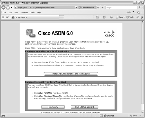
Running ASDM as a local application is usually better because you can use one common program on your PC to access one or more ASA devices. The application also maintains a drop-down list of firewall addresses where you have connected in the past, making it easy to select a target firewall without having to use browser bookmarks or enter URLs.
When the local application is installed, an installer file is downloaded, as shown in Figure 4-9. The installer runs automatically.
Figure 4-9 Local ASDM Application Installation
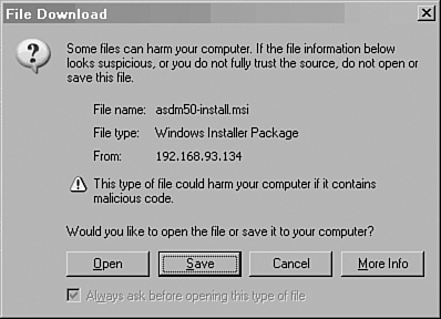
To run the ASDM launcher application, start the local Cisco ASDM Launcher program. On a Windows PC, it can be found on the Start menu under Programs > Cisco ASDM Launcher. When the launcher starts, it displays a drop-down list of firewall addresses it knows about. Select an address from the list and enter your authentication credentials. Figure 4-10 shows an example of the launcher application.
Figure 4-10 Local ASDM Launcher Application
After you have authenticated, the firewall downloads the most current ASDM application code to your PC via the launcher application. This means the local application rarely needs to be updated. Instead, the PC is always kept current with the actual ASDM software that is contained in the firewall’s ASDM image. As soon as ASDM launches, it looks like the window shown in Figure 4-11.
Figure 4-11 Sample ASDM Session
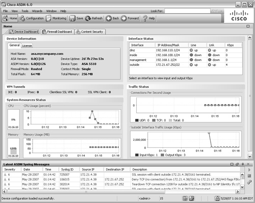
User Session Banners
You can configure a banner of text that the firewall will display to any administrative users. You can use the following three types of banners:
• Message of the Day (MOTD)—An informational message that is shown before the login prompt in a Telnet, SSH, or console session. This might include network news, access policy information, or legal warnings to be presented to potential users.
• Login—A message that is shown after the MOTD prompt and just before the firewall login prompt. This might be useful to show a name, location, or other access parameters.
• Exec—A message that is shown just after a user successfully logs in and reaches EXEC mode. This might be useful if you need to present some final words of caution or a warning to the user who has just logged in and is about to view or change something on the firewall.
To configure one of these banners, use the following configuration command:
Firewall(config)# banner {exec | login | motd} text
Here, the banner is created one line of text at a time. Do not enclose the text in quotation marks; the text begins after the banner type keyword and ends at the end of the line. Repeat this command for subsequent lines of the banner.
You cannot edit a banner; you have to delete the entire banner with the no banner {exec | login | motd} command and re-enter it. To delete banners of all types, you can use the clear banner (PIX 6.x and FWSM 2.x) or clear configure banner (ASA and FWSM 3.x) command.
You can also customize the banner’s appearance by including the firewall’s host name or domain name. This is done automatically by inserting the token strings $(hostname) and $(domain) within the banner text. The firewall substitutes the current values configured by the hostname and domain-name commands.
Tip
If you decide to use banners on your firewall, be careful what information you include. Remember that the MOTD and login banners are displayed as soon as a Telnet or SSH session connection is opened to the firewall—whether someone can log in or not. That means if someone can initiate a Telnet session and see the login prompt, he can also see any detailed banner information that might reveal the firewall’s location, model, software version, and so on.
Also be careful when you craft a banner message. Most security and legal experts advise against using any type of “Welcome” or “Greetings” message, because this might be used against you. Malicious users might try to suggest that you welcomed them into your firewall! For some best-practice recommendations, refer to http://www.cisco.com/warp/public/707/21.html#warnin.
Monitoring Administrative Sessions
Having a console interface and network access, a firewall can allow several people to be connected at any time.
You can monitor all the active Telnet sessions on a firewall with the EXEC command who, which provides a list of Telnet session numbers along with the originating IP address, as in the following example:
Firewall# who
1: 172.21.4.16
Firewall#
If you need to close a Telnet session that is either hung or unwanted, use the who command to find the session’s index number. Then use the kill telnet_id privileged EXEC command, where telnet_id is the session index, to terminate that session immediately and without warning. For example, the following commands could be used to end the Telnet session coming from IP address 10.6.6.6:
Firewall# who
0: From 10.10.10.71
1: From 192.168.199.4
2: From 10.6.6.6
Firewall# kill 2
You can also monitor active SSH sessions with this EXEC command:
Firewall# show ssh sessions
For example, a generic user (“pix”) has several SSH sessions open. Notice that SSH version 1 is actually shown as version 1.5. Version 1.5 is commonly used with Cisco IOS Software and has several security fixes beyond that of version 1.0.
Firewall# show ssh sessions
SID Client IP Version Mode Encryption Hmac State Username
0 172.21.4.14 1.5 - 3DES - SessionStarted pix
1 172.21.4.14 2.0 IN aes256-cbc sha1 SessionStarted pix
OUT aes256-cbc sha1 SessionStarted pix
2 172.21.4.14 1.5 - 3DES - SessionStarted pix
3 172.21.4.14 1.5 - 3DES - SessionStarted pix
4 172.21.4.14 1.5 - 3DES - SessionStarted pix
You can disconnect an active or hung SSH session with the following command:
Firewall# ssh disconnect session-id
To display the active ASDM or PDM management application sessions, you can use the following command:
![]()
You can disconnect an active PDM session with the following command:
![]()
Tip
A firewall can also generate an audit trail that shows user activity. To do this, logging must be enabled on the firewall. See Chapter 10 for logging configuration details.
• User authentication messages are generated at Syslog severity 6 (Informational). This also includes SSH and ASDM/PDM sessions.
• User privilege level event messages are generated at Syslog severity 5 (Notification).
• Firewall commands executed by users are logged at Syslog severity 5 (Notification), and show commands executed are logged at Syslog severity 7 (Debugging).
4-6 Firewall Reloads and Crashes
During a firewall’s normal operation, you might find an occasion to manually reboot or reload it. As well, the firewall might crash on its own, because of some unexpected software or hardware problem, and possibly reload itself. The following sections discuss the methods you can use to make a firewall reload and diagnose the cause of a crash.
Reloading a Firewall
To manually trigger a firewall reload, choose one of the options discussed in the following sections. You can initiate a firewall reload only from privileged EXEC (enable) mode. On an ASA or FWSM firewall platform running in multiple-context security mode, you can initiate a reload only from the system execution space.
Reloading a Firewall Immediately
You can use the following command to initiate an immediate reload. Be aware that as soon as the reload begins, all existing connections through the firewall are dropped, and traffic cannot pass through for a minute or more. Reloads should be initiated only during a network maintenance window.
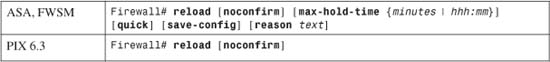
With PIX 6.3, a manual reload occurs immediately. The firewall prompts you for a confirmation of the reload and to save the running configuration if it differs from the startup configuration. To answer the confirmations, you can enter y or just press the Enter key. You can avoid all the confirmation prompts by using the noconfirm keyword.
ASA and FWSM platforms add more flexibility to the reload process. By default, the firewall informs all the administrative users with active sessions (console, Telnet, and SSH) of the impending reload. It also attempts to shut down each of its software modules (IPSec VPN remote access, for example) before the reload. This allows every reload to happen gracefully, without catching users and functions off-guard.
You can use one or more of these keywords with the reload command to change the reload behavior:
• max-hold-time—You can limit how long the firewall waits to inform users and shut down security functions. Specify the number of minutes to wait (1 to 33960) or as hours and minutes hhh:mm (up to 566 hours 0 minutes). After that maximum hold time expires, the firewall is free to abruptly perform the reload.
• quick—Perform an abrupt reload without informing users or shutting down processes.
• save-config—Force the firewall to save the running configuration to the nonvolatile startup configuration—even if it has already been previously saved.
• reason—Provides a descriptive reason for the reload as text (an arbitrary string of up to 255 characters). The reason text is displayed to any active administrative users connected with console, Telnet, or SSH sessions.
Reloading a Firewall at a Specific Time and Date
Beginning with ASA 7.0(1) and FWSM 3.1(1), you can schedule a firewall reload at some specific time in the future. This might be handy if reloads are permitted only during a predetermined maintenance window. The command for reloading a firewall at a specific time and date is as follows:
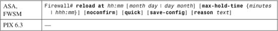
A firewall can schedule a reload at a specific hour and minute, given as hh:mm. You can also specify a month and day (1 to 31). The month can be abbreviated as long as it denotes a unique month name. If no date is given, the reload time is assumed to be within the next 24 hours. Also, the date and time must be within 576 hours 0 minutes (or 24 days) from the time the command is issued.
The remaining reload keywords are optional and are discussed in the preceding section.
Before using this command, be certain that the firewall clock is set and is accurate. You should also confirm that the reload time is based on the same time zone information that the firewall is using. Otherwise, your concept of the reload schedule might be quite different from the firewall’s concept! You can view the current firewall date and time with the show clock command.
If needed, you can set the date and time with the following command:
Firewall# clock set hh:mm:ss {month day | day month} year
Refer to Section “10-1: Managing the Firewall Clock,” in Chapter 10 for complete information about setting and maintaining the clock.
Reloading a Firewall After a Time Interval
You can schedule a firewall reload after a specified amount of time has elapsed. This might be useful if the reload should be delayed from the present time, to allow users a “grace period” to complete their work. The command for reloading a firewall after a time interval is as follows:
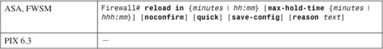
You can schedule a reload at some specific delay after the current time. The delay is given as minutes (1 to 34560) or as hours and minutes as hhh:mm. In either case, the delay limit is 576 hours 0 minutes from the current time.
The remaining reload keywords are optional and are discussed in the section “Reloading a Firewall Immediately” earlier in the chapter.
Tip
On ASA and FWSM platforms, you can display a scheduled reload that is pending with the show reload command. If you need to cancel the reload ahead of time, use the reload cancel command. Obviously, as soon as the actual reload has begun, there is no way to cancel it.
The following example shows how a reload is scheduled at a certain date and time and how that reload is later canceled.
Firewall# show clock
16:10:01.743 EST Sun May 6 2007
Firewall# reload at 23:50 may 9 save-config reason Firewall is being
reloaded for an OS Image upgrade
Cryptochecksum: f96855f6 676cf300 d7f31ae8 bd4cbdcf
3250 bytes copied in 0.530 secs
Proceed with reload? [confirm]
Firewall#
***
*** --- SHUTDOWN in 79:38:41 ---
***
*** Message to all terminals:
***
*** Firewall is being reloaded for an OS Image upgrade
Firewall#
Firewall# show reload
Reload scheduled for 23:50:00 EST Wed May 9 2007 (in 79 hours and 38
minutes) by enable_15 from ssh (remote 172.21.6.1)
Reload reason: Firewall is being reloaded for an OS Image upgrade
Firewall#
Firewall# reload cancel
Firewall#
***
*** --- SHUTDOWN ABORTED ---
Firewall#
Firewall# show reload
No reload is scheduled.
Firewall#
When a reload has been successfully scheduled, the firewall also generates Syslog message ID 199007. If a reload is canceled, a Syslog message 199008 is generated. Both messages are default severity level 5.
Obtaining Crash Information
If a firewall crashes for some reason, you might be left with few clues other than it reloaded or was left at the monitor prompt. You can configure the firewall to save a crashinfo image of its RAM memory as a file in flash memory. The image also includes the output of many commands that show the status of the firewall and its resources. A firewall stores only one crashinfo file; subsequent crashes overwrite it. Therefore, only information from the most recent crash is available.
After a crash, you can examine the crashinfo file to determine the cause of the crash—even after a power cycle or reload. This information is useful to the engineers at the Cisco Technical Assistance Center (TAC) as they track down the source of a firewall problem.
The following sections discuss preparing for and examining a crashinfo image.
Controlling Crashinfo Creation
You can use the following configuration command to automatically save a crashinfo file during a firewall crash:

By default, crashinfo collection is enabled on all firewall and security appliance platforms. If you decide to disable crashinfo collection, you can use the following command:

In ASA, PIX, and FWSM releases, you can see the current status of crashinfo creation by using the show crashinfo save command.
When a PIX 6.3 platform crashes, an image of the firewall RAM is saved in flash memory as file number 4. The size of the image equals the amount of RAM in the firewall.
On ASA and FWSM platforms, the crashinfo file is created and saved in a hidden flash file system. The actual file cannot be seen in a directory listing, nor can its location be specified or changed.
Generating a Test Crashinfo Image
To create a test version of a crashinfo file and store it in flash memory, enter the following command:
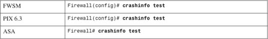
The firewall operation is not hindered or interrupted by entering this command. This command can be used if you just want to get a feel for the crashinfo process and the crashinfo file contents. (Notice that this is a configuration command for PIX 6.3 and FWSM, and a privileged EXEC command for ASA.)
Forcing an Actual Firewall Crash
You can make the firewall produce an error that actually causes itself to crash and to save a legitimate crashinfo image file by entering the following command:

Either a page fault or a watchdog fatal error can be used to cause the crash. A page-fault crash occurs when a firewall process tries to access memory that is outside its own use. A watchdog crash occurs because a firewall process has become unresponsive or hung. In practice, the type of crash does not really matter. The goal is to confirm the process of saving a crashinfo file when the firewall actually crashes.
Notice that this is a configuration command for PIX 6.3, and is a privileged EXEC command for ASA and FWSM.
Caution
The crashinfo force command is useful only for testing the crashinfo procedure. Because it actually crashes the firewall when it is used, you should use this command only under controlled circumstances. As soon as the firewall crashes, no traffic is inspected or passes through it.
In the following example, a watchdog timeout error is used to trigger an actual firewall crash:
Firewall# config terminal
Firewall# crashinfo force watchdog
WARNING: This command will force the PIX to crash and reboot. Do you wish to
proceed? [confirm]:
Watchdog timeout failure! Please contact customer support.
PC SP STATE Runtime SBASE Stack Process
Hrd 001eaa09 0090edc4 00555848 0 0090de3c 3628/4096 arp_timer
Lsi 001effad 009d1fec 00555860 0 009d1074 3928/4096 FragDBGC
Lwe 00119abf 00a5555c 00558fc0 0 00a546f4 3688/4096 dbgtrace
Lwe 003e3f55 00a576ec 0054e188 0 00a557a4 7788/8192 Logger
Hwe 003e80d0 00a5a7e4 0054e438 0 00a5886c 8024/8192 tcp_fast
Hwe 003e8049 00a5c894 0054e438 0 00a5a91c 8024/8192 tcp_slow
Lsi 003006f9 0293c984 00555860 0 0293b9fc 3944/4096 xlate clean
Lsi 00300607 0293da24 00555860 0 0293caac 3888/4096 uxlate clean
[output omitted]
Rebooting....
Viewing the Crashinfo Information
After the crashinfo file is written, it cannot be uploaded from the firewall. Instead, you can view its contents when you enter the following command:
![]()
The show crashinfo command displays all the relevant process and stack trace information that was active during the crash. You should capture all this text output with a terminal emulator so that it can be saved to a file and sent to Cisco TAC.
The first line of output also tells what triggered the crashinfo image. If the line is “:Saved Test Crash,” the image was saved by the crashinfo test command. Otherwise, “:Saved Crash” indicates that the file is the result of an actual firewall crash, as in the following example:
Firewall# show crashinfo
: Saved_Crash
Thread Name: ci/console (Old pc 0x0011f217 ebp 0x02fb2d50)
Traceback:
0: 00104bf8
1: 00102155
2: 0010014a
3: 00338b55
4: 00338c1b
[output omitted]
Deleting the Previous Crashinfo File Contents
Each time a crashinfo file is created, its contents replace the previous file contents. Therefore, only one crashinfo file is stored at any given time, and flash memory is not used up after multiple crashes.
You can, however, clear the contents of the current crashinfo file with the following command:
![]()
This might be useful if your firewall has experienced a crash in the past and you have already resolved the cause of that crash. In that case, you might want an empty crashinfo file to signify that no further crashes have occurred.
4-7 Monitoring a Firewall with SNMP
Simple Network Management Protocol (SNMP) is a protocol that allows the exchange of information about managing a network device. Cisco firewalls can participate in SNMP as follows:
• A Management Information Base (MIB) is a collection of variables stored on a network device. The device can update the variables, or they can be queried from an external source.
• MIBs are structured according to the SNMP MIB module language, which is based on the Abstract Syntax Notation 1 (ASN.1) language.
• An SNMP agent runs on a firewall and maintains various MIB variables. Any query of the variables must be handled through the agent.
• The SNMP agent can also send unsolicited messages, or traps, to an SNMP manager. Traps are used to alert the manager of changing conditions on the firewall.
• An SNMP manager is usually a network management system that queries MIB variables, can set MIB variables, and receives traps from a collection of network devices.
• Cisco firewalls can use SNMP version 1 (SNMPv1), the original version. SNMPv1, based on RFC 1157, has only basic cleartext community strings for security. Access is limited to read-only requests from the IP addresses of one or more SNMP managers.
• Beginning with ASA 7.0(1) or FWSM 1.1(1), firewalls can also support SNMP version 2c (SNMPv2c), an enhanced version based on RFCs 1901, 1905, and 1906. SNMPv2c improves on bulk information retrieval and error reporting but still uses only basic cleartext community strings and IP addresses to provide security. (SNMP security is available only in SNMPv3, which currently is not supported on any Cisco firewall platform.)
Tip
SNMP requests and responses are sent using UDP port 161. Notifications or traps are sent using UDP port 162. The SNMP management station can be located on any interface of a firewall, provided that the firewall has sufficient routing information to reach it.
Overview of Firewall SNMP Support
Firewalls can participate in SNMP by maintaining several MIBs. The MIB values are constantly updated with the current values that are in use. For example, one MIB parameter records the average firewall CPU load over a 5-second period. This is based on the CPU usage measurements that can also be shown from the firewall CLI.
SNMP MIBs represent data as a hierarchical tree structure; each MIB variable is referenced by its object identifier (OID). OIDs are formed by concatenating the name or number of a tree branch as the tree is followed from the root to the object’s location in dotted notation.
Figure 4-12 shows the top layers of the standard MIB tree, along with the lower layers that apply to firewalls. The root layer is unnamed. All MIB variables that are useful for network management are located under the internet subtree. Following the tree structure downward, internet is referenced as OID iso.org.dod.internet or 1.3.6.1.
Figure 4-12 SNMP MIB Structure
Tip
Your SNMP management station needs to have several firewall-specific MIBs compiled into its database. Make sure you find these MIBS: IF-MIB, RFC1213-MIB, CISCO-MEMORY-POOL-MIB, CISCO-PROCESS-MIB, ENTITY-MIB, CISCO-SMI, and CISCO-FIREWALL-MIB.
ASA also adds CISCO-IPSEC-FLOW-MONITOR-MIB, CISCO-FIPS-STAT-MIB, and ALTIGA-SSL-STATS-MIB.
These can all be obtained for free from Cisco.com at http://www.cisco.com/public/sw-center/netmgmt/cmtk/mibs.shtml.
Firewall MIBs
A firewall uses the mgmt subtree (iso.org.dod.internet.mgmt or 1.3.6.1.2) to contain several useful objects, all organized under the mib-2 subtree (1.3.6.1.2.1). These objects are defined in the RFC1213-MIB file (1.3.6.1.2.1.11). They fall into these categories:
• system—Descriptions of the firewall, uptime, and network services
• interfaces—Parameters and counters for each interface
• ip—IP addresses, subnet masks, and broadcast addresses assigned to each interface
Many of the values maintained in the mib-2 subtree can also be seen with the show snmp-server (PIX 6.x), show running-config snmp-server (ASA), show version, and show interface EXEC commands.
The EntityMIB subtree (1.3.6.1.2.1.47) is also included. It is defined by the ENTITY-MIB file, which is based on RFC 1212. This was added to ASA 7.0(1) to support the firewall chassis and field-replaceable units (FRU) available on the ASA platforms.
The private (1.3.6.1.4) subtree contains one subtree, enterprise (1.3.6.1.4.1), where all network vendor-specific objects are located. The Cisco private MIB structure is contained in the cisco subtree (1.3.6.1.4.1.9). The set of specific MIBs that are included under the cisco MIB tree varies according to the hardware platform (router, switch, firewall, and so on).
A firewall maintains several subtrees under iso.org.dod.internet.private.enterprise.cisco.mgmt, as follows:
• The ciscoMemoryPool subtree (1.3.6.1.4.1.9.9.48) has objects that are defined in the CISCO-MEMORY-POOL-MIB file. These describe the current status of firewall memory. It can also be seen with the show blocks EXEC command.
• The ciscoProcess subtree (1.3.6.1.4.1.9.9.109) is defined by the CISCO-PROCESS-MIB file. These values describe the firewall’s CPU usage over 5-second, 1-minute, and 5-minute periods. The same values can be seen with the show cpu usage EXEC command.
• The ciscoFirewall subtree (1.3.6.1.4.1.9.9.147) is defined by the CISCO-FIREWALL-MIB file. A number of values are maintained that describe the current memory buffer usage (cfwBufferStat) and the connection usage (cfwConnectionStat) in the firewall. These correspond to the output of the show memory and show conn count EXEC commands, respectively.
• The ciscoIpSecFlowMonitorMIB subtree (1.3.6.1.4.1.9.9.171) is defined by the CISCO-IPSEC-FLOW-MONITOR-MIB file. This was added to ASA and FWSM platforms to support IPSec VPN functionality to report on tunnel statistics.
• The ciscoRemoteAccessMonitorMIB subtree (1.3.6.1.4.1.9.9.392) is defined by the CISCO-REMOTE-ACCESS-MONITOR-MIB file. This was added to ASA 7.0(1) to support VPN client session statistics, but removed in ASA 8.0.
• The ciscoFipsStatsMIB subtree (1.3.6.1.4.1.9.9.999999) is defined by the CISCO-FIPS-STAT-MIB file. This was added to ASA 7.0(1) to support reporting on IPSec cryptographic engine operations, but removed in ASA 8.0.
• The altigaSSLstats subtree (1.3.6.1.4.1.3076.2.1.2.26) is defined by the ALTIGA-SSL-STATS-MIB file. This was added to ASA 7.0(1) to support reporting on SSL VPN session statistics.
Firewall SNMP Traps
A firewall can send notification or trap messages to SNMP management stations when certain events occur. This allows the management station to receive alerts in real time and relay them to the appropriate networking personnel.
Generic traps are sent when firewall links (interfaces) go up or down, when the firewall is reloaded (a “warm start”) or booted up (a “cold start” after power is applied) for some reason, and when an SNMP poll has been received with an incorrect community string. Syslog messages can also be sent as SNMP traps if the firewall is configured to do so.
When SNMP traps are sent, the firewall’s OID is included. This allows the SNMP management station to determine what type of device has sent the trap. Cisco firewall models use the unique OIDs shown in Table 4-9. Notice that the OIDs use most of the same tree hierarchy as SNMP MIBs. For example, 1.3.6.1.4.1.9. would lead to the private.enterprise.cisco. subtree. This is followed by .1., which points to the Cisco products subtree, which is followed by a number that uniquely identifies the firewall model.
Table 4-9 Firewall OID Values Used in SNMP Traps
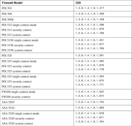
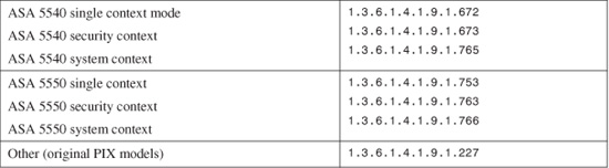
The only exception is when Syslog messages are sent as SNMP traps with the logging history command. The OID used is always 1.3.6.1.4.1.9.9.41.2, regardless of the sending firewall platform.
Tip
You can find the entire list of Cisco product OIDs in the CISCO-PRODUCT-MIB file at ftp://ftp.cisco.com/pub/mibs/oid/CISCO-PRODUCTS-MIB.oid.
SNMP Configuration
You can use the following steps to configure SNMP operation so that a firewall or security appliance platform can be remotely monitored:
a. Identify the firewall location:

Someone at a management station can learn of the firewall’s location by querying the location. This is given by string (a text string of up to 127 characters, including spaces).
b. Identify the firewall administrator:

Querying this string tells someone who to contact in case of firewall problems or issues. The contact information is given by string (a text string of up to 127 characters).
2. Allow SNMP access.
a. Permit access for a specific management station:
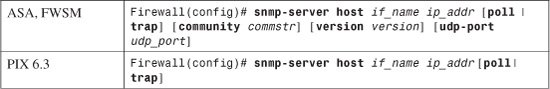
The management station can be found on the firewall interface named if_name (inside or outside, for example) at IP address ip_addr. This command can be repeated to define up to five different stations for PIX 6.3 or up to 32 stations for ASA and FWSM.
The type of access opened to the management station is given by the poll or trap keywords. With poll, the station is allowed to poll the firewall with SNMP queries. The trap keyword allows the firewall to send SNMP traps to the management station. By default, only the cold start, link up/down, and SNMP authentication failure traps are sent. On an FWSM platform, you can add the udp-port keyword to specify the UDP port that is used when sending SNMP traps.
If neither keyword is given, both poll and trap actions are permitted. Specifying poll causes traps to be denied, and specifying trap causes polls to be denied.
ASA and FWSM platforms allow additional SNMP parameters to be set on a per-server basis. You can use the community keyword to specify a community string commstr (up to 32 characters, without spaces) that is used as a weak authentication for the server. If a community string is not defined with this command, a global community string (defined in Step 2b) is automatically configured for the server. If no global string has been defined, the server entry is marked as “pending” until a valid community string is defined.
By default, SNMP version 1 is used. You can use the version keyword to specify the SNMP version that the server uses as version (1 for SNMPv1 or 2c for SNMPv2c). If the server uses something other than the default UDP port 161, you can set the UDP port to udp_port (0 to 65535).
b. Define an SNMP community string:

A community string acts as a shared secret password that authenticates any management station’s SNMP polls. If the string key (up to 32 characters, without spaces; the default is public) matches between the incoming polls and the firewall itself, the polls are answered. If this command is not entered, default community string public is used.
ASA and FWSM use this command to define one “global” community string that can be used for any SNMP server that is configured without one. If this command is not entered, there is no default community string. Instead, community strings can be configured on a per-host basis as part of the snmp-server host command.
Tip
Even though the SNMP community string is sent as cleartext within SNMP packets, it should still be viewed as a rudimentary password security method. Therefore, you should always change its value to something other than the default “public.”
c. (Optional) Define the SNMP poll UDP port:

ASA and FWSM platforms use this command to define a “global” UDP port that can be used to listen for SNMP polls. By default, UDP port 161 is used. This can be overridden on a per-host basis with the snmp-server host command.
d. (Optional) Send specific trap types:

In PIX platforms, only generic SNMP traps are sent to any management station configured for traps. This includes cold start, link up/down, and SNMP authentication failure traps.
You can also send Syslog messages as SNMP traps with this command. You can set the severity level threshold of the messages to be sent with the logging history level command.
ASA and FWSM offer more types of traps to be identified and sent. The all keyword allows all types of traps. You can specify a trap type as one of the following sets of keywords:
— firewall [security]
Traps are sent for any type of firewall inspection, content inspection, attack detection, and so on, as defined in the CISCO-FIREWALL-MIB file. The security traps are assumed, whether or not the security keyword is given.
— snmp [authentication] [coldstart] [linkdown] [linkup]
Generic SNMP traps are sent for SNMP authentication failures, firewall cold starts (power cycles), and interface state changes. These are defined in the SNMPv2-MIB file. If only the snmp keyword is given, all the optional keywords are assumed.
— syslog
Syslog messages are sent as SNMP traps. You should also set the severity level threshold of the messages to be sent with the logging history level command.
The following trap type and keywords can be used on ASA and FWSM platforms only:
— entity [config-change] [fru-insert] [fru-remove]
Traps are sent if the firewall configuration is changed or if an FRU is installed or removed (ASA platforms only). These are defined in the CISCO-ENTITY-FRU-CONTROL-MIB file. If only the entity keyword is given, all the optional keywords are assumed.
— ipsec [start] [stop]
Traps are sent based on IPSec tunnel creation and deletion, as defined in the CISCO-IPSEC-FLOW-MONITOR-MIB file. If only the ipsec keyword is given, the other options are assumed.
— remote-access [session-threshold-exceeded]
Traps are sent as VPN clients connect and disconnect, as defined in the CISCO-REMOTE-ACCESS-MONITOR-MIB file. Optionally, traps can be sent if the number of VPN client sessions exceeds a threshold.