Day 6: Assembling the Middle Leg
1. Select the polygon on top of the cylinder and Bevel it:

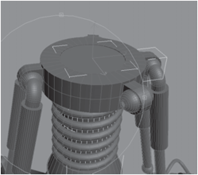
Figure 3-536

Figure 3-537
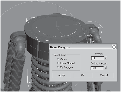
Figure 3-538
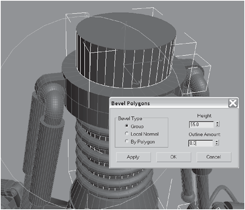
Figure 3-539
2. Create a Box on top of the cylinder and then convert it to an Editable Polygon.
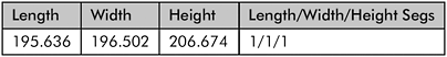

Figure 3-540

Figure 3-541
3. Create a Cylinder and position it over the corner of the box as shown. Convert it to an Editable Polygon, select the box, go to the Create panel and select Compound Objects, and then click the Boolean button.
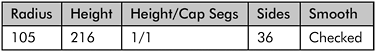

Figure 3-542

Figure 3-543

Figure 3-544
Figure 3-545
5. Select and Link the knee to the collar at the ankle (you could connect it to the cylinder, but it’s kinda hard to get to with the spring in the way). Move its pivot to the middle of the knee.
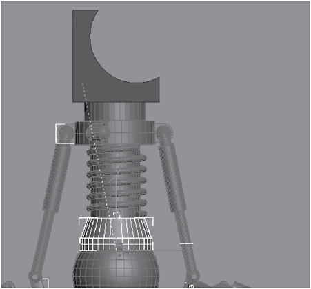
Figure 3-546
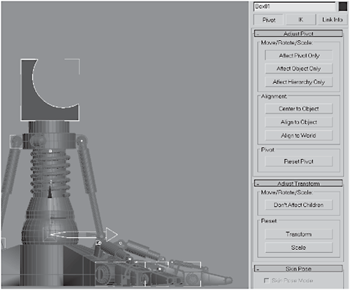
Figure 3-547
6. Use Rotate to angle the leg slightly back and then convert the knee from a Boolean to an Editable Polygon.
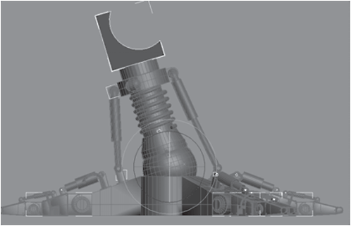
Figure 3-548

Figure 3-549
Figure 3-550
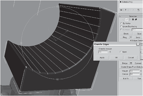
Figure 3-551

Figure 3-552

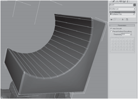
Figure 3-553
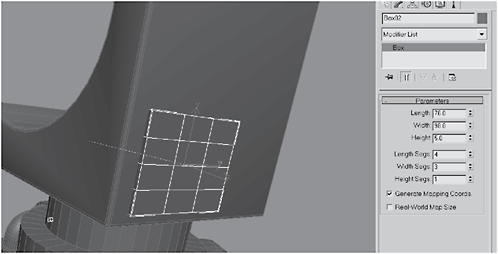
Figure 3-554
9. Convert the box to an Editable Polygon, select the top edges, and Chamfer them by 0.4 and then 0.14.
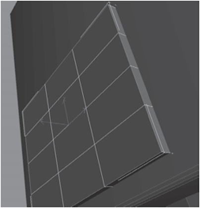
Figure 3-555
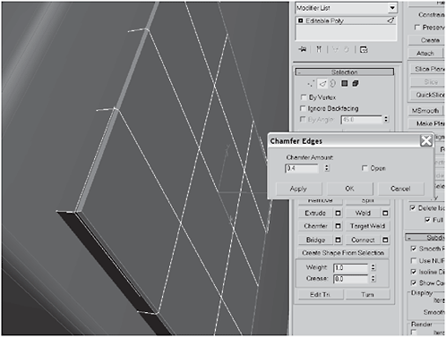
Figure 3-556
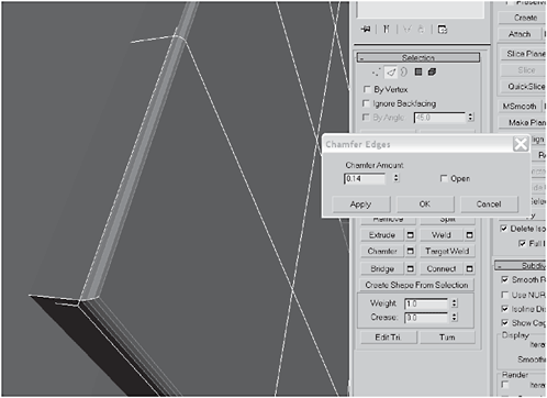
Figure 3-557
10. Select the two polygons as shown in Figure 3-558 and Bevel them:
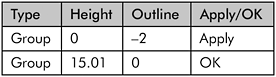

Figure 3-558

Figure 3-559
11. Select the lower middle polygon as shown and Bevel it:

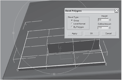
Figure 3-560

Figure 3-561
12. Create a Cylinder on the polygon you extruded in the previous step, and then convert the cylinder to an Editable Polygon.


Figure 3-562
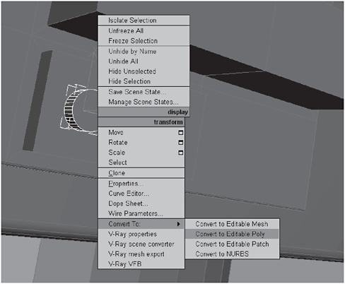
Figure 3-563
13. Select the cylinder cap and Extrude it 1.0 10 times. Move the pivot point to the edge just before the extrusions.
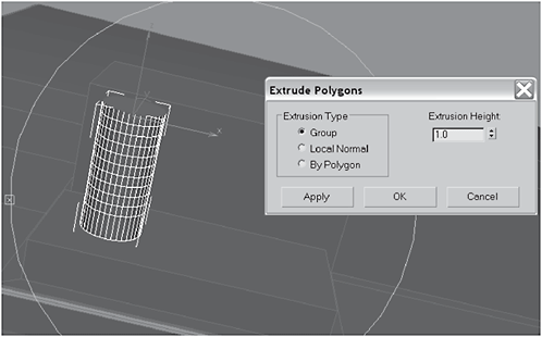
Figure 3-564
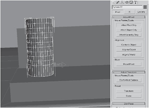
Figure 3-565
14. Add a Bend modifier with an Angle of 90 and a Direction of –90 to the stack. Click the Limit Effect check box and set the Upper Limit to 9.8. Right-click and convert the pipe to an Editable Polygon.
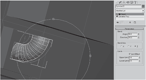
Figure 3-566
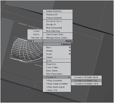
Figure 3-567
15. Use the Move tool to position the edge of the pipe just below the surface of the box. Select the cylinder cap and use the Move tool to stretch it up under the upper edge of the upper box.

Figure 3-568
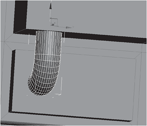
Figure 3-569
16. Make two clones of the pipe, position them as shown, and Select and Link them to the box above.

Figure 3-570

Figure 3-571

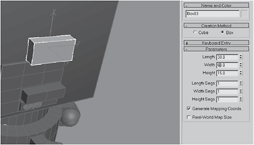
Figure 3-572

Figure 3-573
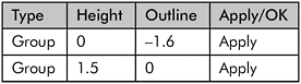
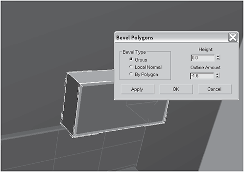
Figure 3-574
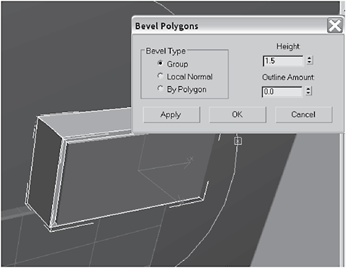
Figure 3-575

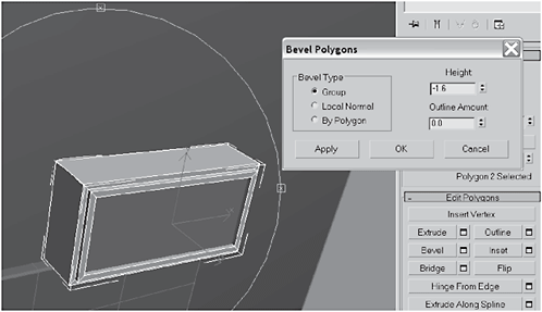
Figure 3-576
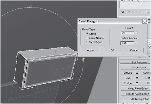
Figure 3-577
19. Click Tessellate and hit Apply five times, then hit OK. Click Bevel Settings:

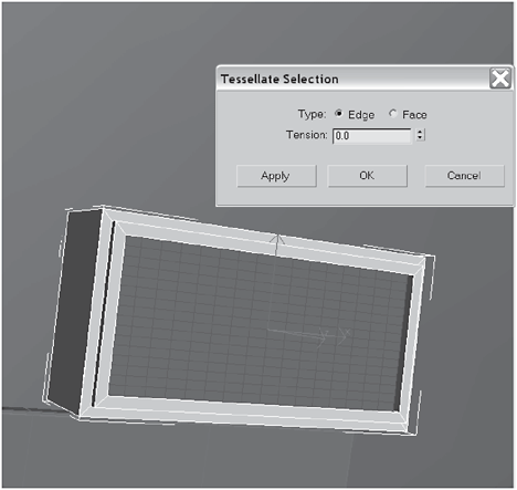
Figure 3-578
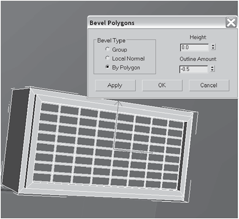
Figure 3-579
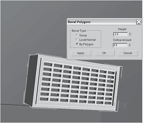
Figure 3-580
20. Create a Cylinder and clone it three times.
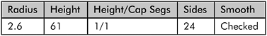

Figure 3-581
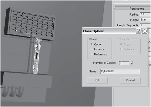
Figure 3-582
 FYI: You can put the pipes wherever you like. There is nothing special about where I placed them, other than I thought it was more visually interesting to place them opposite the bent pipes.
21. Select all the pipes and Select and Link them to the knee. Create a GeoSphere with a Radius of 5, 2 Segments, and a Type of Icosa.

Figure 3-583
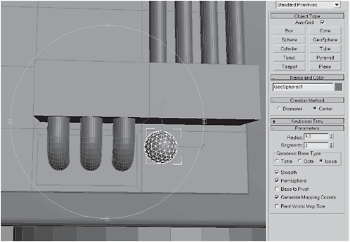
Figure 3-584
22. Convert the geosphere to an Editable Polygon and polygon-select the entire object. Click Bevel Settings:

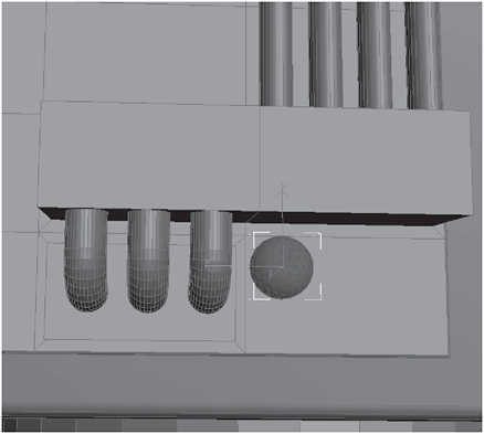
Figure 3-585

Figure 3-586

Figure 3-587
23. Create a Tube to the left of the boxes above the curved pipes. (Note: The location of this object is important.) Name the tube lower_knee_ hydraulic01.
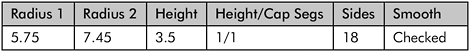
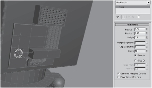
Figure 3-588
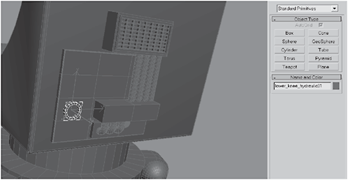
Figure 3-589
24. Create a Dummy and center it in the tube you just created, and name it calf_hydraulic_link_front. Clone the dummy and move it down to the hemispheric mount on the left side, and name it lower_knee_hydraulic02.
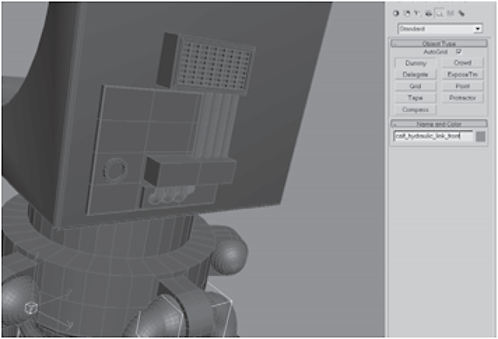
Figure 3-590
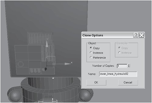
Figure 3-591
25. Create a Hose, switch the End Point Method to Bound to Object Pivots, and set the Top Binding Object to lower_knee_hydraulic, and the Bottom Binding Object to to calf_hydraulic_link_front.
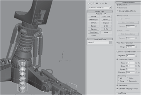
Figure 3-592
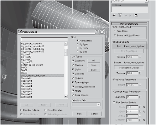
Figure 3-593
26. Set the hose type to Round, the Diameter to 9.242 and the number of Sides to 18. Using AutoGrid, create a Tube on the left front control piston, and name the tube front_foot_piston-nozzle. Select and Link the tube to the piston.


Figure 3-594

Figure 3-595
27. Create a Dummy on the front side of the hemisphere you connected the hose to in the last step, and name the dummy front_hose_conduit. Create another Hose.
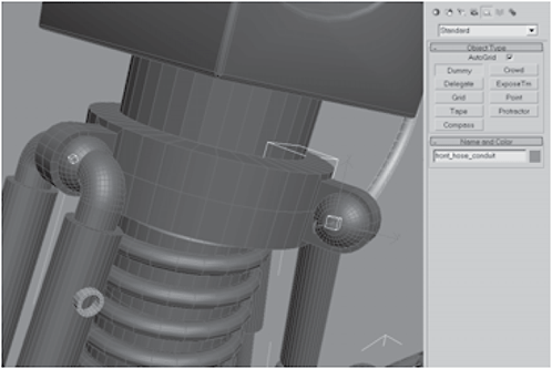
Figure 3-596
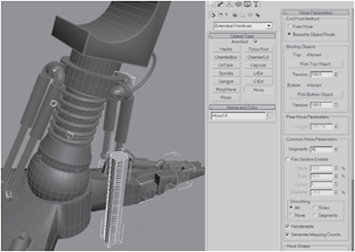
Figure 3-597
28. Set the Top Binding Object to front_hose_conduit and the Bottom Binding Object to front_foot_piston-nozzle. Set the hose to be Round and set both the Diameter and Sides to 12.
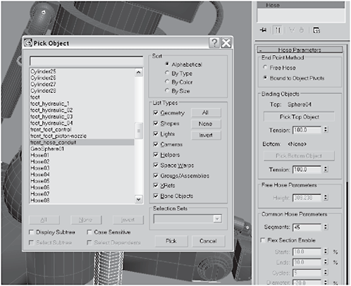
Figure 3-598
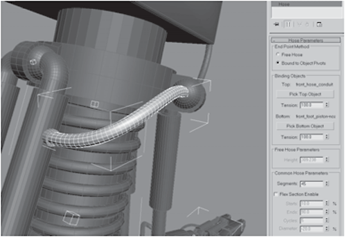
Figure 3-599

Figure 3-600
29. Create a Dummy on the right rear hemisphere, name it rear_foot_ hydraulic, and create another Hose.

Figure 3-601
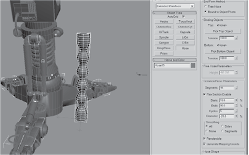
Figure 3-602
30. Set the hose’s Top Binding Object to the clone of the tube you made on the lower-right corner (lower_knee_hydraulic02). Set the Bottom Binding Object to the rear_foot_hydraulic, make the hose Round, and set the Diameter to 11 and Sides to 12. Create another Tube on the right rear control piston and name it rear_foot_ hydraulic_nozzle.


Figure 3-603

Figure 3-604
31. Create a Hose on the other side, using the same settings as in the previous step. Set its Top Binding Object to the rear_foot_hydraulic_nozzle. Set the Bottom Binding Object to the tube you made on the rear control piston in the previous step. Create a Cylinder in the kneecap you made using the Boolean object.
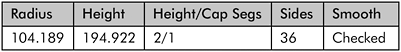
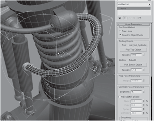
Figure 3-605
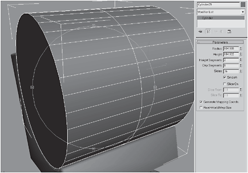
Figure 3-606
32. Convert the cylinder to an Editable Polygon and loop-select the middle edges. Chamfer the edges by 50.
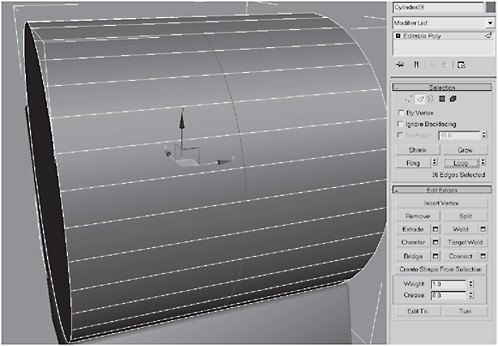
Figure 3-607

Figure 3-608
33. Select the middle polygons and Detach them as lower_knee_ hinge_middle.
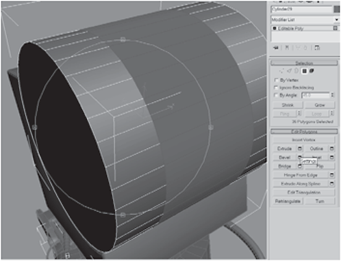
Figure 3-609
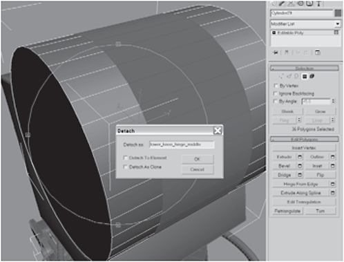
Figure 3-610
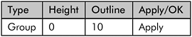
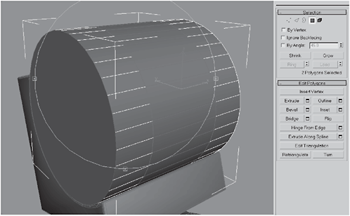
Figure 3-611
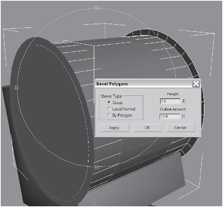
Figure 3-612

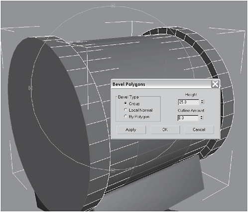
Figure 3-613

Figure 3-614


Figure 3-615

Figure 3-616

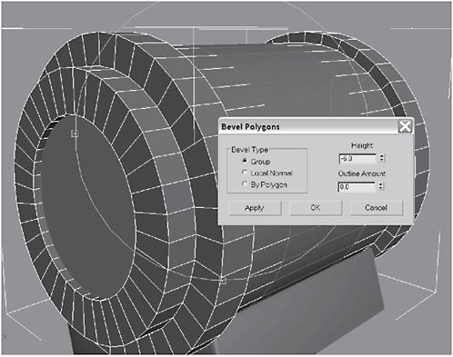
Figure 3-617
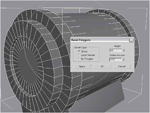
Figure 3-618

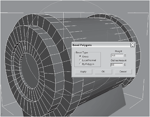
Figure 3-619
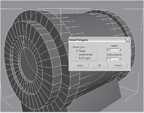
Figure 3-620


Figure 3-621
35. Using the Cut tool, make four slices in the top of the extrusion to form a cross. Be sure to do this on both the right and left sides of the knee.
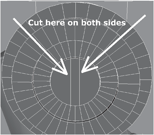
Figure 3-622
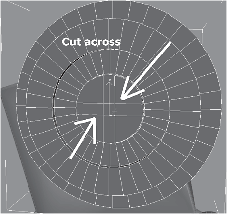
Figure 3-623
36. Select the outer four corners formed by the cuts, on both sides, and Extrude them by 10.

Figure 3-624

Figure 3-625
37. Element-select the parts of the knee shown in Figure 3-626 and Non-uniform Scale them 88 in the X axis so that they better fit in the indentation of the knee. Then border-select the borders of the middle part of the knee and stretch them until they close the gap with the outer parts of the knee.
Figure 3-626

Figure 3-627
Figure 3-628

Figure 3-629

Figure 3-630
39. Add a Smooth modifier to the stack and then convert to Editable Polygon to collapse the stack. Select the six middle polygons of the middle object and Extrude them by 13.
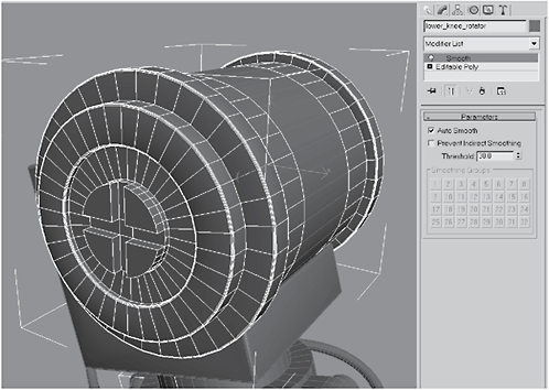
Figure 3-631

Figure 3-632
40. Extrude the polygons again by 13 to make a top stack. Select the polygons on both sides of the stack you extruded and extrude them by 72, so they just cover the outer rim of the knee.

Figure 3-633
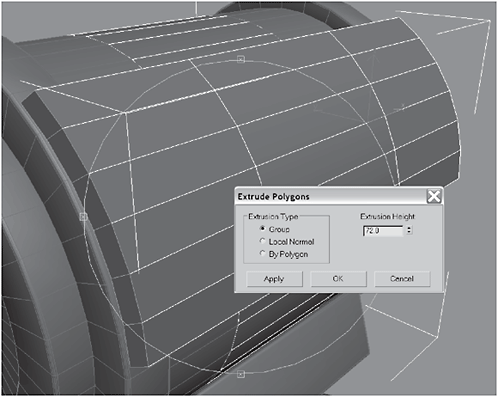
Figure 3-634
41. Select the top polygons and Non-uniform Scale them down to 0 in the Z axis to flatten them. Then Extrude the polygons by 100.

Figure 3-635

Figure 3-636

Figure 3-637

Figure 3-638
43. Select the bottom three rows of polygons and Extrude by Local Normal 120.
Figure 3-639

Figure 3-640

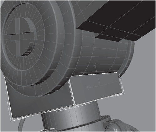
Figure 3-641
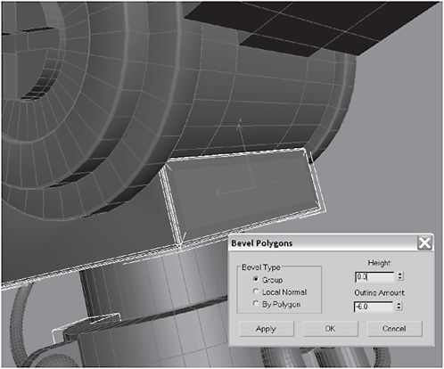
Figure 3-642

Figure 3-643

Figure 3-644

Figure 3-645

Figure 3-646
46. Select the polygons on the inside polygons and the bottom (so they form a 90-degree angle) and then Bevel them:

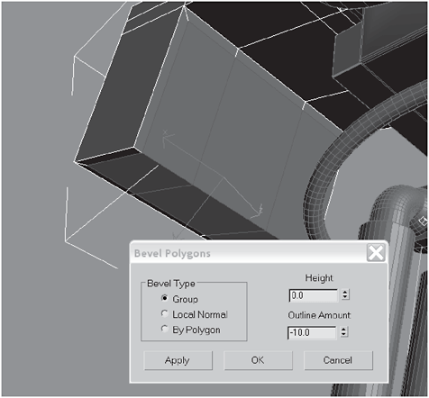
Figure 3-647
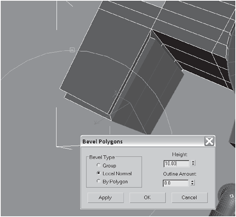
Figure 3-648
47. Create a Cylinder on the inside of the joint facing back toward the axle. Delete the polygon cap that touches the joint.
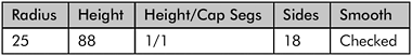
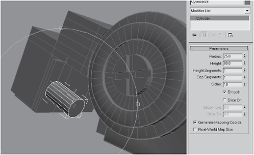
Figure 3-649
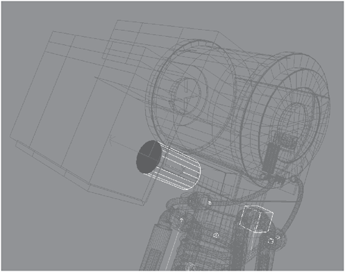
Figure 3-650
48. Select the border touching the kneecap, click Create Shape From Selection, and name it knee_piston_seal. Hit H and select knee_piston_seal from the list.
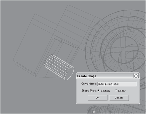
Figure 3-651

Figure 3-652
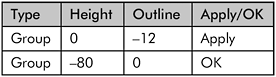

Figure 3-653
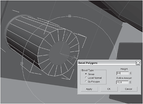
Figure 3-654

Figure 3-655

Figure 3-656
Figure 3-657
51. Add a Smooth modifier to the stack and then convert it to an Editable Polygon. Create two clones. Attach the clones to the original.
Figure 3-658
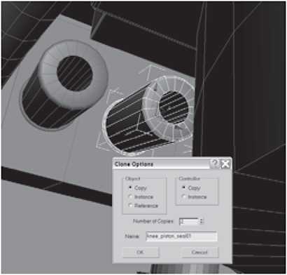
Figure 3-659

Figure 3-660
52. Select the three internal polygons and Detach them as knee_piston_shafts. Hit the H key and select knee_piston_shafts.
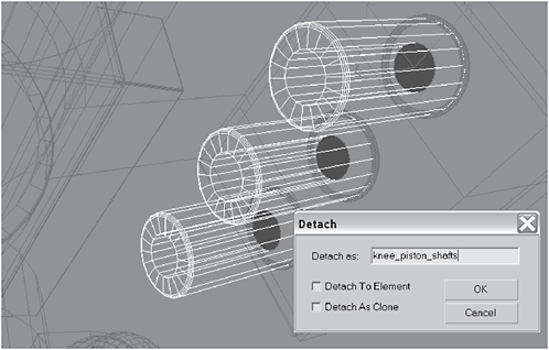
Figure 3-661

Figure 3-662
53. Pull them out of the pistons by moving them in the Z axis.
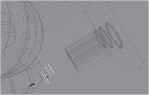
Figure 3-663

Figure 3-664
54. Use the Move tool to move them into place, border-select them, and then Extrude the edges by –180 to create the shafts that will enter the pistons. Select the shafts and pistons, right-click, and select Hide Unselected.
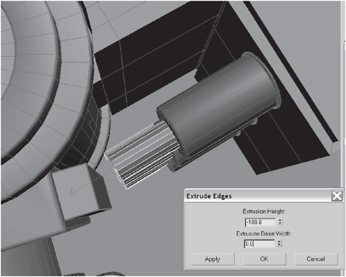
Figure 3-665
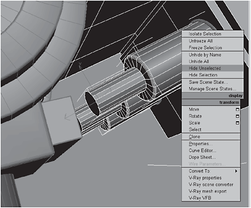
Figure 3-666
55. Use the Cut tool to cut the ends of the shafts as shown in Figure 3-667. Edge-select the cuts you just made, and use the Connect tool to connect them as shown in Figure 3-668.

Figure 3-667
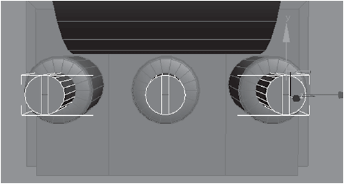
Figure 3-668
56. Select the polygons you made from the cuts and Extrude them by 15.

Figure 3-669

Figure 3-670
57. Select the bottom polygons and delete them. Select the top polygons and Hinge From Edge 180 degrees with 10 Segments, using the middle edge as the hinge. Delete the back-facing polygon. Select the vertices and Weld them before adding a Smooth modifier to the stack and then converting to an Editable Polygon object to collapse the stack.
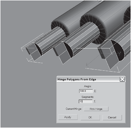
Figure 3-671

Figure 3-672
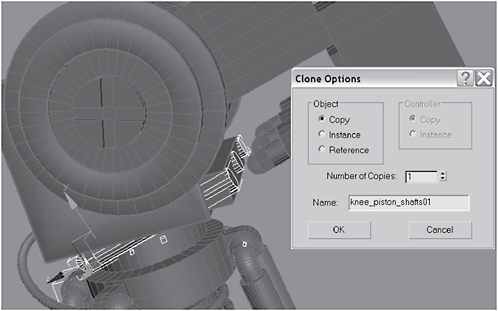
Figure 3-673
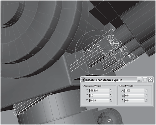
Figure 3-674
59. Make sure the rounded parts of the shafts overlap exactly and then delete the rounded parts of the clones to make a notch. Select the original, right-click, and choose Hide Selection.
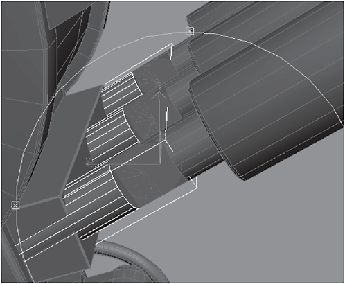
Figure 3-675

Figure 3-676
60. Border-select the open parts of the shafts and Cap them. Unhide the pistons and then select them and the shafts.

Figure 3-677
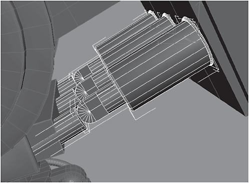
Figure 3-678
61. Scale the pistons and the shafts until they comfortably fit beneath the knee (don’t worry about the length of the shafts). Border-select the ends of the shafts and use the Move tool to reduce their length until their ends are completely within the joint.
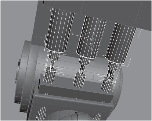
Figure 3-679

Figure 3-680
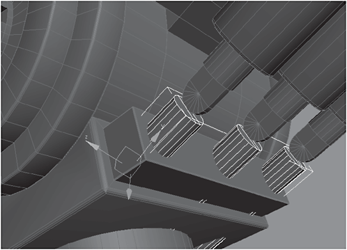
Figure 3-681

Figure 3-682
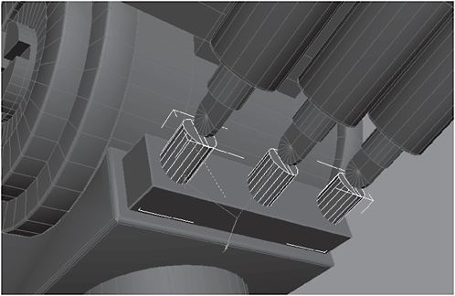
Figure 3-683
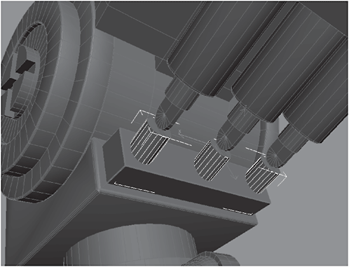
Figure 3-684

Figure 3-685
63. Add a Smooth modifier to the stack of shafts and then convert to an Editable Polygon to collapse the stack. Choose Affect Pivot Only and position it on the center of the middle shaft.
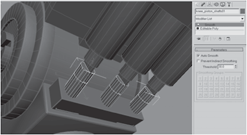
Figure 3-686
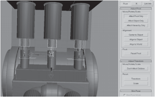
Figure 3-687
64. Create a Dummy, position it roughly in the center of the three pistons, and name it lower_knee_piston_dummy. Use Align Selection to center the dummy on the center of the pistons.
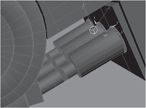
Figure 3-688

Figure 3-689
65. Select and Link the dummy to the pistons and then add a LookAt controller to the shaft’s Rotation controller.
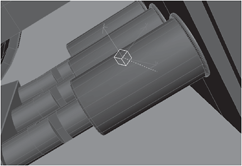
Figure 3-690

Figure 3-691
66. Assign the LookAt Target to lower_knee_piston_dummy. Set the LookAt Axis to Z and click the Flip check box. Set the Upnode Control to LookAt and the Source Axis to Y.
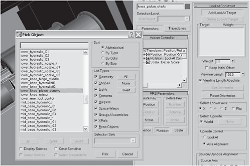
Figure 3-692

Figure 3-693
Day 7: Assembling the Upper Leg
1. Select the front three polygons shown in Figure 3-694 and Extrude them by 180 and then select the top three edges.

Figure 3-694
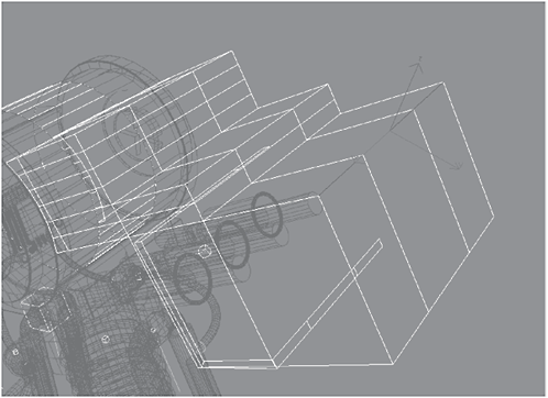
Figure 3-695
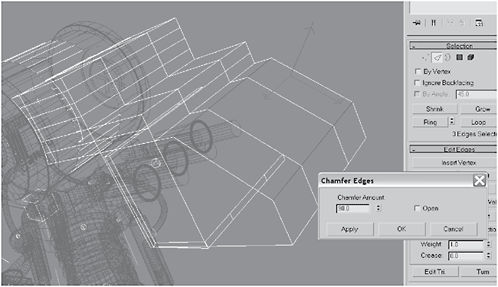
Figure 3-696

Figure 3-697
3. Extrude the three polygons by Local Normal to a Height of 48. Select the top 10 rows of polygons.

Figure 3-698
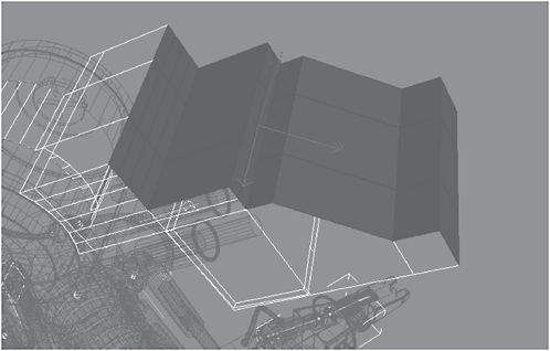
Figure 3-699
4. Click Detach, name it upper_knee_cowl, and click the Detach As Clone check box. Select the top three edges and Extrude them by 397.
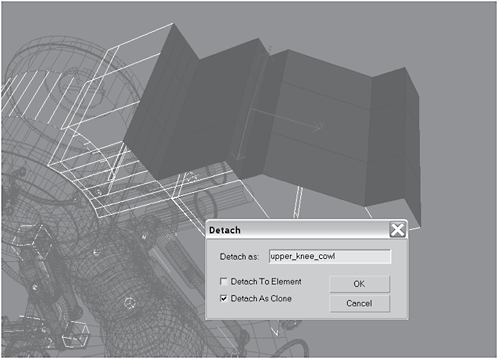
Figure 3-700
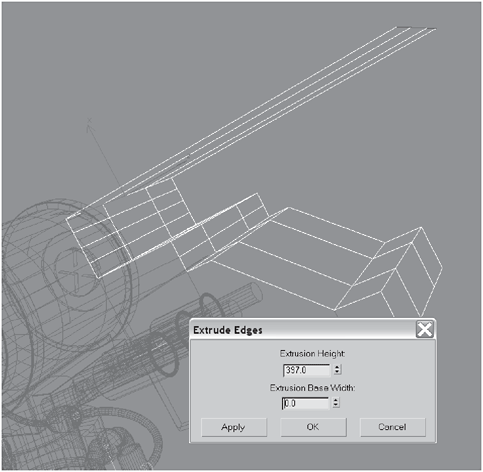
Figure 3-701
5. Hold down the Shift key and drag the edge downward until it is aligned with the bottom edge of the upper_knee_cowl (~221 units). Hold down the Shift key, select the three edges on the bottom of the upper_knee_cowl, and click the Bridge button (in the Edit Edges rollout).
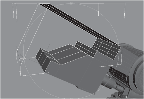
Figure 3-702
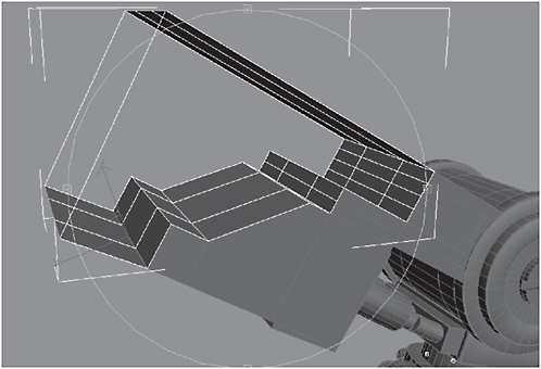
Figure 3-703
6. Switch to Polygon selection and select the polygons on the top and front inside surfaces, then click the Grow button (in the Selection rollout) until all the inner surface polys have been selected. Right-click and select Flip Normals (it’s the last selection on the menu). Border-select the outer edges.
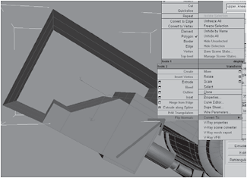
Figure 3-704

Figure 3-705
7. Border-select both sides and Cap them. Create a Cylinder and position it in the upper corner of the new joint.

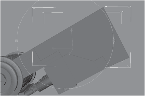
Figure 3-706

Figure 3-707
8. Select the cylinder and convert it to an Editable Polygon. Loop-select the middle edges on the cylinder.
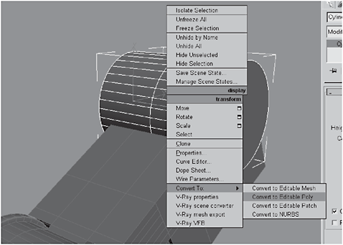
Figure 3-708
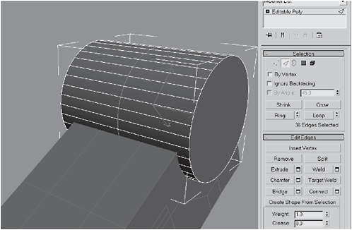
Figure 3-709
9. Chamfer the edges (around 50.3) until they are aligned with the edges on the leg. Move the cylinder until the chamfered edges on the cylinder line up with the edges on the upper_knee_cowl. In order to make a socket for the knee, select the upper_knee_cowl, create a Boolean object (select Compound Object in the Create panel and click the Boolean button), click Pick Operand B, click the cylinder (Cylinder29), and choose Subtraction (A–B).
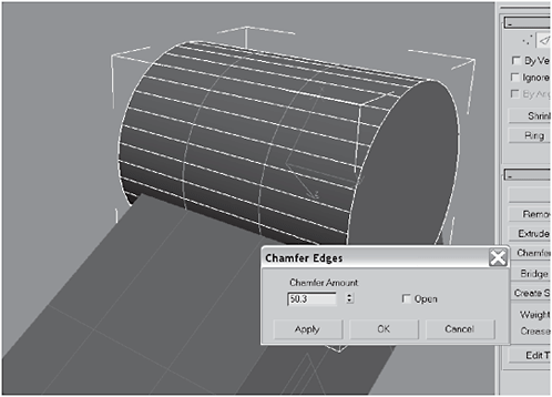
Figure 3-710

Figure 3-711
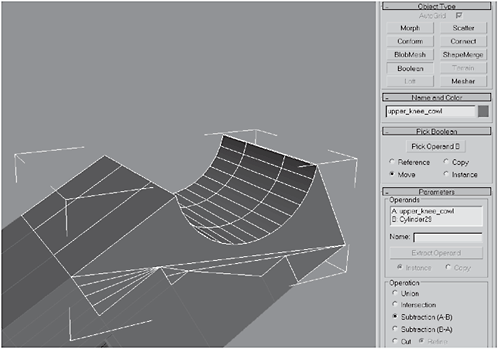
Figure 3-712
10. Select the Boolean object and convert it to an Editable Polygon. Select any extra edges made on the outer surfaces by the Boolean operation and click Remove. (Note: Depending on where you positioned the cylinder, you may have more or fewer edges than those shown in my figures.)

Figure 3-713

Figure 3-714

Figure 3-715
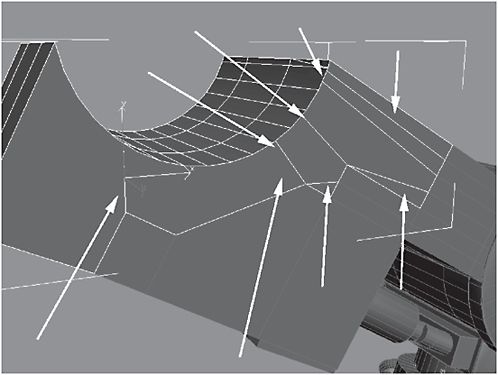
Figure 3-716
11. Select and Remove, or Target Weld, the isolated vertices indicated in the following figures, then continue to remove isolated, unnecessary edges and vertices.
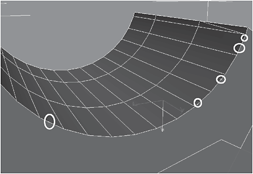
Figure 3-717

Figure 3-718
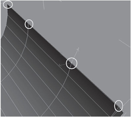
Figure 3-719
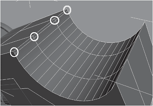
Figure 3-720
12. Select all the vertices in the upper_knee_cowl and click the Weld Settings button. Set the Weld Threshold fairly high (around 1.25) and click Weld to weld any overlapping vertices you may’ve missed. Select upper_knee_cowl and add a Smooth modifier to the stack, making sure to check the Auto Smooth check box. Convert it to an Editable Polygon to collapse the stack, then select the outer edges.
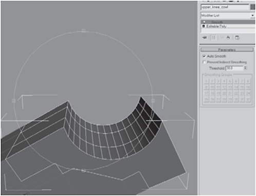
Figure 3-721

Figure 3-722

Figure 3-723
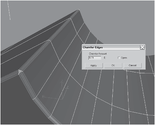
Figure 3-724
14. Select the inside surface, click Detach, and name the new object knee_sleeve.

Figure 3-725
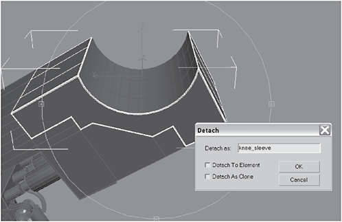
Figure 3-726
15. Do a quick render. If there is a problem with the outer surface, try selecting the cap and deleting it and then recapping it. That should work.

Figure 3-727
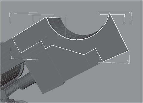
Figure 3-728

Figure 3-729
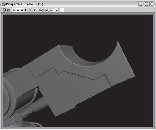
Figure 3-730
 Fire Drill: So why did that happen, and why did simply deleting the cap and adding it back fix it? Don’t know. Most people hate to use Booleans because they can result in unpredictable outcomes. Sometimes, as in this case, Booleans are the only way to get the shape you’re looking for. In those cases, expect to suck it up and do some fixing. Incidentally, this problem with Booleans is not unique to Max. It’s the same with every 3D package I’ve used.
16. Create a Cylinder in the joint and loop-select the middle edges of the cylinder.
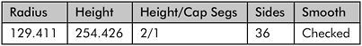

Figure 3-731
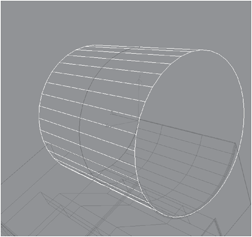
Figure 3-732
17. Chamfer the edges until they line up perfectly with the edges on the joint below (in my case it was 49.538). Select the middle polygons and Detach them as upper_knee.

Figure 3-733

Figure 3-734
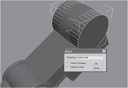
Figure 3-735
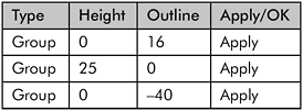
Figure 3-736
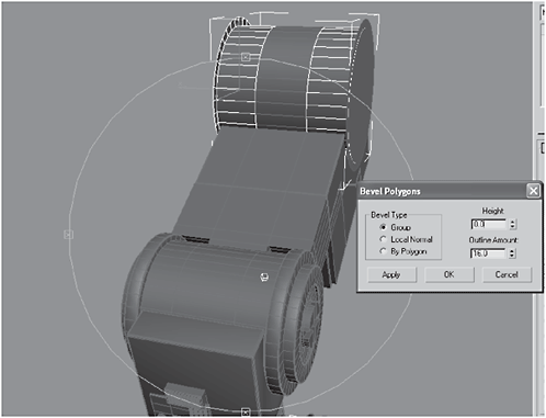
Figure 3-737
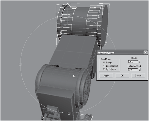
Figure 3-738
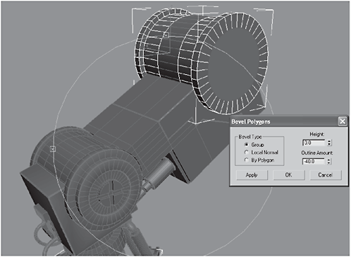
Figure 3-739
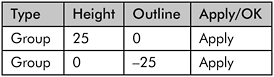
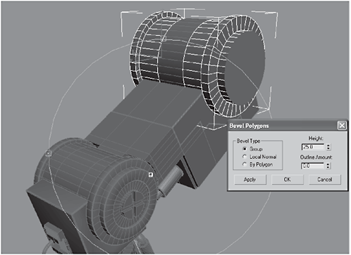
Figure 3-740
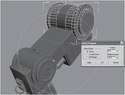
Figure 3-741

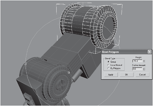
Figure 3-742
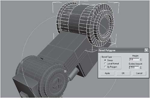
Figure 3-743
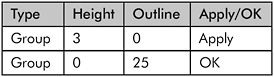
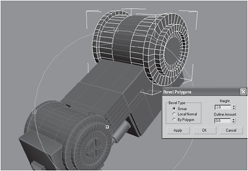
Figure 3-744
19. Cut four slices to form a cross, then select the outer four corners and Extrude them by 10. You do this the same way you did for the lower knee, in steps 35 and 36 of the previous section (Day 6).
20. Select the outer edges of the kneecaps and Chamfer them by 3.5 and then by 1.41.
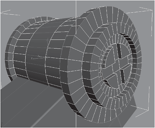
Figure 3-745
Figure 3-746

Figure 3-747
21. Add a Smooth modifier to the stack, convert it to an Editable Polygon to collapse the stack, and add a Tube named upper_knee_ hydraulic_valve:

Figure 3-748
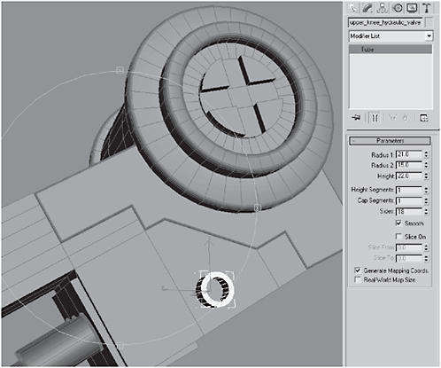
Figure 3-749
22. Create a Tube on the piston closest to the tube you just created, and name it three_piston_feeder_valve. Select and Link it to the piston. Create a new Hose.
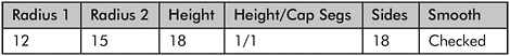

Figure 3-750
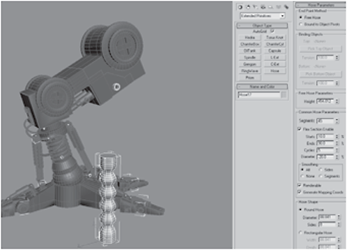
Figure 3-751
23. Change the End Point Method to Bound to Object Pivots, set the Top Binding Object to upper_knee_hydraulic_valve, and set the Bottom Binding Object to three_piston_feeder_valve.

Figure 3-752

Figure 3-753
24. Set the top Tension to 191, leave the bottom Tension at 100, and change the hose Diameter to 22.541 with 16 Sides. Change the upper_knee_hydraulic_valve’s Radius 2 to 11.858.
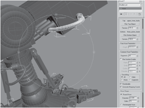
Figure 3-754

Figure 3-755
25. Make two clones of the upper_knee_hydraulic_valve, Rotate them, and move them to the far bottom surface of the knee (at right angles to the three pistons). Select three_piston_feeder_valve and make two clones.

Figure 3-756

Figure 3-757
26. Move the clones you just made, Rotate them 90 degrees, and apply them to the far two pistons that do not, as yet, have valves attached to them. Select and Link them to the pistons. Create another Hose with the End Point Method set to Bound to Object Pivots.

Figure 3-758

Figure 3-759
27. Set the Top Binding Object to the upper_knee_hydraulic_valve and set the Tension to 169. Set the Bottom Binding Object to three_piston_feeder_valve and set the Tension to 138. Set the Diameter of the hose to 18.647 and the Sides to 16. Select the eight polygons on the center of the upper knee as shown in Figure 3-761.
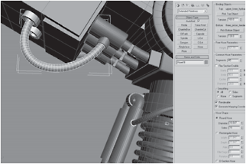
Figure 3-760
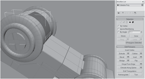
Figure 3-761

Figure 3-762

Figure 3-763
29. Select the side polygons of the top row of the extrusion and Extrude them by 92.15.

Figure 3-764

Figure 3-765
30. Select the top polygons of the extrusion, set the Coordinate System to Local, and then Non-uniform Scale them down to 0 in the Z axis.
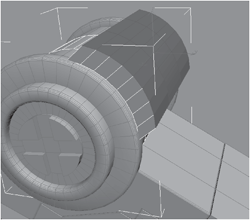
Figure 3-766
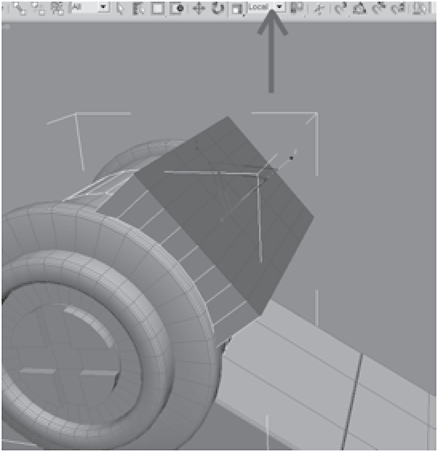
Figure 3-767
31. Extrude the polygons by 180 and select only the polygons in the last three rows as shown in Figure 3-769.
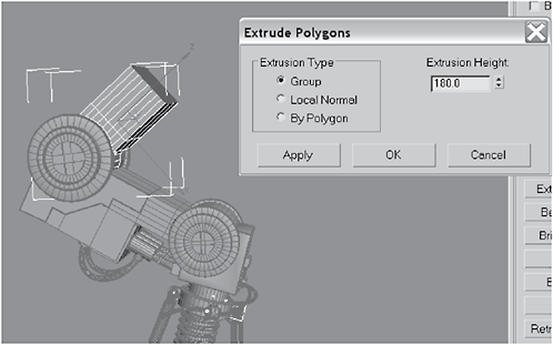
Figure 3-768
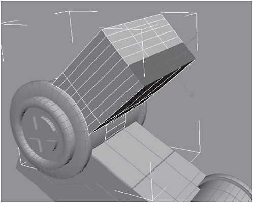
Figure 3-769
32. Extrude the polygons by 150 and then select the three polygons on the bottom of the extrusion.
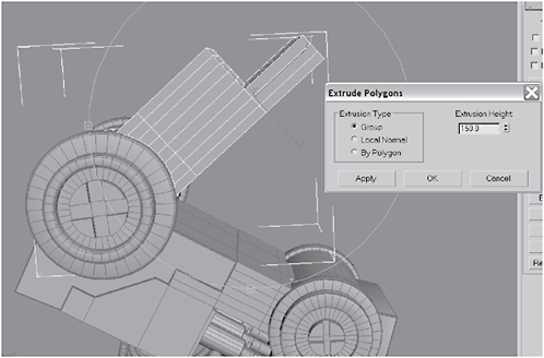
Figure 3-770

Figure 3-771
33. Extrude the polygons by 120. Select the front three lower bottom polygons, as shown in Figure 3-773.
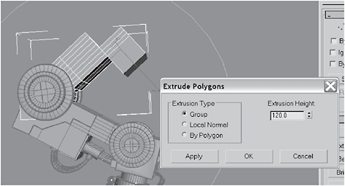
Figure 3-772
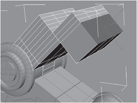
Figure 3-773

Figure 3-774
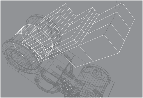
Figure 3-775
35. Chamfer the edges by 90 and then select the lower front three polygons.

Figure 3-776
Figure 3-777
36. Extrude those three polygons by 50 and then select the top polygons the way you did before.
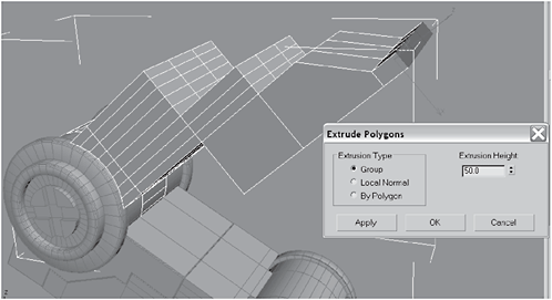
Figure 3-778

Figure 3-779
37. Detach the polygons and name it upper_thigh. Select the top upper three edges, as shown in Figure 3-781.
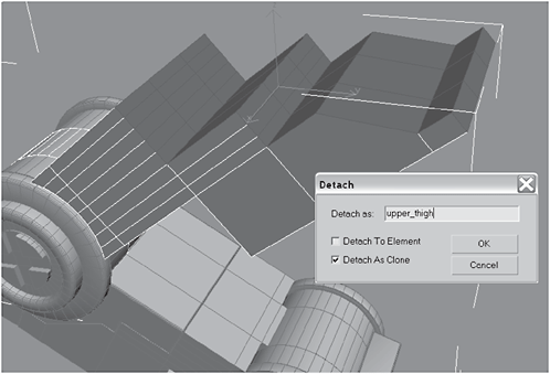
Figure 3-780

Figure 3-781
38. Extrude the edges by 550 and then drag them downward like you did before.

Figure 3-782

Figure 3-783
39. Select the two outer rows of edges and then click Bridge.

Figure 3-784

Figure 3-785
40. Select the inside polygons, like you did previously, and Flip them. Border-select the outer borders and Cap them.

Figure 3-786

Figure 3-787
41. Create a Cylinder in the upper corner and convert it to an Editable Polygon. Use Loop to select the middle edges, as you did before, and chamfer them by about 48 (or until they’re aligned with the edges on the upper_thigh). Select the upper_thigh,createa Boolean object, choose Subtraction (A–B), click Pick Operand B, and then click the cylinder. Remove the extra edges created by the Boolean operation the way you did before. (Don’t forget to remove the residual vertices.)
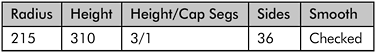
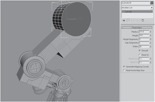
Figure 3-788
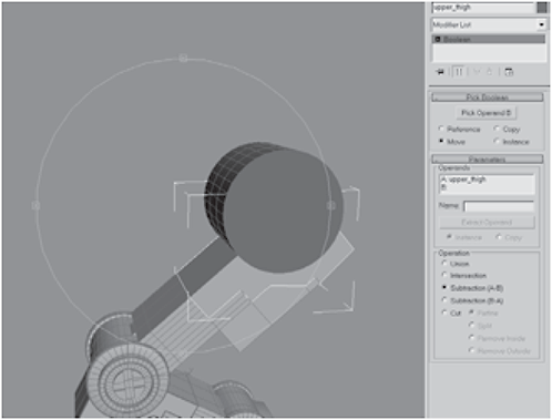
Figure 3-789
42. Select the Boolean object and convert it to an Editable Polygon. Create a Chamfer Cylinder in the socket created by the Boolean.
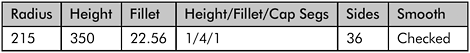

Figure 3-790
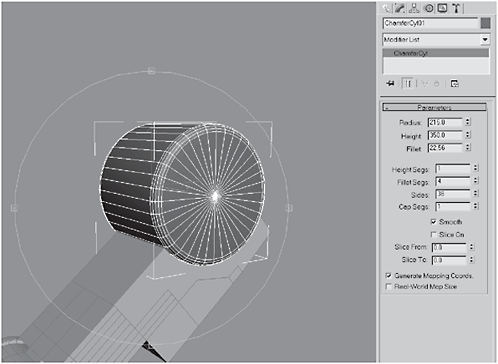
Figure 3-791
43. Convert the chamfer cylinder to an Editable Polygon and name it Hip. Polygon-select the outside cap only.
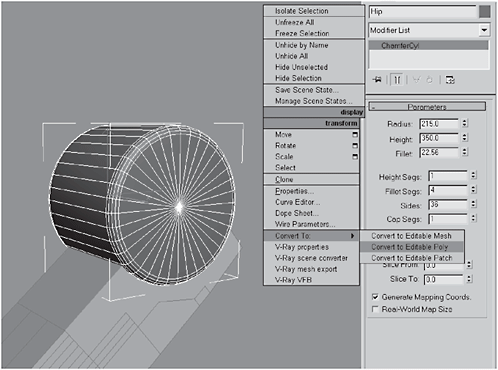
Figure 3-792
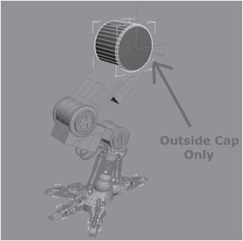
Figure 3-793
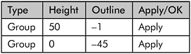

Figure 3-794
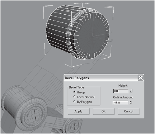
Figure 3-795

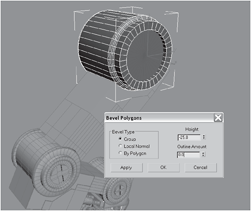
Figure 3-796
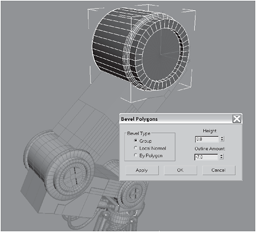
Figure 3-797
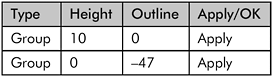

Figure 3-798

Figure 3-799


Figure 3-800
45. Delete the cap. Using AutoGrid, create a Sphere with a Radius of 88.418 and 36 Segments, and set Hemisphere to 0.5. Align the segments, convert it to an Editable Polygon, and name the hemisphere axle_cap.
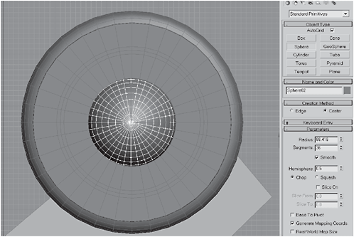
Figure 3-801
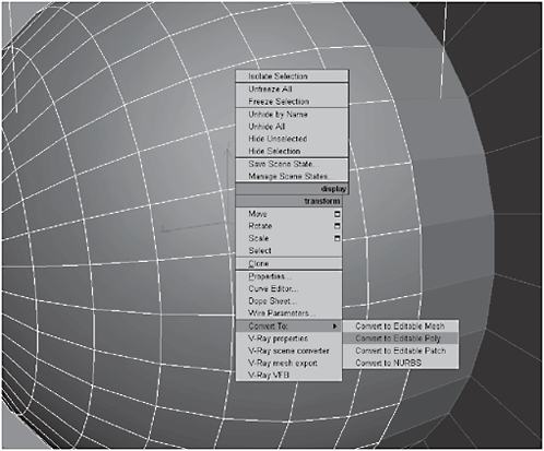
Figure 3-802
46. Select the back-facing polygons of the hemisphere and delete them. Align the segments of the hemisphere with those of the chamfer cylinder, select the chamfer cylinder, click Attach, and select axle_cap.

Figure 3-803
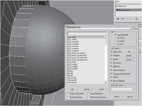
Figure 3-804
47. Create a Gengon and name it lugnut. Click the Hierarchy tab, select Affect Pivot Only, and move the pivot to the center of the axle_cap.
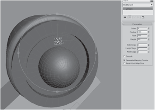
Figure 3-805

Figure 3-806
48. Hold down the Shift key, Rotate by 40, and set the Number of Copies to 8. Select the chamfer cylinder, click Attach List, select all lugnut clones, and click Attach.

Figure 3-807

Figure 3-808
49. Select and Link the chamfer cylinder to the upper_thigh. Select the two outer polygons on the top of the middle leg.

Figure 3-809

Figure 3-810

Figure 3-811

Figure 3-812
51. Extrude the polygons by Local Normal –70. Select the matching two polygons on the upper leg and Bevel them:


Figure 3-813
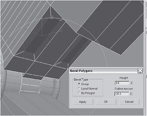
Figure 3-814
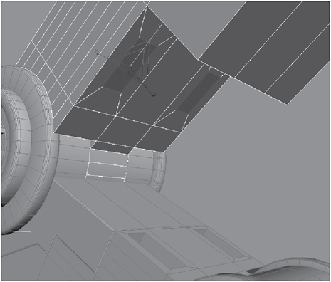
Figure 3-815
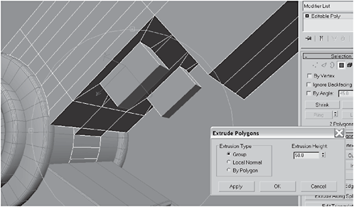
Figure 3-816
53. Extrude the polygons by 10 and hit Apply 20 times and then hit OK. Hit Grow until the entire group of extrusions has been selected, click Detach, and name it lifter_gears.

Figure 3-817
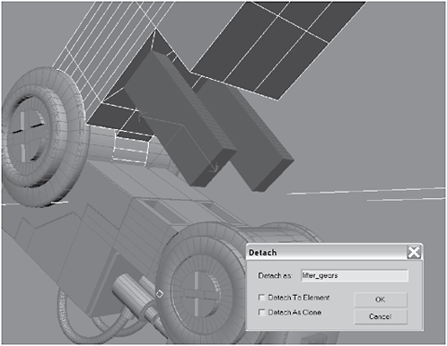
Figure 3-818
54. Select and Link the lifters to the top leg. Move the pivot point to the first segment.

Figure 3-819
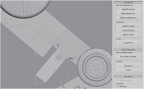
Figure 3-820
55. Add a Bend modifier to the stack with an Angle of 60 and a Bend Axis of Y, check Limit Effect, and set the Lower Limit to –147.277.
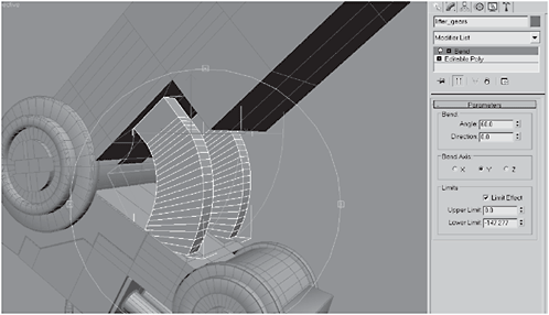
Figure 3-821
FYI: This is an iterative process. Unless you are a lot better than meat visualizing how long and wide these lifters have to be once the Bend modifier is attached, then you, like me, will need a couple of tries to get it right. The important thing is to not collapse the stack right away. Click the Editable Polygon node beneath the Bend modifier, roll it out, and tweak the subobjects, switching back and forth between the Editable Polygon level and the Bend level in the stack until you get a good fit. What follows is what I did. This not the “right” way or the “ best” way. It is just one way. At this point, you should really start experimenting on your own, testing the limits of the tools. That’s the only way to achieve a deep understanding of the way the tools work, both individually and together.
56. I selected the bottom 20 extrusions and used the Move tool to move them around 40 in the Z axis to stretch the lifters to compensate for the shortening that occurs from the bend.
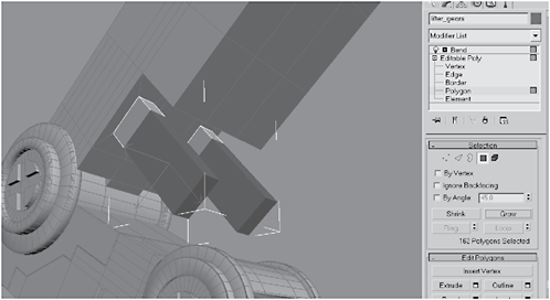
Figure 3-822

Figure 3-823
57. Click the Bend modifier in the stack and check the alignment. It’s better, but still not lining up perfectly with the holes. Non-uniform Scale the selection to 80 in the Y axis (so the ends of the lifters will be smaller and more easily fit into the holes.)
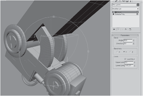
Figure 3-824
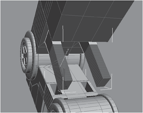
Figure 3-825
58. Under the Bend modifier, change the Lower Limit to –168.954. Switch to Non-uniform Scale and scale down to 80 in the Y axis again.

Figure 3-826

Figure 3-827
59. Switch back to the Bend modifier and check the fit. Change the Lower Limit to –159.48. Switch to Non-uniform Scale and scale down to 80 in the Y axis. With the Bend modifier still selected, scale the X axis to 91.

Figure 3-828

Figure 3-829
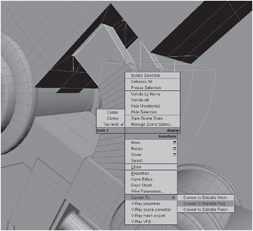
Figure 3-830
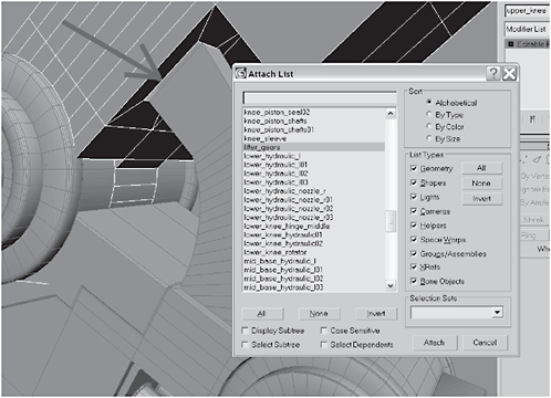
Figure 3-831
61. Select every other polygon and Bevel them:

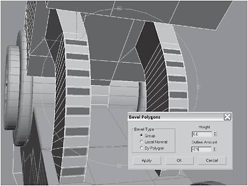
Figure 3-832
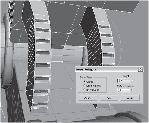
Figure 3-833
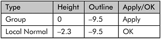

Figure 3-834

Figure 3-835
63. Extrude the polygons by –10. Add a Smooth modifier to the Hip and then convert it to an Editable Polygon.
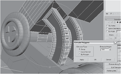
Figure 3-836

Figure 3-837
 Urgent: Before continuing, it is important that you evaluate the upper_thigh. Since you created it with a Boolean, it’s likely there are some problems that need fixing. Now is the time to fix them, before proceeding with the next few modeling steps.

Figure 3-838

Figure 3-839
65. Extrude the polygons to a Height of 6. Bevel them with the settings in the table below, Non-uniform Scale them to 50 in the Y axis, and Extrude them –0.1.

Figure 3-840

Figure 3-841
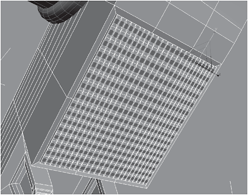
Figure 3-842
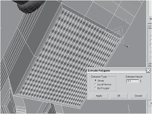
Figure 3-843
66. Click the MSmooth button and then Extrude by Local Normal –25.

Figure 3-844

Figure 3-845
67. Select the polygons shown in Figure 3-846, Bevel them, and then select the outer edges for chamfering.
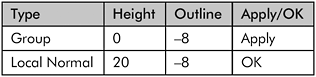

Figure 3-846

Figure 3-847
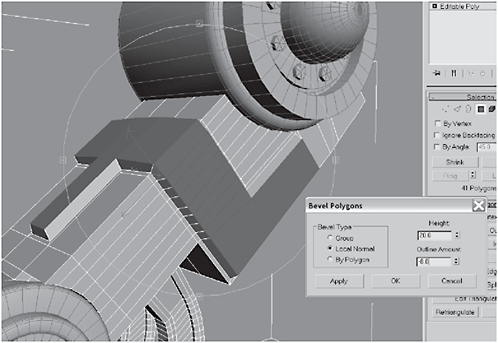
Figure 3-848

Figure 3-849
68. Chamfer the edges first by 3 and then by 1.32.

Figure 3-850

Figure 3-851
69. Create a Sphere with a Radius of 9.177, 16 Segments, and a Hemisphere of 0.5. Create 15 clones and position them as shown (or use your own layout), like rivets on the brace, and then Attach them to the brace.
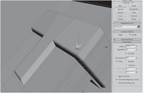
Figure 3-852

Figure 3-853
Figure 3-854

Figure 3-855
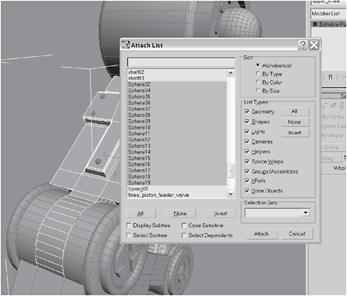
Figure 3-856
Day 8: Creating the Second Leg, Hips, and Base
1. If you haven’t already, delete the rivet. We won’t be needing it again. Hit the H key to open the selection list and click All. Click the Layer button on the Main toolbar. When the Layer Manager opens, click the Add Layer button.

Figure 3-857

Figure 3-858
2. Double-click on the new layer and name it left_leg. Make sure the left_leg layer is still selected and click the Add button (looks like a big + sign) to add the leg components to the new layer. With all the leg components still selected, select Group from the Main menu and name the new group left_leg.
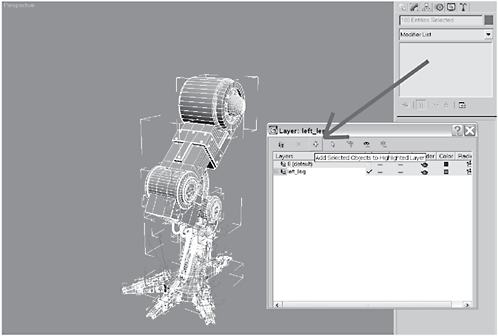
Figure 3-859
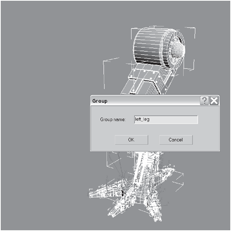
Figure 3-860
FYI: So what was the purpose of the last step? We’re getting to the point where there are so many polygons we’ll be starting to experience some slowdowns when we move in the viewport (maybe you’ve already experienced this). Putting the leg into a layer will allow us to hide it to speed up the display.
Adding all the parts of a group will make it easier to clone them to make a second leg. Grouping them will ensure that we don’t miss anything.
3. Switch to the Front view and, with the leg selected, click the Mirror button. Set the Mirror Axis to X, the Offset to –2000, and Clone Selection to Copy.
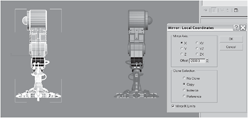
Figure 3-861

Figure 3-862
Urgent: You’ll notice that when you copied the leg, your constraints and hoses they got … um … what’s the technical term? Jacked up. Fortunately, it’s not difficult to fix, but it’s a major pain.
4. Ungroup the clone. Select the mid_base_hydraulic on the foot of the clone, as shown. Open the Hierarchy tab and go to the Adjust Transform rollout. Under Reset click the Transform button. Click the Reset Pivot button to reset the tube’s pivot point and click Center to Object.

Figure 3-863
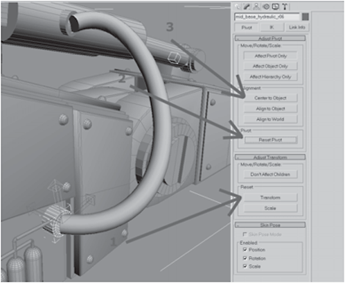
Figure 3-864
FYI: Rather than realigning the pivots, I find it easier to just delete the hose and create a new one; especially since hoses are not that difficult to make. As you know from doing the original foot, realigning the pistons and shafts can represent more of a challenge.
5. Make sure the pivots for the Top and Bottom binding objects are identically aligned, with the blue Z axis facing out and away from the foot, the red X axis facing downward, and the green Y axis pointing forward; this will make binding the new hose easier. Create a new hose. Set the Top and Bottom tensions to 45. Choose Bound to Object Pivots and choose lower_hydraulic_nozzle for the Top Binding Object and mid_base_hydraulic for the Bottom Binding Object.
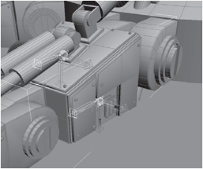
Figure 3-865
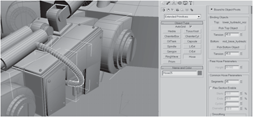
Figure 3-866
Fire Drill: Because there are so many hoses and pistons to realign, for space reasons, I’ll leave you to realign them yourself. The process for hoses is identical to what you’ve just done. As for the pistons, the process is identical to the fixes you made at the beginning of Day 4.
6. Ungroup the original leg. Select the original Hip, click Attach List, select Hip01 (the clone), and click Attach.

Figure 3-867

Figure 3-868
7. Select the hips and the upper legs of both legs. Right-click, choose Hide Unselected, and then select the inner 36 polygons on both hips.

Figure 3-869

Figure 3-870


Figure 3-871

Figure 3-872
9. Switch to the Front view. Create a Sphere using AutoGrid with a Radius of around 200 and 36 Segments. Rotate it 90 degrees, so the top faces the other leg as shown. Move the sphere into the hole created by deleting the polygons and adjust its Radius (~198) until the segments on the sphere align with the segments on the Hip, as shown. (Note: The sphere is situated so that two rings of segments below the centerline meet the edge of the Hip. This will be important for welding).
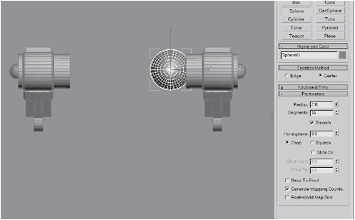
Figure 3-873

Figure 3-874
10. Switch to wireframe (F3) and select and delete the polygons of the sphere that lie below the surface of the Hip. Object-select the sphere, Mirror it in the X axis, and make a copy.

Figure 3-875
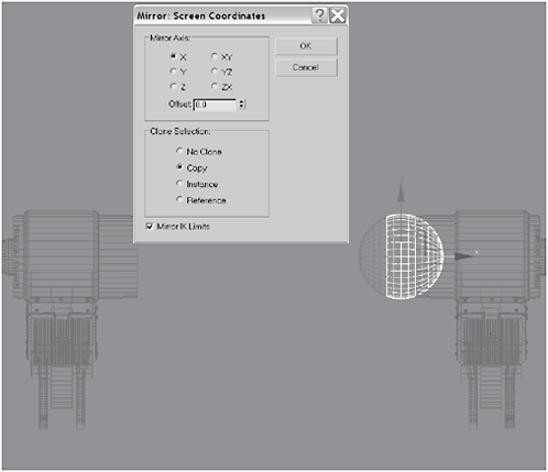
Figure 3-876
11. Move the clone to the other Hip as shown. Select the Hips and attach the spheres to create a hip joint.
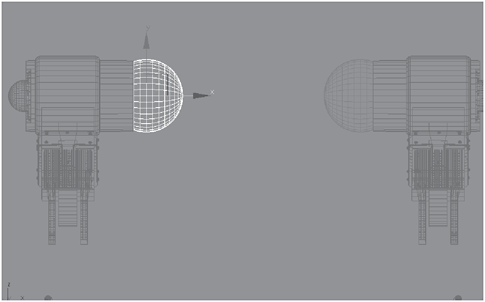
Figure 3-877
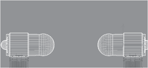
Figure 3-878
12. Vertex-select the vertices where the sphere connects with the Hip and then click Weld . (You’ll probably need to increase the Weld Threshold; watch the Before and After values and adjust the threshold until After is 36 less than Before.)
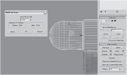
Figure 3-879
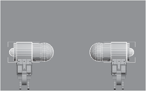
Figure 3-880
13. Create a Box between the legs and convert it to an Editable Polygon. Hide the box and then create a Sphere with a Radius of 200 and 36 Segments.

Figure 3-881

Figure 3-882
14. Rotate the sphere 90 degrees, then superimpose the sphere over the hip joint. Change the Radius to 204.304 (so that it is slightly larger than the hip joint), set Hemisphere to 0.5, and convert it to an Editable Polygon.
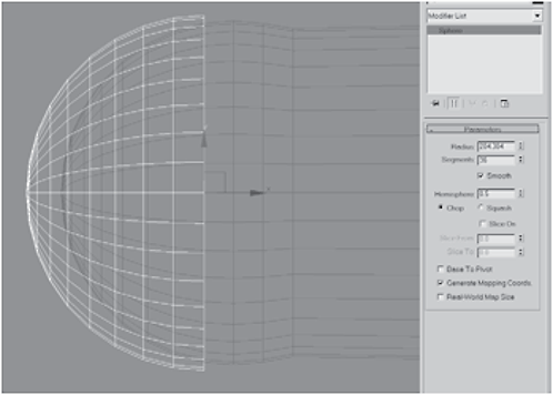
Figure 3-883
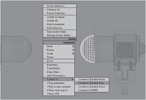
Figure 3-884
15. Mirror-copy the hemisphere in the X axis and set the Offset to –1100. Select both hemispheres, right-click, and click Hide Unselected so that only the hemispheres are visible.
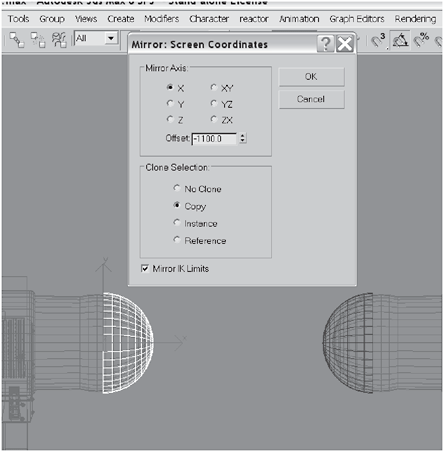
Figure 3-885

Figure 3-886
16. Switch to the Front view if necessary. Unhide the box and move the hemispheres until they are positioned as shown below, with their outer edges just above the surface of the box. Switch to the Perspective view and loop-select the vertical edges that separate the box into front and back pieces.

Figure 3-887

Figure 3-888
17. Chamfer the edges (~208) so that two edges are created (one on each side of the hemisphere). Loop-select the horizontal edges that separate the box into top and bottom sections.
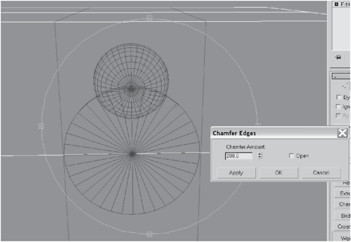
Figure 3-889

Figure 3-890
18. Chamfer the edges (~208) so that two edges are created (one on the top and one on the bottom of the hemisphere, forming a square with the edges you previously chamfered). Object-select the box, rename it Pelvis, and create a Boolean object.

Figure 3-891
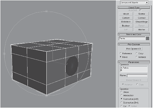
Figure 3-892
19. Click Pick Operand B and then select a hemisphere to create a hip socket. Convert the Boolean to an Editable Polygon. Make another Boolean and repeat the process for the hemisphere on the other side.

Figure 3-893
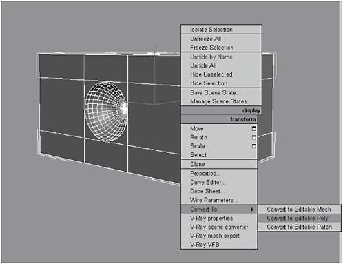
Figure 3-894
20. Unhide the Hips so you have them as a frame of reference. Select the edges on the front corners of the box and Chamfer them by 202. Select the two front polygons and Bevel them:


Figure 3-895

Figure 3-896

Figure 3-897
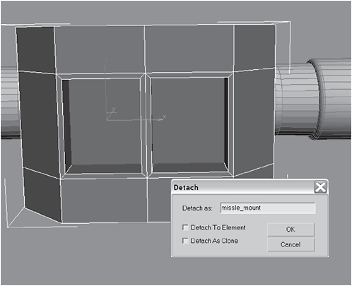
Figure 3-898

Figure 3-899
22. Create a Tube in the upper-left corner of the missle_mount and convert it to an Editable Polygon.


Figure 3-900

Figure 3-901
23. Use the Move tool and position the tube as shown below. Switch to the Front view and Shift-clone the tube in the X axis so that there is a clone in the right corner.
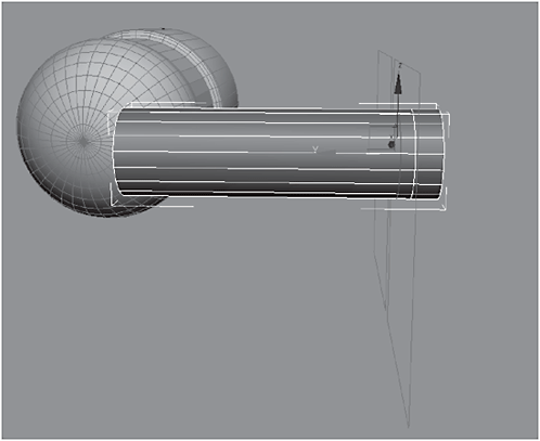
Figure 3-902

Figure 3-903
24. Select the two tubes and Shift-clone them in the Y axis to make two copies. Select the original tube and Attach the clones to it.
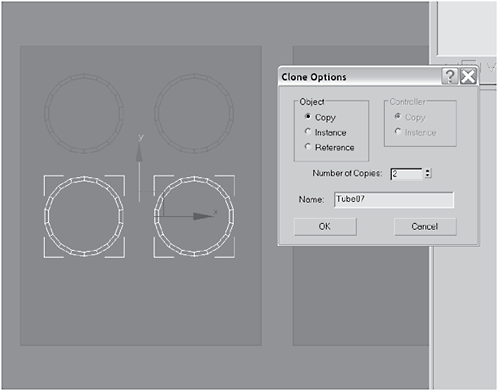
Figure 3-904

Figure 3-905

Figure 3-906
25. Select the five middle polygons on the edges of the tubes, as shown in Figure 3-907. Extrude them by 32.
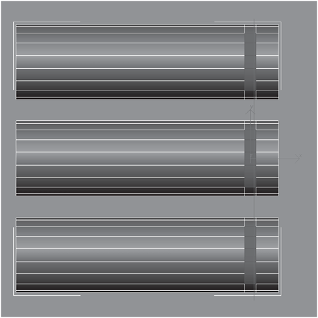
Figure 3-907

Figure 3-908
26. Scale the extrusions down to 0 in the X axis. Repeat this for the other side.
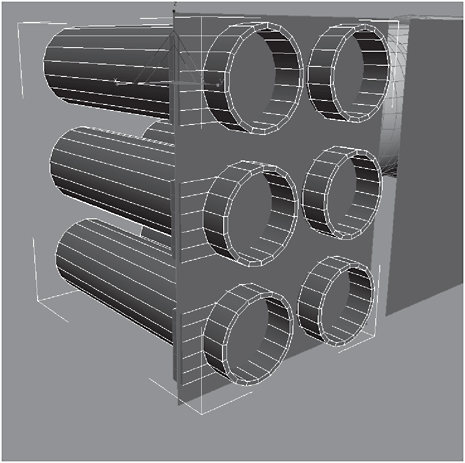
Figure 3-909
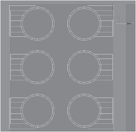
Figure 3-910
27. Select the top polygons and click the Bridge button to bridge them.

Figure 3-911
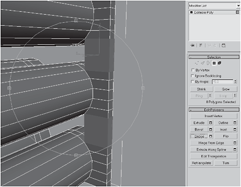
Figure 3-912
28. Bridge the polygons across the front. When you get to the last tube, the Bridge operation may try to twist on you. Should this happen, adjust the Twist value until it straightens.

Figure 3-913
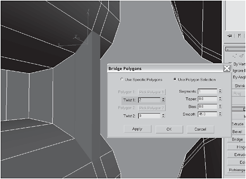
Figure 3-914
29. When you get the front completed, you’ll also need to Extrude polygons (~22.08) on the top and bottom to match the template you made by detaching the polygons (missle_mount). Use the Non-uniform Scale tool to flatten them and use the Move tool to make them flush with the template.

Figure 3-915
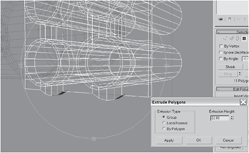
Figure 3-916

Figure 3-917
30. Clone the missile mounts you made with the extrusions and the tubes, move it to the left, and superimpose it on the missle_mount template. Hit the H key and select missle_mount. Delete it, since you don’t need it anymore.

Figure 3-918
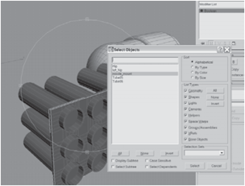
Figure 3-919
31. Select the body, click Attach List, and attach the two tubes (missile tubes made with extrusions) to the body. Use loop-select to select the bottom edges of the body.

Figure 3-920
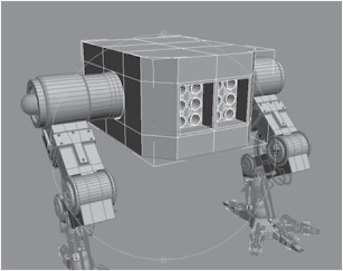
Figure 3-921
32. Right-click on the Move tool icon to open the Move Transform Type-In dialog. Set the Offset World Z axis to 121 (to raise the bottom edge, lowering the overall profile of the body). Switch to the Left viewport, click Slice Plane, and position the Slice Plane as shown in Figure 3-923. Click Slice.

Figure 3-922
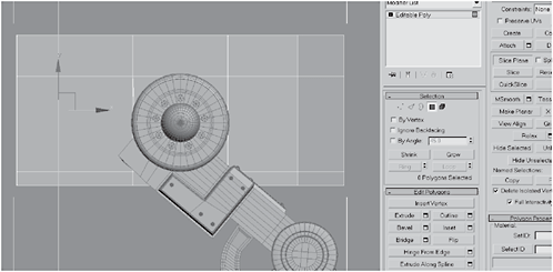
Figure 3-923
33. Target Weld the rear corners to chamfer the rear end. Activate the Slice Plane and switch to the Left viewport, then Rotate the slice plane and position it as shown in Figure 3-925, with the slice plane overlaying the bottom vertex you made with the previous slice plane. Click Slice.

Figure 3-924
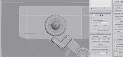
Figure 3-925
34. Select the bottom rear polygons and Target Weld the remaining segment. Select the two bottom rear segments and Bridge them.
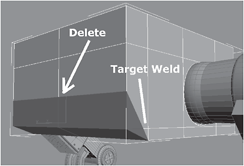
Figure 3-926
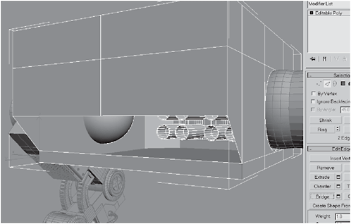
Figure 3-927
35. Border-select the remaining hole and cap it. Click Snap Settings and set the snaps to Vertex.

Figure 3-928
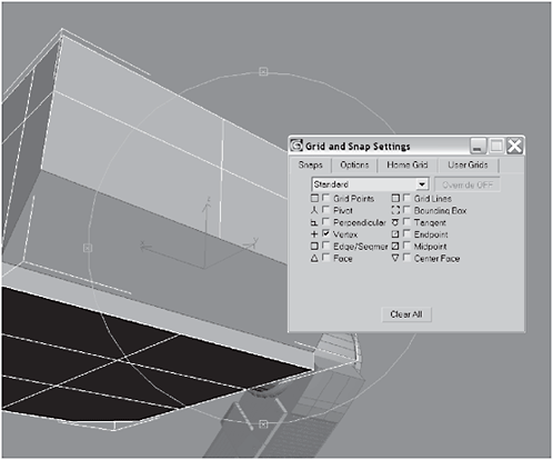
Figure 3-929
36. Use the Cut tools to cut the polygons as shown in Figure 3-930 (the Snap setting should snap the tool to the vertices, making cutting the polys easier). Select the two upper polygons from the four made from the cut and Bevel them.
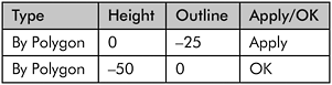
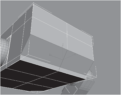
Figure 3-930
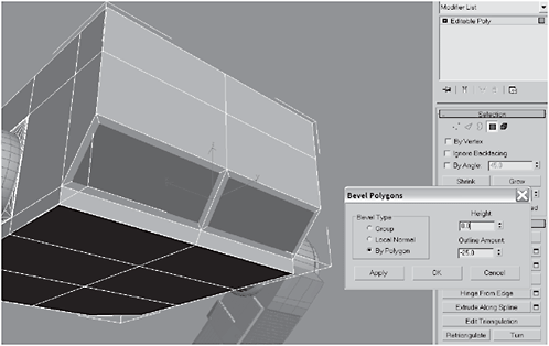
Figure 3-931
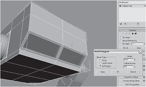
Figure 3-932
37. Select the four vertical edges, click Connect, and set the Segments to 5. With the edges still selected, Extrude them by –70 with a Base Width of 9.
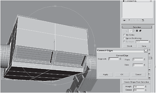
Figure 3-933
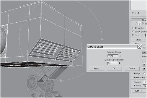
Figure 3-934
38. Select the polygons shown in Figure 3-935, on both sides, and Bevel them:
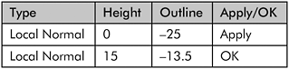
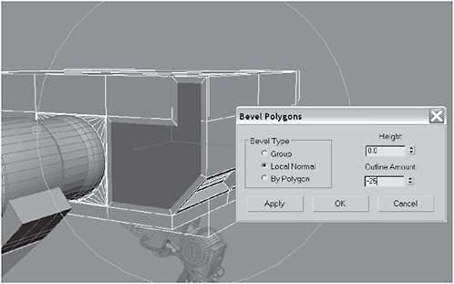
Figure 3-935

Figure 3-936
39. Select the remaining polygons, on both sides, and Bevel them:
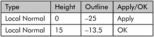

Figure 3-937

Figure 3-938
40. Select the two front panels as shown in Figure 3-939 and Bevel them:

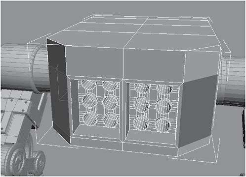
Figure 3-939

Figure 3-940

Figure 3-941
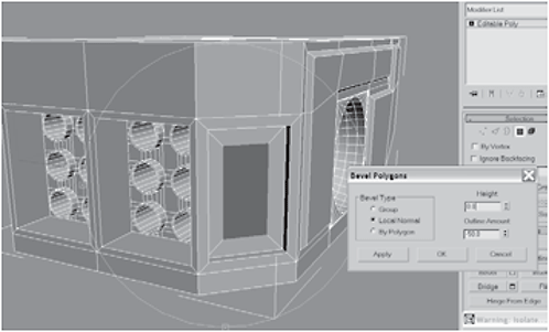
Figure 3-942

Figure 3-943
41. Create a Cylinder using AutoGrid in the upper-left corner of the indentation. Extrude it by 5 10 times.


Figure 3-944
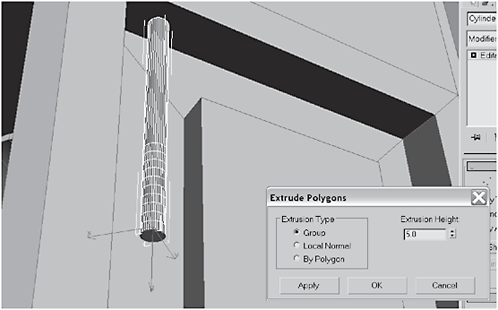
Figure 3-945
42. Clone the cylinder five times and move one of the clones to the upper-right corner. (We may not use all the clones, but keep them nearby for a while.) Move the pivot of the original to the segment at the start of the 10 extrusions.
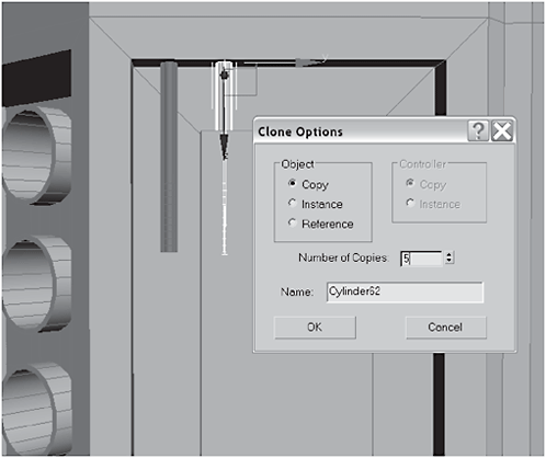
Figure 3-946

Figure 3-947
43. Select the original cylinder, add a Bend modifier to its stack with the Angle set to 90, Direction to 222.5, Z for the Bend Axis, Limit Effect checked, and Upper Limit set to 30, and convert it to an Editable Polygon. Select the top polygon and lower it in the Z axis until it’s beneath the bent cylinder.
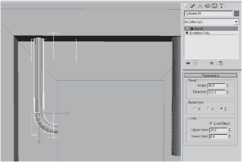
Figure 3-948

Figure 3-949
44. Select the cap of the bent cylinder and pull it in the Z axis until it’s a quarter of the way across the surface of the rectangle beneath it. Add a Smooth modifier to its stack and convert it to an Editable Polygon to collapse the stack.

Figure 3-950

Figure 3-951
45. Select and Clone the bent cylinder two times. Move the clones until they’re positioned as shown in Figure 3-953.

Figure 3-952
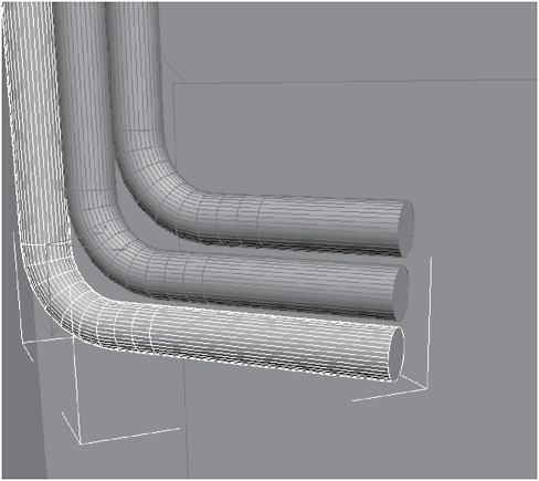
Figure 3-953
46. Create a Box at the end of the three cylinders. Convert the box to an Editable Polygon, select the two outer polygons on the bottom, and Bevel them.
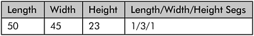

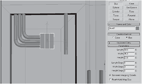
Figure 3-954

Figure 3-955

Figure 3-956
47. Select the polygon on the bottom of the straight cylinder and drag it down until it just penetrates the bottom of the box. Object-select the straight cylinder and make two clones and line them all up in the corner. Create a Box at the end of the two rectangular extrusions and convert it to an Editable Polygon.
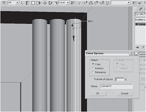
Figure 3-957

Figure 3-958
48. Select the top two polygons and Extrude them by 10. Bevel the polygons:

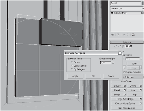
Figure 3-959
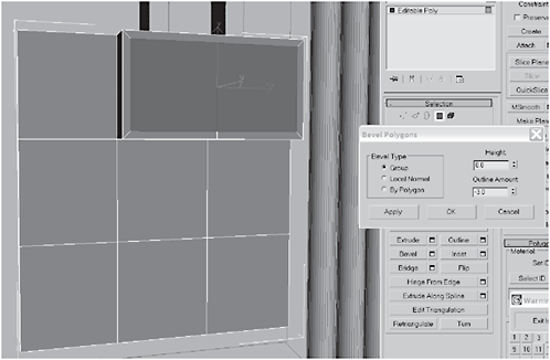
Figure 3-960
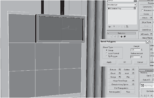
Figure 3-961
49. Select the three vertical segments and Connect the edges with 5 Segments. Extrude the edges to 6 with a Base Width of 2.25.

Figure 3-962
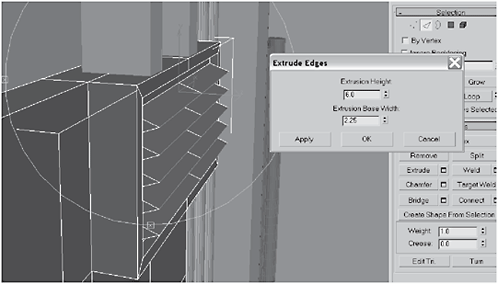
Figure 3-963
50. Push the edges down in the Y axis so they’re not sticking straight out. Create a Tube beneath the vents you just made.

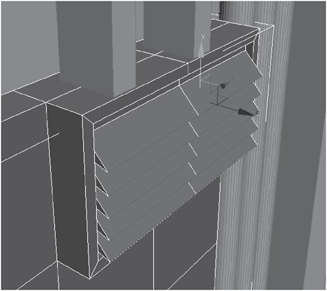
Figure 3-964
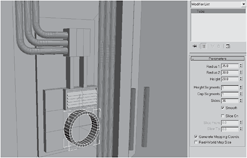
Figure 3-965
51. Create a Tube inside the tube you just made. Select every other polygon on the middle ring on the outside of the inner tube.
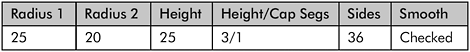
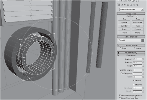
Figure 3-966
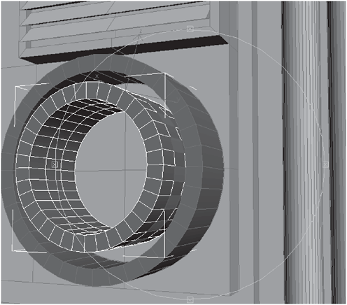
Figure 3-967
52. Extrude the polygons by 8.775, so they form spokes. Take one of the cylinder clones you made in step 42 and Rotate it 90 degrees, then move it into the the middle tube and position it near the top. Center the cylinder’s pivot point at the center of the middle tube.

Figure 3-968
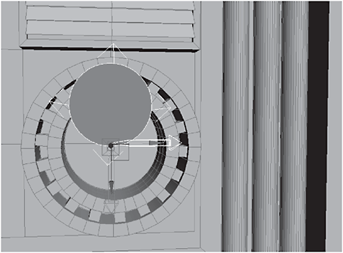
Figure 3-969
53. Uniform Scale the cylinder to 75. Hold down the Shift key and Rotate –40 degrees in the Z axis, then make eight clones. (Remember that Angle Snap will help limit the rotation to five-degree increments.)
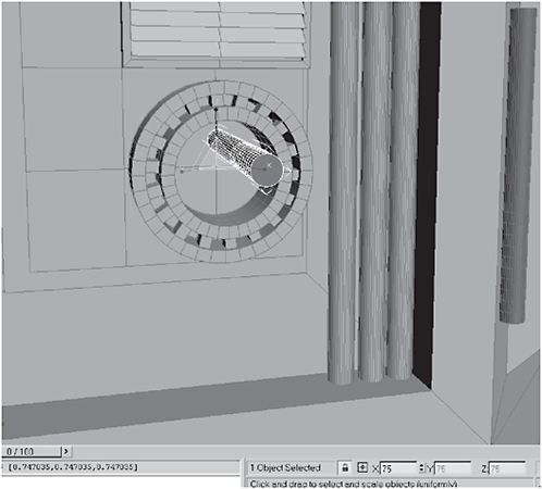
Figure 3-970

Figure 3-971
54. Using AutoGrid, create a Capsule in the upper-left missile tube on the right side of the body. Clone the capsule five times and place one in each of the tubes on the right side only.

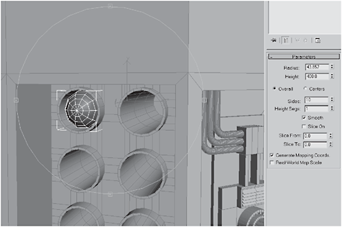
Figure 3-972
Figure 3-973
55. Select the body, click Attach List, and select everything on the body and Attach them. Marquee-select the side without missiles in the tubes and delete it.

Figure 3-974

Figure 3-975
56. Select the body, add a Symmetry modifier to the stack, and click the little test tube to show it in the viewport. Open the Editable Polygon rollout in the stack, and polygon-select the front two upper polygons (you only need to select on one side because the Symmetry modifier will select the polys for you on the other). Bevel them:

Figure 3-976
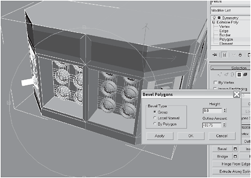
Figure 3-977
57. Create the two horizontal cuts shown in Figure 3-978. Select the edges shown in Figure 3-979, and Remove them. This will create two uninterrupted horizontal edges across the front of the body.
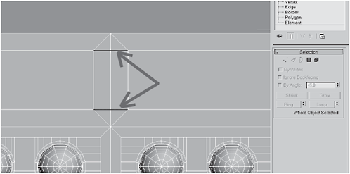
Figure 3-978
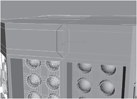
Figure 3-979
58. Select the top two polygons made from the bevel and Extrude them by –50. Look on the inside upper and lower ledges created by the extrusion. You’ll see some edges there that we don’t want. Select and Remove them.
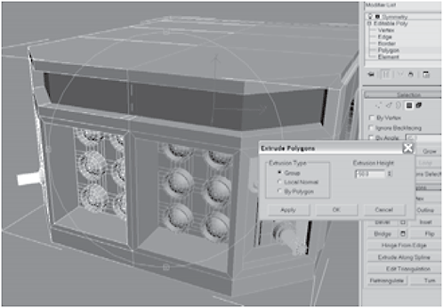
Figure 3-980

Figure 3-981
 Don’t Forget: Remove may ’ve removed the edges, but it left behind some isolated vertices. Don’t forget to remove those too or you may end up with nasty surprises in your geometry later!
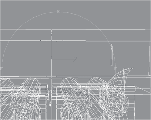
Figure 3-982
59. Be sure Weld Edges is checked under the Symmetry modifier options and then convert the Hip to an Editable Polygon to collapse the stack, merging the two halves together. Select the upper and lower edges on the inside of the recess.
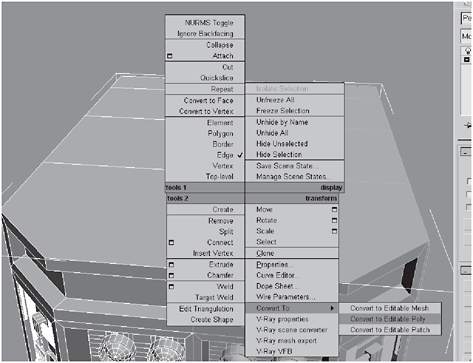
Figure 3-983
Figure 3-984
FYI: You might be wondering why we didn’t keep the Symmetry modifier around for longer. But consider all the pipes and greebles we didn’t have to make on the other side. And since we won’t be animating the missiles, we didn’t have to fully model them; just the fronts. Speaking of pipes, you should have some extras lying around. You can either delete them or hide them and use them later, as we will be making more pipes. Personally, I’d just hide them and save myself some work.
60. Connect the inner edges with 10 Segments. Extrude the edges to a Height of 42 with a Base Width of 29.788 to make vents.
Figure 3-985

Figure 3-986
61. There are some big gaps in our vents that we could spend a lot of time correcting, or … we could add some interesting widgets. Zoom into the right corner, make a Cylinder, and Bevel it:
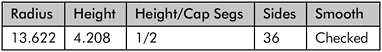


Figure 3-987

Figure 3-988

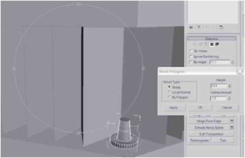
Figure 3-989
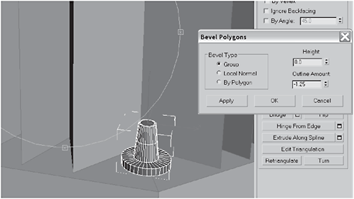
Figure 3-990
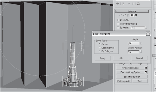
Figure 3-991
62. Select every other row of polygons on the extrusions and Bevel them By Polygon:

Figure 3-992
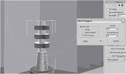
Figure 3-993
63. Select the top polygon and delete it. Object-select it and Mirror-clone it in the Z axis, with an Offset of 116,then name it shield_ emitter.
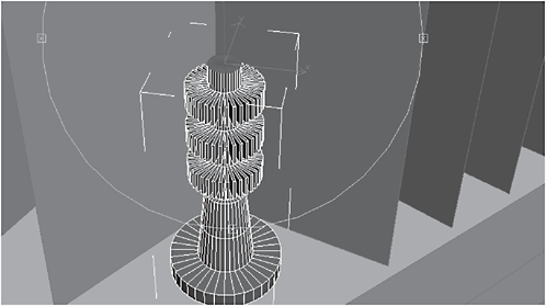
Figure 3-994
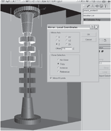
Figure 3-995
64. Attach the two parts together and Weld the center vertices.
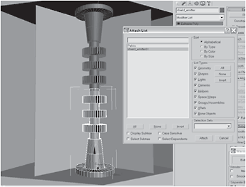
Figure 3-996

Figure 3-997
65. Shift-drag the shield_emitter in the X axis to make two clones, and place one in the center gap in the grill and one in the far left corner. Select the body, click Attach List, and attach the shield_emitters to the body.
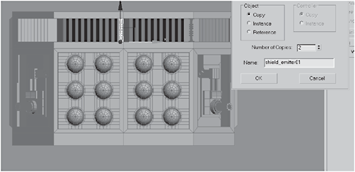
Figure 3-998

Figure 3-999
Day 9: Detailing the Rear Base and Adding the Turret and Upper Body
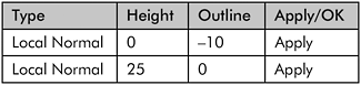
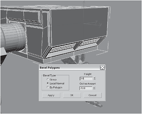
Figure 3-1000
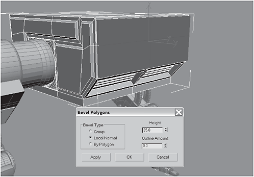
Figure 3-1001


Figure 3-1002

Figure 3-1003

Figure 3-1004


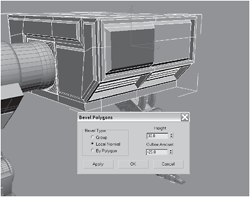
Figure 3-1005
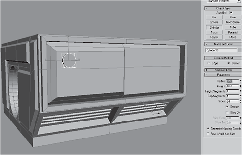
Figure 3-1006
3. Convert the cylinder to an Editable Polygon. Select the cylinder cap.
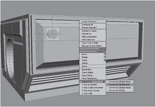
Figure 3-1007
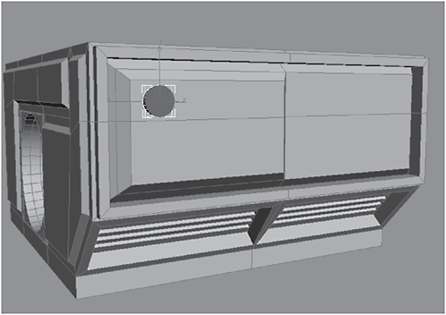
Figure 3-1008

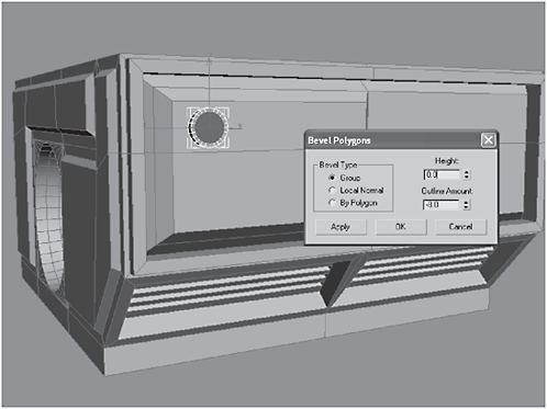
Figure 3-1009

Figure 3-1010
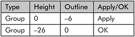
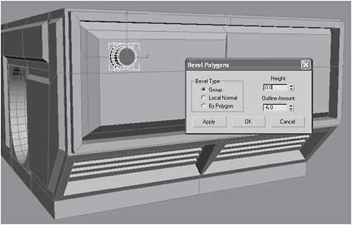
Figure 3-1011

Figure 3-1012
5. Object-select the cylinder and Shift-drag it in the Z axis to make two clones, then position them as shown in Figure 3-1014.

Figure 3-1013
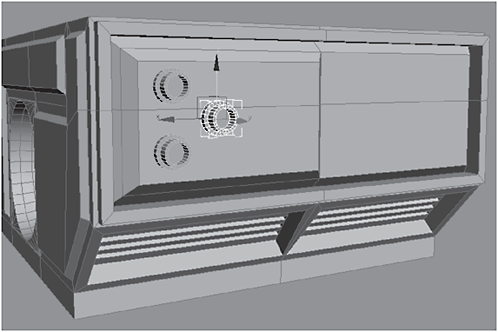
Figure 3-1014
6. Make another clone and move it to the far side of the rear, as shown. Select the body and Attach the cylinders.
Figure 3-1015
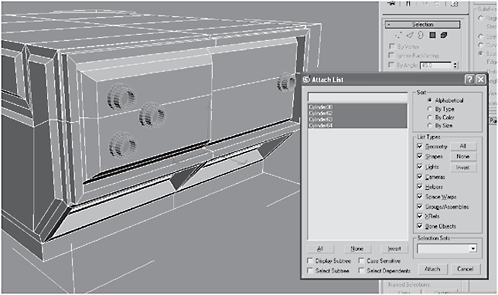
Figure 3-1016
7. Create a Line Spline from the nozzle on the right to one on the far side, as shown in Figure 3-1017. (Be sure to select each vertex, right-click, and make it Smooth so you get a curving hose.) Create a three-point Spline traveling from the topmost nozzle to the first spline.
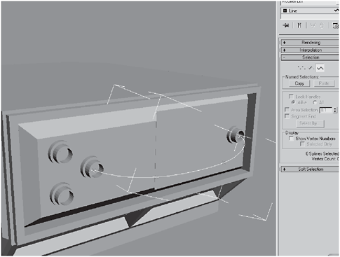
Figure 3-1017
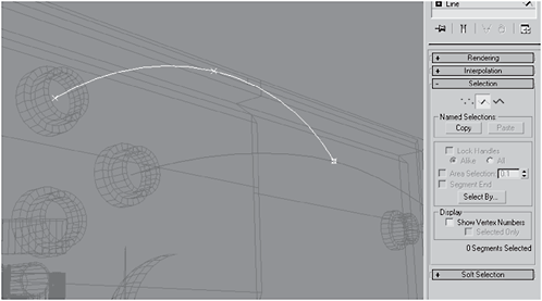
Figure 3-1018
Fire Drill: This is a workaround, because, to the best of my knowledge, there is no graceful way to make a hose that splits, like one you might find on a manifold or a distributor. If someone knows a better way to do this, please email me; I’ve been looking for a better way for a while. The way I’m going to show you works, but the results are not very satisfying. You could create multiple polygonal cylinders, add Bend modifiers to them, and then connect them using Bridge to merge the polygons or edges, but I can’t imagine that approach’s results would be sufficiently better to justify the extra work. This approach is, at least, pretty simple.
8. Create another three-point Spline from the vertex where the last spline intersected with the original to the bottom nozzle.

Figure 3-1019
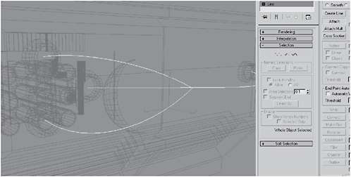
Figure 3-1020
9. Attach the ancillary splines to the original, then select the three intersecting vertices and click Weld. Under Rendering, select Enable In Renderer and Enable In Viewport. Click Radial, and set the Thickness to around 45 (mine was 45.11) and the Sides to 16.

Figure 3-1021
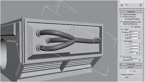
Figure 3-1022
10. Convert the line to an Editable Polygon (or Patch or NURBS).
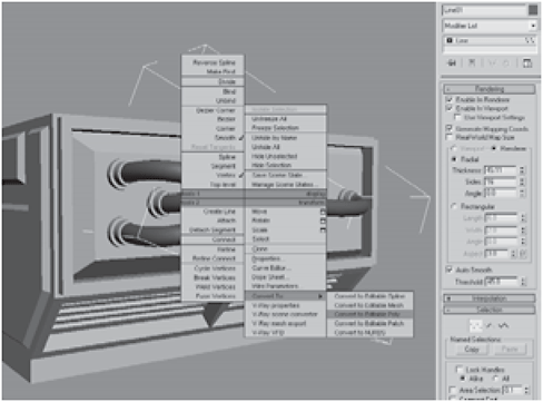
Figure 3-1023

Figure 3-1024
11. In the recessed part of the rear, select the top, middle, and bottom edges and Connect them with 1 Segment. Chamfer the new edge by 80 to create two edges.
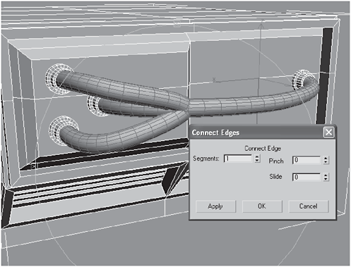
Figure 3-1025

Figure 3-1026
12. Select the far left vertical edges and move them to the left in the X axis, as shown. Exact values are not important; just eyeball it. Select the polygons between the edges you made with the Chamfer.

Figure 3-1027

Figure 3-1028
13. Just to be different, select the outer polygons and Bevel them:
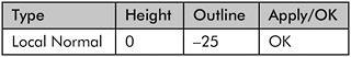
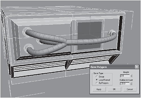
Figure 3-1029

Figure 3-1030
14. Extrude the polygons by 10. Select the top, middle, and bottom edges. (Yes, we’re about to make more vents!)
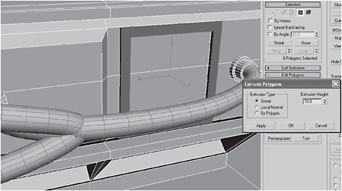
Figure 3-1031
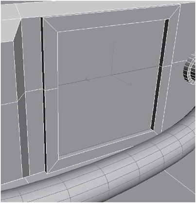
Figure 3-1032
15. Connect the edges with 6 Segments. Extrude them by 42 with a Base Width of 30.

Figure 3-1033

Figure 3-1034
16. Create a Torus, center it atop the base, and submerge it halfway into the base. Create a Cylinder in the center of the torus.
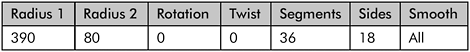
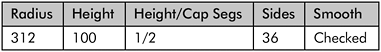

Figure 3-1035
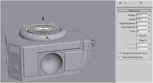
Figure 3-1036
17. Convert the cylinder to an Editable Polygon, select the inner cap segments, and Scale them up to 130. Select the inner 36 polygons and six of the outer polygons to form a keyhole shape.
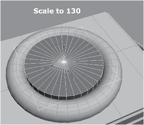
Figure 3-1037

Figure 3-1038
18. Extrude the polygons by 200. Create a Tube over the top of the extrusion:


Figure 3-1039
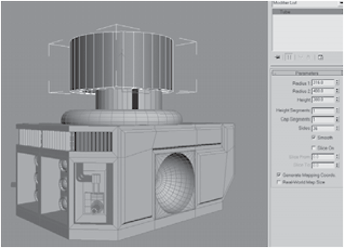
Figure 3-1040

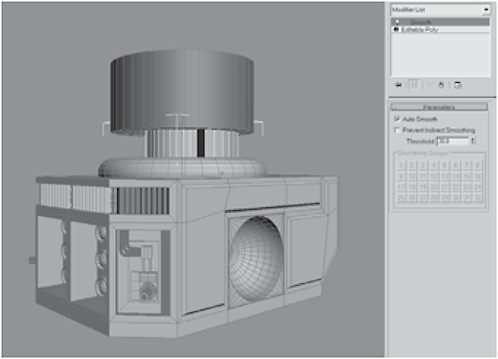
Figure 3-1041
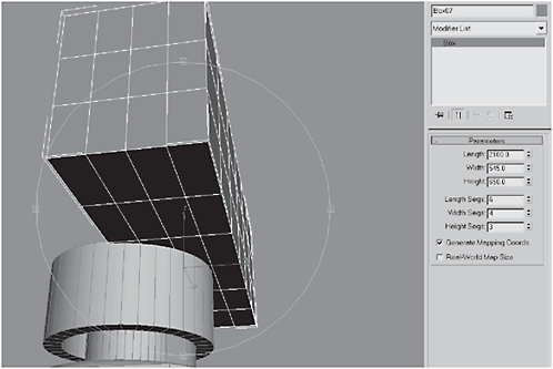
Figure 3-1042
20. Convert the box to an Editable Polygon. Select the polygons facing the center and delete them. Add a Symmetry modifier to the box’s stack with the Mirror Axis set to X.
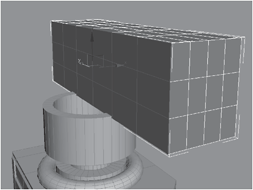
Figure 3-1043

Figure 3-1044
21. Select the four bottom-facing polygons on the front of the box, and Extrude them by 300 to form a lip that extends down from the front. Select the edges forming the front corner and Chamfer them by 62.
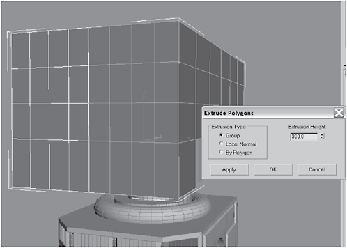
Figure 3-1045
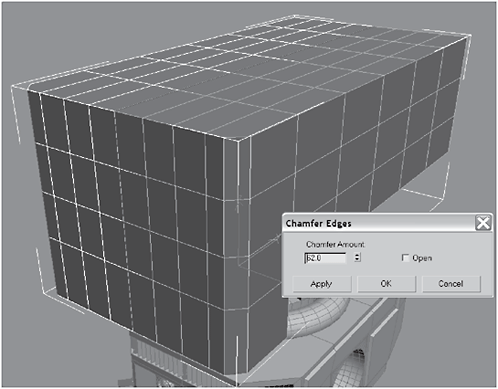
Figure 3-1046
22. Select the back four polygons on the top side and top surface of the box, and Extrude them by 475. Select the middle four polygons on the extrusion you made.

Figure 3-1047

Figure 3-1048
23. Delete the selected polygons. Select the resulting four edges, as shown in Figure 3-1050.
Figure 3-1049
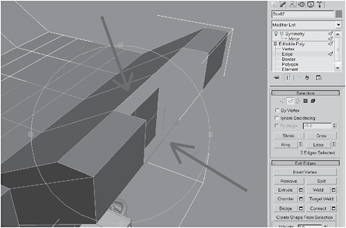
Figure 3-1050
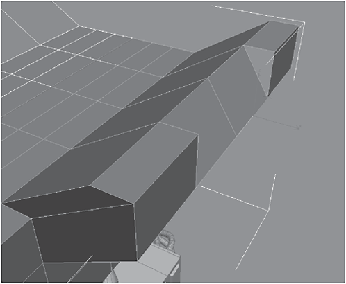
Figure 3-1051
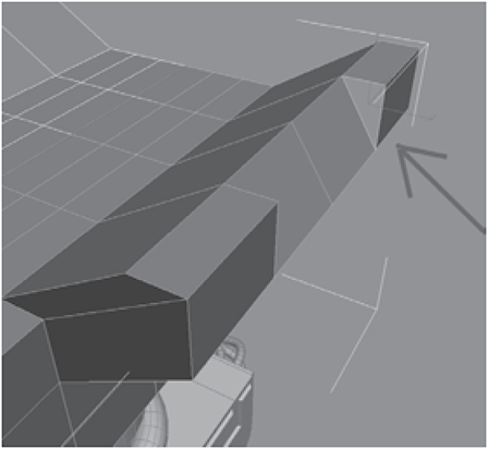
Figure 3-1052
25. Connect the three vertical edges with 1 Segment. Select the bottom front and rear polygons on the extrusion and Extrude them by 350.

Figure 3-1053

Figure 3-1054
26. Select the front polygon and Shift-drag it to clone it to element, then move it in the Y axis until the left edge of the polygon coincides with the middle segment in the recess. Hinge From Edge 180 degrees with 10 Segments, using the left edge of the cloned element. Delete the back-facing polygon and Weld the resulting vertices.
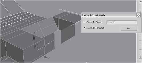
Figure 3-1055
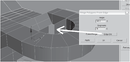
Figure 3-1056


Figure 3-1057
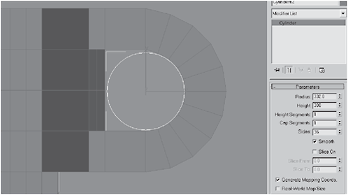
Figure 3-1058
28. Vertically center the cylinder in the hole. Reduce the cylinder’s Height to 280 and Instance Mirror a clone of it on the X axis into the hole on the opposite side of the body (Offset should be around –2575.5).

Figure 3-1059
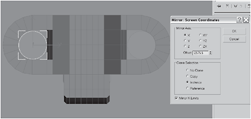
Figure 3-1060
29. Select the cylinders’ caps and Bevel them (since it’s an instance copy, you do not have to repeat for the opposite side):

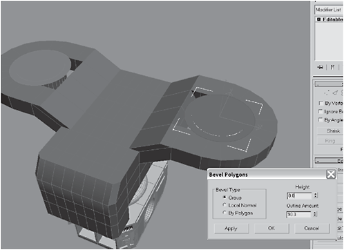
Figure 3-1061

Figure 3-1062

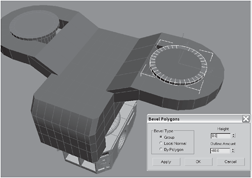
Figure 3-1063

Figure 3-1064
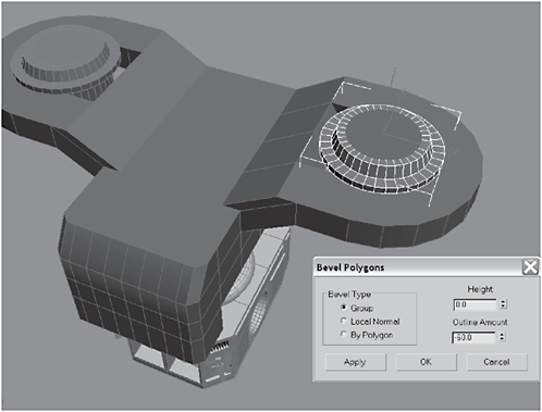
Figure 3-1065
30. Cut the cylinder cap as shown in Figure 3-1066, then select the four edges and Connect them with 1 Segment.
Figure 3-1066
Figure 3-1067
31. Chamfer the new edge by 108 to make two edges. Select the resulting polygons and Extrude them by 20 to form an H.
Figure 3-1068
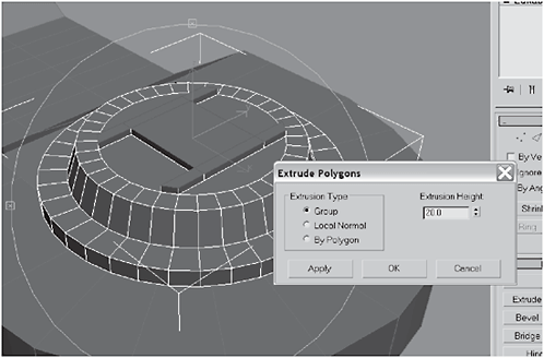
Figure 3-1069
32. Select the polygons that form the vertical parts of the H and Extrude them by 40.

Figure 3-1070
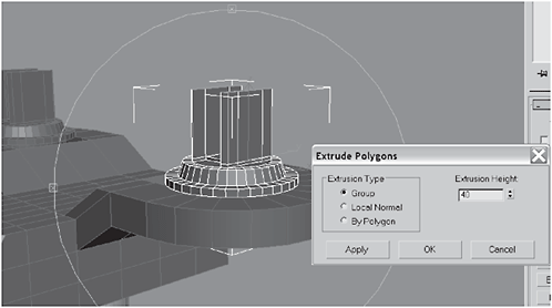
Figure 3-1071
33. Select the front eight vertices and move them by 120 in the Y axis. Create a Chamfer Box between the vertical sides of the fork.

Figure 3-1072

Figure 3-1073
34. Target Weld the front four vertices of each side of the fork to make it look raked.
Figure 3-1074

Figure 3-1075
35. Select the tops of the mounts, Extrude them by 140, and Scale them down to 50 in the Y axis.

Figure 3-1076
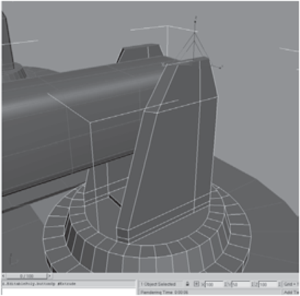
Figure 3-1077
36. Create a Chamfer Cylinder and convert it to an Editable Polygon. Select the center cap, position it as shown in Figure 3-1078, and Extrude it by 10.


Figure 3-1078

Figure 3-1079
37. Select the center of the cylinder and Bevel it. Add a TurboSmooth modifier to the stack and leave all the settings on their defaults. Hide the chamfer box to give yourself some space.

Figure 3-1080

Figure 3-1081
38. Mirror-copy the chamfer cylinder to the other side of the brace. Select the two chamfer cylinders you’ve already made and clone to the opposite side.
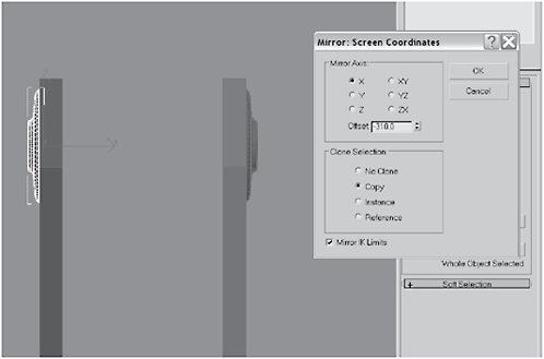
Figure 3-1082

Figure 3-1083
39. Select all the top objects (e.g., body, braces, gun turrets, etc.) and Scale them down to 88 to balance the top with the size of the base.
Figure 3-1084

Figure 3-1085
40. Select the gun turret and Attach the chamfer cylinders to it. Unhide the chamfer box and convert it to an Editable Polygon.
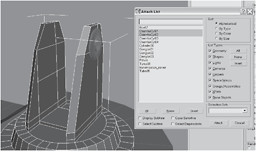
Figure 3-1086

Figure 3-1087


Figure 3-1088

Figure 3-1089
42. Click MSmooth and leave the default setting of 1.0. Extrude the polygons by –70.

Figure 3-1090

Figure 3-1091
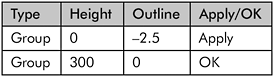
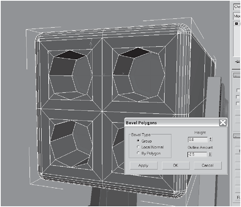
Figure 3-1092
Figure 3-1093
44. Extrude the polygons by Local Normal by 400, and then Bevel them:

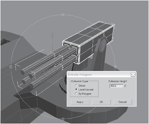
Figure 3-1094
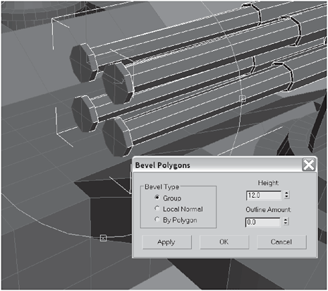
Figure 3-1095

Figure 3-1096

Figure 3-1097
45. Switch to the Front viewport, open the Spline panel, and create a Helix around the barrel you created with the bevels and extrusion:
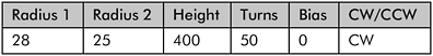

Figure 3-1098
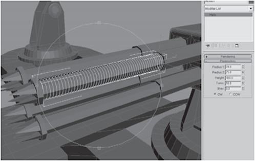
Figure 3-1099
46. Click Enable In Viewport and Enable In Renderer, and set the Thickness to 1.5 and the Sides to 12. In the Top view, Shift-clone the helix, in the X axis, over to the other barrel. Select both helixes, switch to the front, and Shift-clone down to the bottom two barrels.
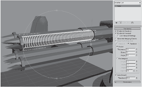
Figure 3-1100
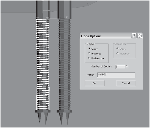
Figure 3-1101
47. Select the edges on the chamfer box as shown in Figure 3-1102 and then Extrude them by a Height of –1.0 with a Base Width of 0.75 to create machine lines on the gun body.

Figure 3-1102
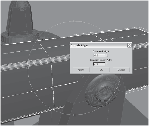
Figure 3-1103
48. Select the front polygons bounded by the machine lines and Bevel them:

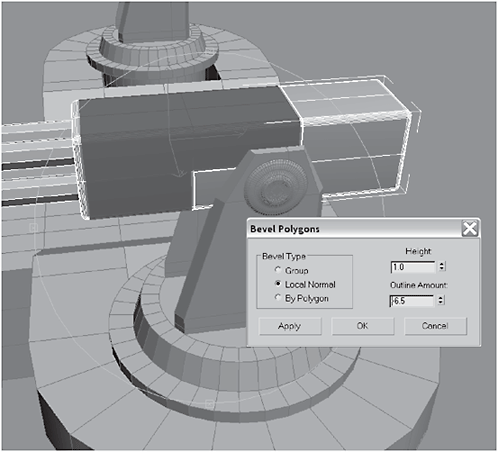
Figure 3-1104
49. Select the top front polygons and Bevel them:


Figure 3-1105
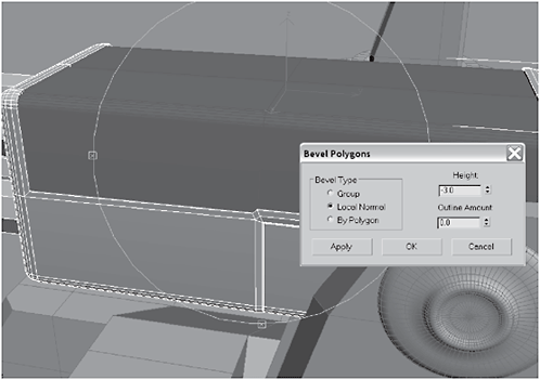
Figure 3-1106
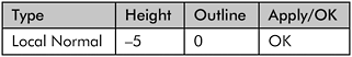
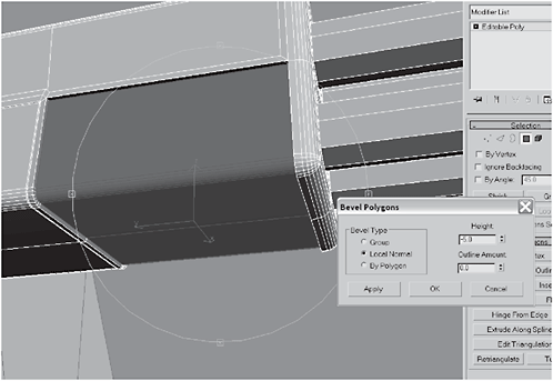
Figure 3-1107
51. Select the horizontal segments in the area you just beveled inward, Connect them with 1 Segment, and then Chamfer the edge by 45 and hit Apply (not OK).
Figure 3-1108

Figure 3-1109

Figure 3-1110
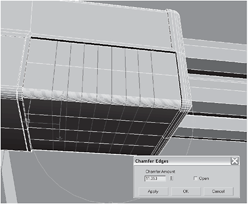
Figure 3-1111
53. Extrude the edges by –2 with a Base Width of 1. Select the top two middle polygons and Bevel them:

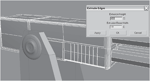
Figure 3-1112
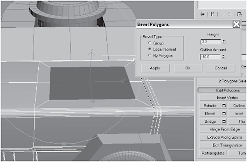
Figure 3-1113
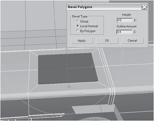
Figure 3-1114
54. Select the polygon indicated in Figure 3-1115 and click Tessellate. Select the opposite polygon and Bevel it:
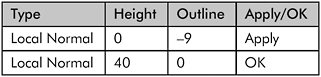

Figure 3-1115
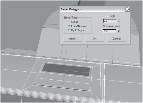
Figure 3-1116
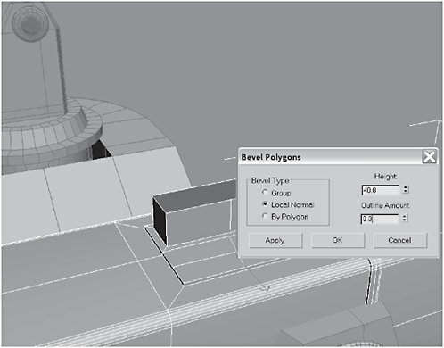
Figure 3-1117
55. Select the bottom set of polygons in the form of an L, as shown, and Bevel them:
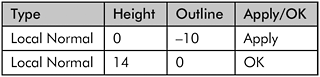

Figure 3-1118
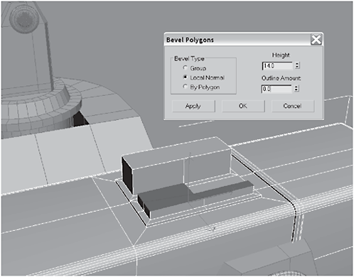
Figure 3-1119

Figure 3-1120
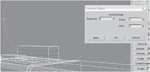
Figure 3-1121
57. Select the rear middle polygon and Extrude it by Local Normal 12. Non-uniform Scale the polygon down to 70 in the Y axis.
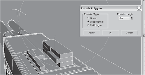
Figure 3-1122
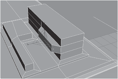
Figure 3-1123
58. Hinge From Edge an Angle of 90 degrees with 10 Segments, click Pick Hinge, and click the bottom edge. Bevel them:
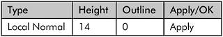

Figure 3-1124
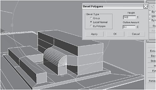
Figure 3-1125
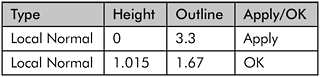

Figure 3-1126

Figure 3-1127
59. Create a Tube on top of the L shape and create a clone of that tube.
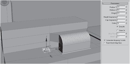
Figure 3-1128

Figure 3-1129
60. Rotate the cloned tube 90 degrees in the Y axis. Move the tubes so the edges are just below the surfaces.
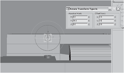
Figure 3-1130
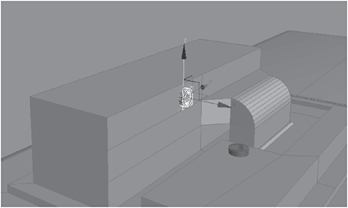
Figure 3-1131
Figure 3-1132

Figure 3-1133
62. Select the center vertex, right-click, and choose Smooth. Adda Sweep modifier to the spline’s stack, choose Use Built-In Section, and pick Cylinder from the drop-down.

Figure 3-1134
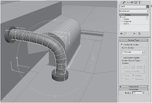
Figure 3-1135

Figure 3-1136
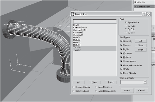
Figure 3-1137
64. Select the top two polygons on the vertical part of the box and Bevel them inward:
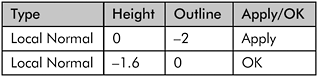
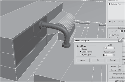
Figure 3-1138

Figure 3-1139
65. Select the tube and Shift-clone in the Y axis, making four copies. Select the body and Attach the tubes (shown as Lines in the list, because they’re based on splines).
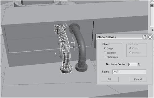
Figure 3-1140
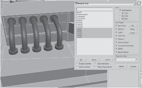
Figure 3-1141

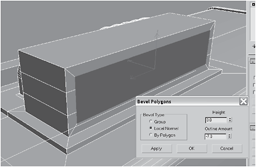
Figure 3-1142

Figure 3-1143
67. Create a Gengon and convert it to an Editable Polygon, then select the back-facing polygons and delete them.
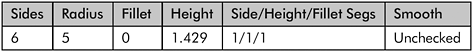
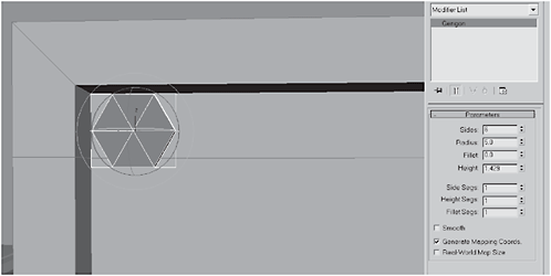
Figure 3-1144

Figure 3-1145


Figure 3-1146

Figure 3-1147
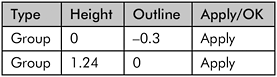
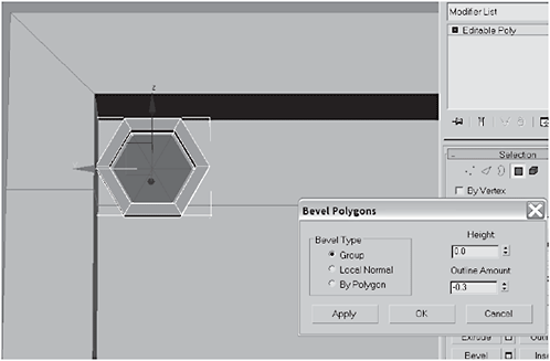
Figure 3-1148
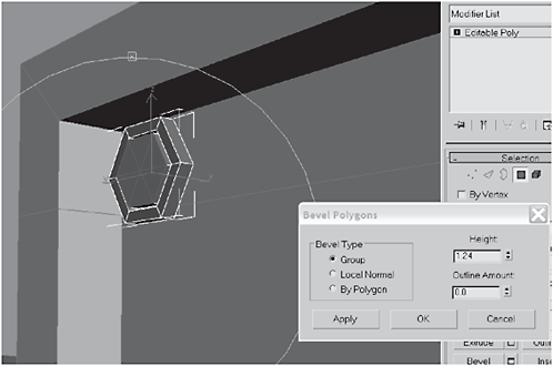
Figure 3-1149


Figure 3-1150
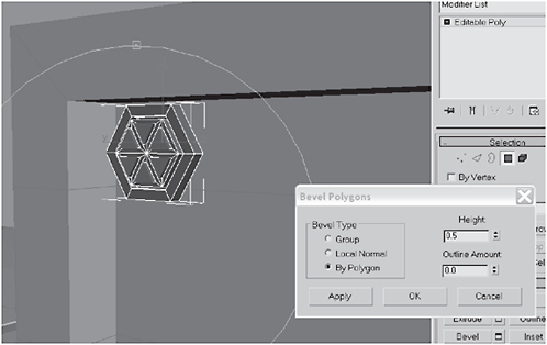
Figure 3-1151
69. Clone the gengon enough times to fill the box and arrange them as shown in Figure 3-1153, then select the body and Attach the gengons to the body.
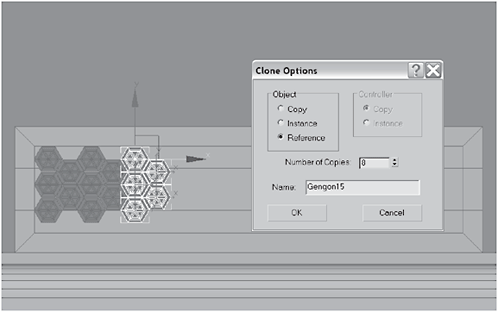
Figure 3-1152

Figure 3-1153
Figure 3-1154
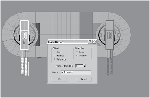
Figure 3-1155
Day 10: Detailing the Upper Body
1. Select the middle polygons of the stanchion that holds the gun mount. Bevel them and Non-uniform Scale them down to 50 in the Offset Local X axis.
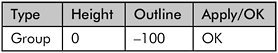

Figure 3-1156
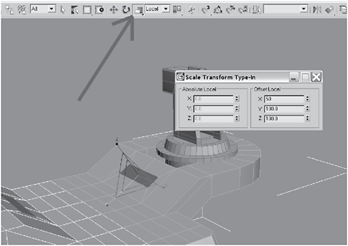
Figure 3-1157
2. Extrude the polygons by 609 (or until they meet their symmetric opposite to form a bridge shape). Select the two polygons in the middle of the three polygons beneath the extrusion you just made.

Figure 3-1158

Figure 3-1159
Figure 3-1160
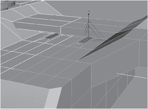
Figure 3-1161
4. Extrude the polygons 140. Right-click the Move tool and type 100 for the Offset Local X axis.
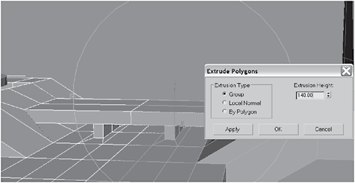
Figure 3-1162

Figure 3-1163
5. Create a Box at the rear of the bridge you just made. Convert the box to an Editable Polygon, select the top polygon made by the top height segment and facing the front, and Extrude it by 223.83 so it extends halfway across the bridge.
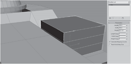
Figure 3-1164

Figure 3-1165
6. Select the top edge of the extrusion and Chamfer it by 28.Createa Cylinder at the front top corner of the extrusion over the bridge and then Clone one for the opposite side.


Figure 3-1166

Figure 3-1167
7. Select and Link the cylinders to the box and then Select and Link the box to the body. Create a Tube on top of the box and center it over the top part of the box that does not extend over the bridge.
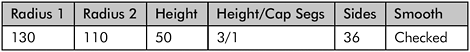
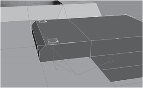
Figure 3-1168
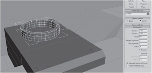
Figure 3-1169
8. Add a Lattice modifier to the tube’s stack; this will create a mesh-looking object, like an antenna tower. Add a GeoSphere to the top of the lattice tube.

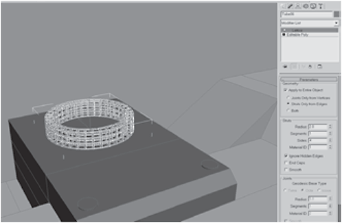
Figure 3-1170

Figure 3-1171


Figure 3-1172
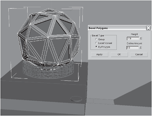
Figure 3-1173
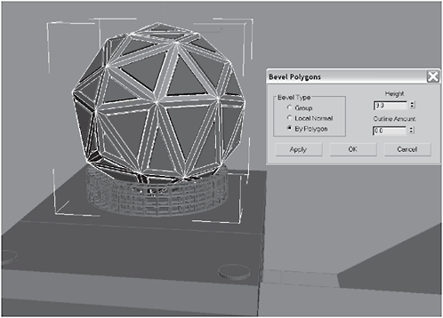
Figure 3-1174
10. Select the bottom two polygons on both sides and the middle polygon on the rear of the box, and Bevel them. Then Shift-click the Edge selection mode icon to switch from Polygon selection mode. (Note: Shift-clicking will not only switch from polygon to edge, but will select all the edges making up the polygons that are currently selected.)
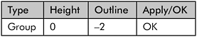
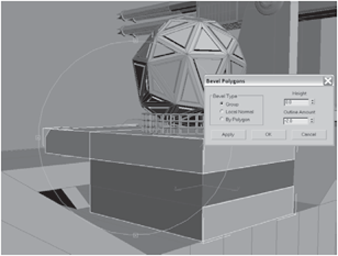
Figure 3-1175

Figure 3-1176
11. Extrude the edges by –1 with a Base Width of 3 to create deep machine lines in the box. Switch to wireframe mode and edge-select the edges shown darkened in Figure 3-1178.
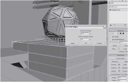
Figure 3-1177

Figure 3-1178
12. Extrude the edges by –10 with a Base Width of 3.5 to create deep machine lines in the body. Switch back and forth from wireframe to shaded as needed and select the edges shown darkened in Figure 3-1180.

Figure 3-1179

Figure 3-1180
13. Select the edges shown in Figure 3-1181 and Extrude them by –10 with a Base Width of 3.5 to create deep machine lines in the stanchions.
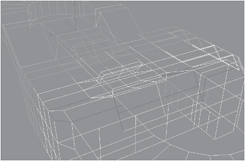
Figure 3-1181

Figure 3-1182
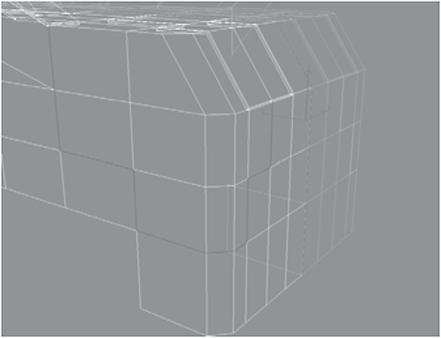
Figure 3-1183

Figure 3-1184

Figure 3-1185
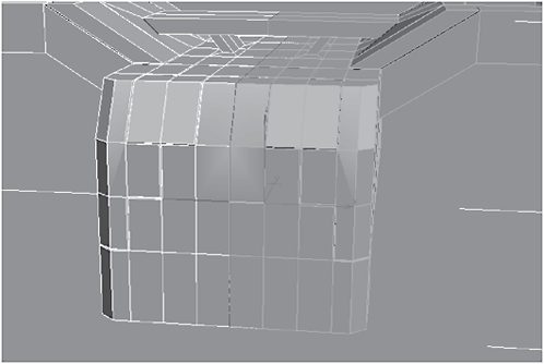
Figure 3-1186
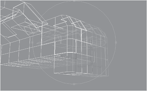
Figure 3-1187

Figure 3-1188
15. Extrude the Edges by –10 with a Base Width of 3.5. Select the bottom front six polygons and Bevel them:
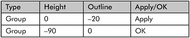

Figure 3-1189
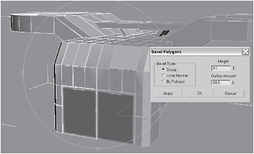
Figure 3-1190

Figure 3-1191
16. Convert the body to an Editable Polygon to fuse the two halves together. Select the polygons inside the recesses and Detach them as missle_tube template.
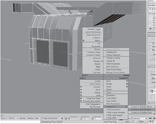
Figure 3-1192

Figure 3-1193
17. Create a Tube and convert it to an Editable Polygon. Make three clones across the top of the template, select those tubes, and make five rows of clones.

Figure 3-1194
Figure 3-1195
18. Select the original tube and Attach all the clones. Select the middle five polygons on the original and on the first clone and Bridge them. Repeat this process to create the missile tubes the same way you did for the base.

Figure 3-1196
Figure 3-1197
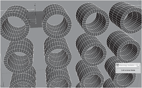
Figure 3-1198


Figure 3-1199
20. Select the caps on the undersides of the gun turrets and Bevel them:


Figure 3-1200

Figure 3-1201
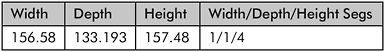
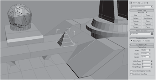
Figure 3-1202
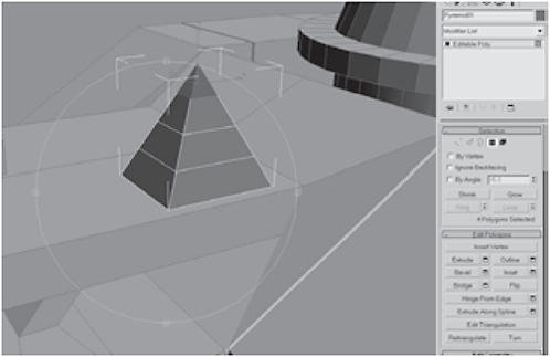
Figure 3-1203
22. Border-select the top, Cap it, and, with all the edges on the top still selected, Non-uniform Scale down to 80 in the X axis.

Figure 3-1204

Figure 3-1205
23. Select the cap and Extrude it by –1 with the type setting of Local Normal, and then click MSmooth.
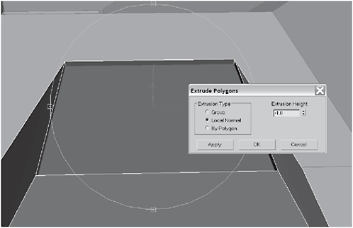
Figure 3-1206

Figure 3-1207

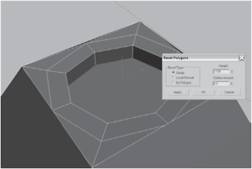
Figure 3-1208

Figure 3-1209
25. Extrude by Local Normal by 100 and hit Apply. Then Extrude by 10 and hit Apply fifteen times. This will create a strange four-panel spade shape.
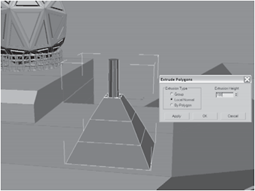
Figure 3-1210

Figure 3-1211
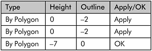
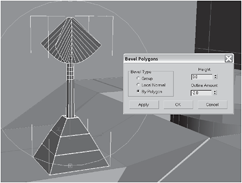
Figure 3-1212
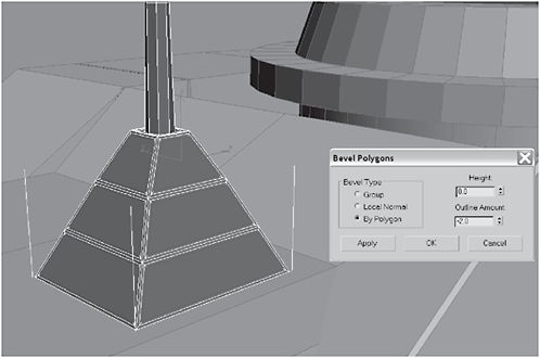
Figure 3-1213

Figure 3-1214
27. Select and Detach the top and just leave it named Object01.With Object01 still selected, add a Lattice modifier to its stack.


Figure 3-1215
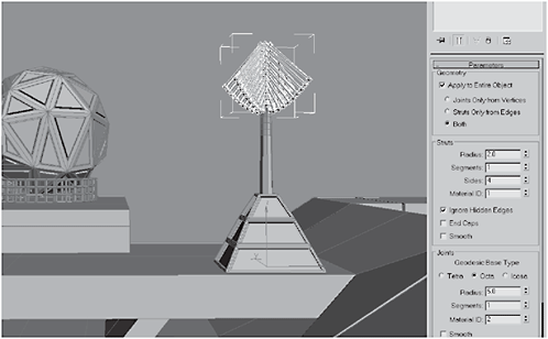
Figure 3-1216

Figure 3-1217
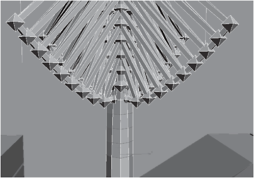
Figure 3-1218
29. Extrude the edges by 10 with a Base Width of 3. Clone the antenna assembly to the other side of the bridge.
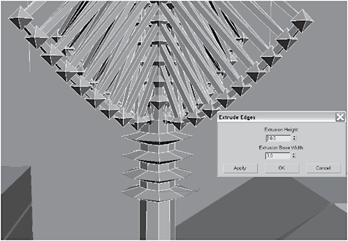
Figure 3-1219

Figure 3-1220
30. Create a Spline that meanders from the base of the pyramid to the base of the geosphere. Select every vertex on the spline, right-click, and change all of them to Smooth. Switch to the Perspective view, arc rotate, and make sure the spline drapes smoothly over the edges and beneath the lattice.
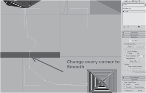
Figure 3-1221
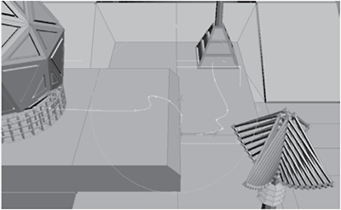
Figure 3-1222
31. Add a Loft modifier to the spline with a Thickness of 15 and 12 Sides. Choose Enable In Renderer and Enable In Viewport and then convert it to an Editable Polygon to collapse the stack. Create another Spline connecting the other antenna to the geosphere and Loft it using the same settings.
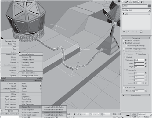
Figure 3-1223
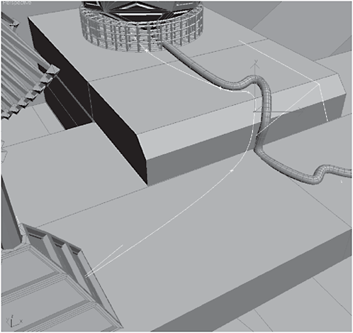
Figure 3-1224
32. Select the torso and add a Smooth modifier to its stack. Switch to the Front view and create a closed Spline object beneath a turret as shown in Figure 3-1226.

Figure 3-1225
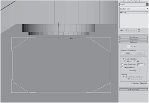
Figure 3-1226
33. Add an Edit Spline modifier to the stack and Clone the spline twice. Select the rearmost spline and Uniform Scale it down to 50 percent.
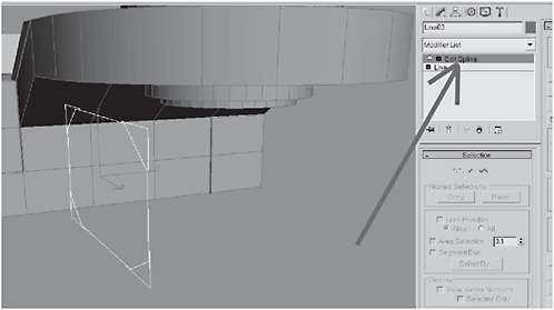
Figure 3-1227
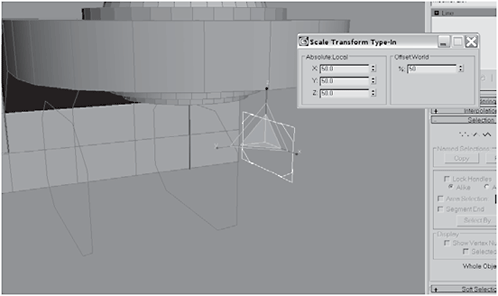
Figure 3-1228
FYI: To make the cannon nacelle, we’ll use a CrossSection modifier. The CrossSection modifier requires the Edit Spline modifier be applied, the splines arranged in sequence, and the CrossSection modifier added on top.
34. Switch to the Right viewport and raise the rear spline in the Y axis, until it is centered vertically behind the middle spline. Uniform Scale the last spline to 70.

Figure 3-1229

Figure 3-1230
35. Add a CrossSection modifier to the top of the stack. Add a Surface modifier to the top of the stack to “skin” it.
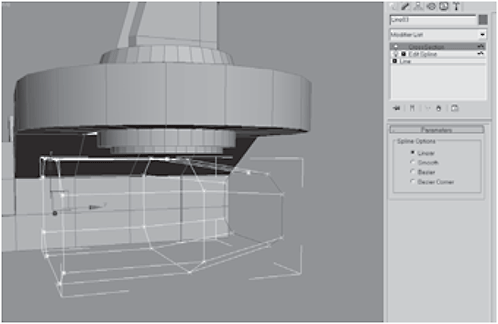
Figure 3-1231

Figure 3-1232
36. Add an Edit Poly modifier to the top of the stack so we can cap the holes. Select the borders and Cap them.
Figure 3-1233

Figure 3-1234
37. Select the caps and Bevel them:

Figure 3-1235
Figure 3-1236
38. Loop-select the two edges beneath the turret. Click Create Shape and name it cannon_stanchions. Uniform Scale the shapes up to 112 and set the Thickness to 95 with 4 Sides, and choose Enable In Viewport and Enable In Renderer. Select and Link the stanchions and nacelles to the turret.
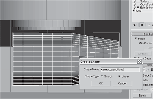
Figure 3-1237
Figure 3-1238

Figure 3-1239
Figure 3-1240
39. To add more machine lines to the smooth sides of the cannon_stanchions, select the edges shown in Figure 3-1241. Extrude them –5 with a Base Width of 1.2.
Figure 3-1241

Figure 3-1242
40. Now hide everything except the right gun turret. Switch to the Right viewport and create a Spline like the one shown below. Add a Lathe modifier to the stack, set the Direction to X, under Align click the Min button, and set the output to either NURBS or Patch. I selected NURBS because that gives you a smooth output. (Note: Patch would give you an equally smooth output. The only real difference comes in if you want to model or edit the form, but I’m not going to so it makes little difference.) Click the Lathe modifier, click Axis, and move the axis cursor down in the Y axis until the cannon is the width you want.

Figure 3-1243
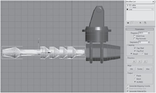
Figure 3-1244
41. Right-click the spline and choose Convert to NURBS to collapse the stack. Switch to the Front view and Clone to make a second cannon.

Figure 3-1245
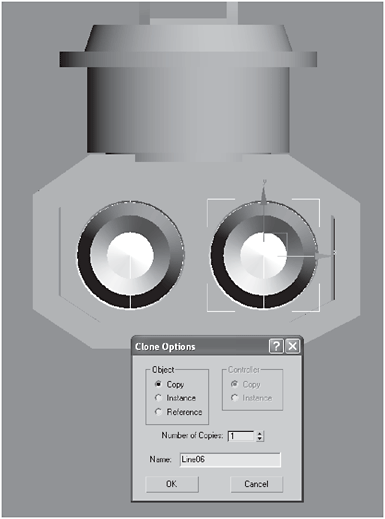
Figure 3-1246
42. Move both cannons into the nacelles. Unhide All. Select both cannons and Mirror-copy them with an Offset of –2350 (or whatever value gets them centered on the left nacelle). Select and Link the cannons to their respective nacelles.

Figure 3-1247
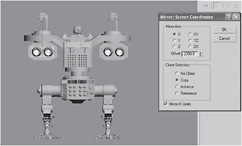
Figure 3-1248
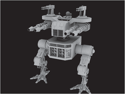
Figure 3-1249

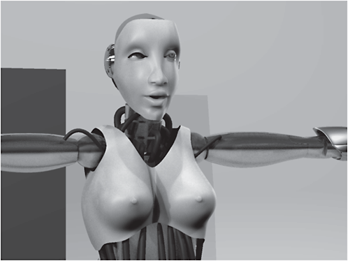
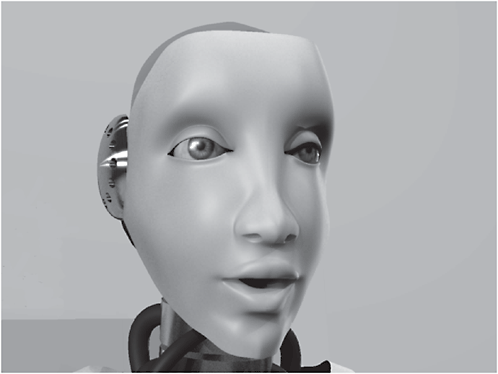
This is the android we create in Chapter 4.