
7
Two Chairs and a Vase
In this chapter, we’ll work in the Sculpt workspace and take a couple of short detours through the Patch and Mesh workspaces to make some organic-shaped chairs and a vase.
Tall-Back Chair
Click the Create Form icon to enter the Sculpt workspace and then choose Create → Box (Figure 7-1). Make a box equally sized on all axes (Figure 7-2).
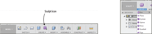
Figure 7-1: Enter the Sculpt workspace and click Box.
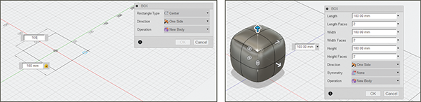
Figure 7-2: Make a box of equal proportions.
Edit Form
Select two faces on the top, as shown in Figure 7-3. Right-click, and then choose Subdivide. The two faces will turn into eight (Figure 7-4).
Figure 7-3: Subdivide the top into multiple faces.
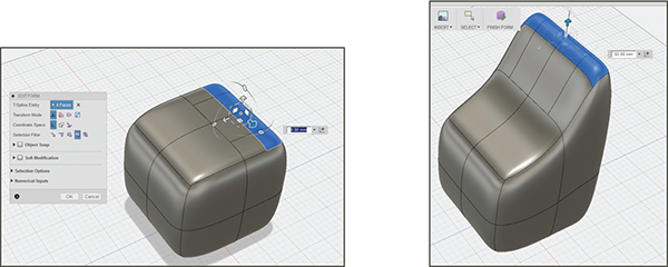
Figure 7-4: Select faces, choose Edit Form, and pull the faces up.
Select the edge faces, right-click, and choose Edit Form. A widget will appear; pull the selected faces up. Then select the seat, right-click, and choose Edit Form. Push the face down (Figure 7-5).
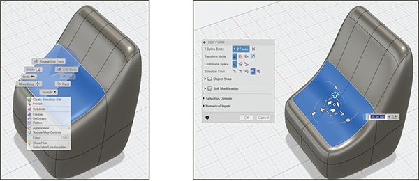
Figure 7-5: Use Edit Form to push the chair’s seat down.
Select and right-click the seat edge shown in Figure 7-6 and choose Insert Edge. Drag the handle to place the new edge below the original one and click OK. The chair’s shape will change a bit (Figure 7-7).
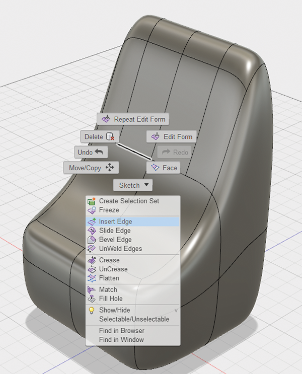
Figure 7-6: Select an edge, right-click, and choose Insert Edge.
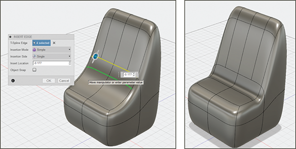
Figure 7-7: Change the chair’s shape with an inserted edge.
Bevel and Crease
Finesse the chair’s shape. Select an edge on the back and bevel it (Figure 7-8).
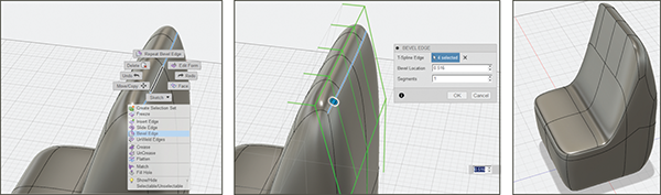
Figure 7-8: Bevel the back of the chair.
Then select an edge where the seat and back meet, right-click, and choose Crease (Figure 7-9). That will put a hard edge there instead of a rounded one (Figure 7-10).
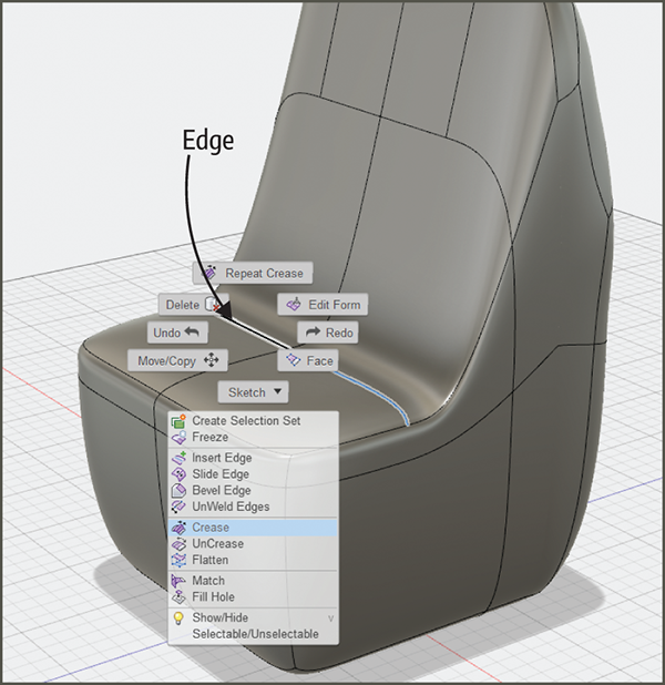
Figure 7-9: Select an edge and choose Crease.
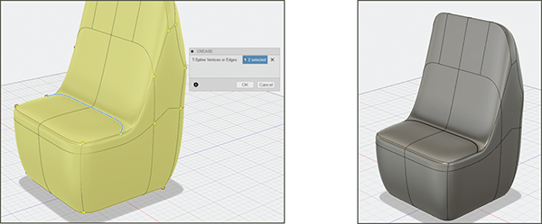
Figure 7-10: The chair’s shape has a hard (creased) edge now.
Short-Back Chair
Enter the Sculpt workspace and choose Create → Box, and then make a box equally sized on all axes (Figure 7-11). Then enter the Patch workspace (Figure 7-12). The subdivisions on the box will disappear.
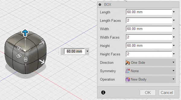
Figure 7-11: Make a box of equal proportions.
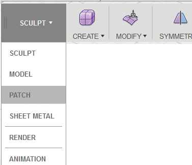
Figure 7-12: Enter the Patch workspace.
Delete Faces
Select the two adjacent faces shown in Figure 7-13 and press Delete.
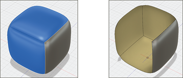
Figure 7-13: Delete the two adjacent faces.
Thicken Faces and Round the Edges
Select any remaining face, right-click, and choose Thicken. Then drag the arrow or type a specific thickness (Figure 7-14). To round the edges, press and hold the Shift key and select the ones shown in Figure 7-15. Right-click, choose Fillet, and type or drag a fillet radius.
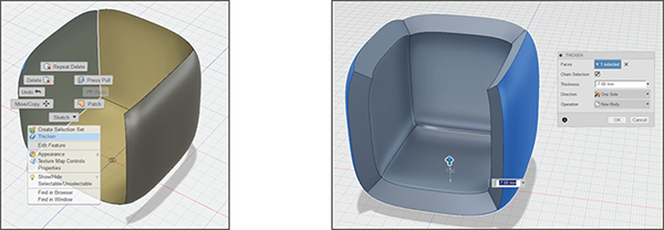
Figure 7-14: Thicken the chair.
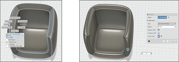
Figure 7-15: Select and fillet the edges.
Change Proportions
Let’s change this chair’s proportions. Drag a selection window around it. Click Modify → Scale, and set the dropdown arrow in the dialog box to Non Uniform (Figure 7-16). Then push the z-axis arrow down (Figure 7-17).
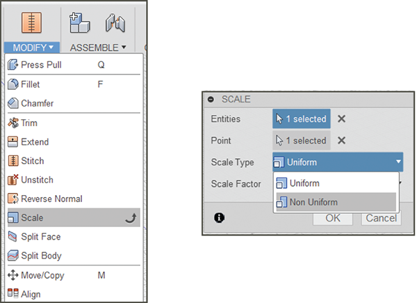
Figure 7-16: Click Scale → Non Uniform.
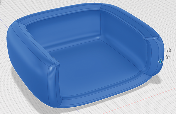
Figure 7-17: Adjust the height with the z-axis arrow.
Vase
Enter the Sculpt workspace and choose Create→ Cylinder; then make a tall cylinder. Double-click an edge at the bottom to select the whole ring (Figure 7-18). Right-click one of the selected edges, choose Edit Form, and drag the ring out with the manipulator’s center button to deform it (Figure 7-19).
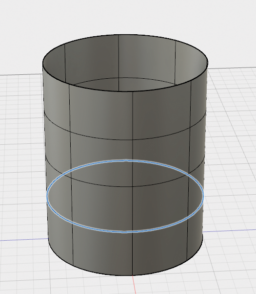
Figure 7-18: Make a cylinder and double-click an edge to select the whole ring.
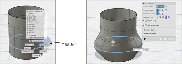
Figure 7-19: Edit the cylinder’s form.
Fill and Straighten the Bottom
Double-click an edge on the bottom of the cylinder to select the whole ring. Then click Modify → Fill Hole (Figure 7-20). The hole will close. The bottom will be rounded, so click Modify → Crease to make it flat (Figure 7-21).
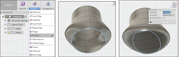
Figure 7-20: Fill the hole at the bottom of the cylinder.
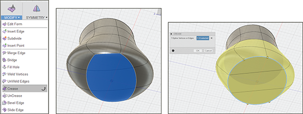
Figure 7-21: Crease the bottom to make it flat.
Attach an STL File to the Vase
Let’s jazz this vase up with an imported STL file of a face. Figure 7-22 shows a file I downloaded from thingiverse.com. Enter the Model workspace and click Insert → Insert Mesh (Figure 7-23). Use the manipulators to position it as shown in Figure 7-24. Scale it down if needed by selecting it and clicking Modify → Scale.
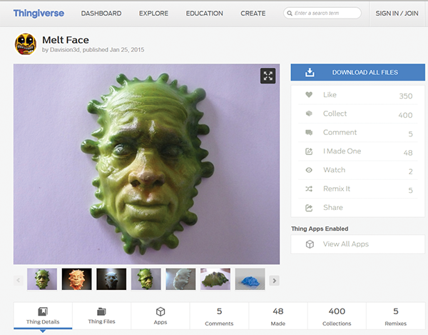
Figure 7-22: A file at thingiverse.com
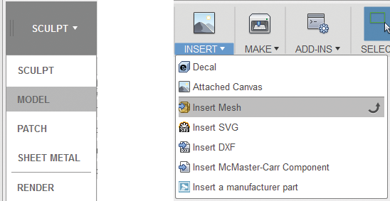
Figure 7-23: Insert the STL file.
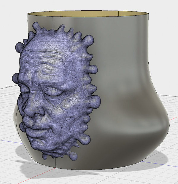
Figure 7-24: Position the STL file on the vase.
Reduce the STL File’s Polygon Count
The face file has a very large number of polygons, as you can see from the dense mesh. This means the Mesh to BRep conversion tool won’t work, so the file can’t be edited. To make the polygon count smaller, enter the Mesh workspace, if Fusion didn’t already default to it when you inserted the file (Figure 7-25). If the Mesh workspace doesn’t appear, you might have to enable it in the Preferences menu.
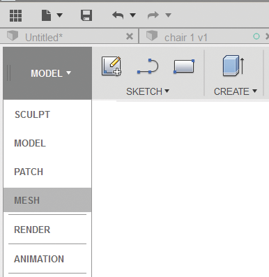
Figure 7-25: Enter the Mesh workspace.
Select the face through its Browser entry and then click Modify → Reduce. A dialog box will appear (Figure 7-26).
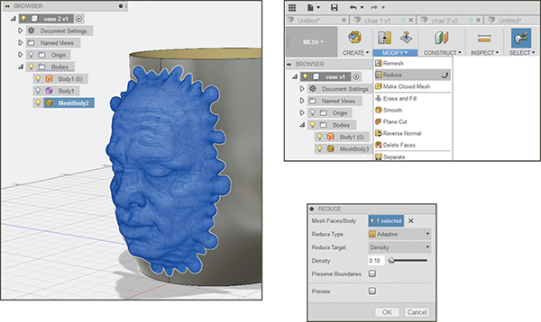
Figure 7-26: Select the file and click Modify → Reduce.
The dropdown menus offer adaptive (preserves the shape) or uniform (removes polygons uniformly) options. You can also adjust density, face count, and tolerance—all three, not just one. I changed the density, which controls how close the changed polygon edges are to the original edges. The smaller the number you enter, the less dense the file will be. I typed .10; Figure 7-27 shows the result.
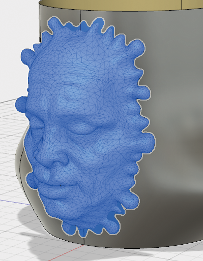
Figure 7-27: The reduced file
Optional: Convert to BRep
You can edit the file in the Mesh menu or you can convert it to a solid file to edit it in the Model workspace. It just depends on the kind of edits you want to do. To alter it as a solid, select it, right-click, and choose Mesh to BRep. If the file has a low enough polygon count and has no flaws, it will convert (Figure 7-28). You might get a message saying it will take a while; click and in a few minutes you should have your result.
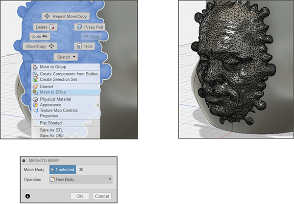
Figure 7-28: Convert the mesh file to a solid file if you want to edit it in the Model workspace.
Thicken in Model Space
Thicken the vase now. Thickening it in the Model (parametric) workspace enables you to edit it later. Select both the bottom and one side face (press and hold Shift), right-click, and choose Thicken. Then drag the arrow or type a number (Figure 7-29). In this case, I thickened it enough to cover the portion of the face that protruded through the vase’s interior.
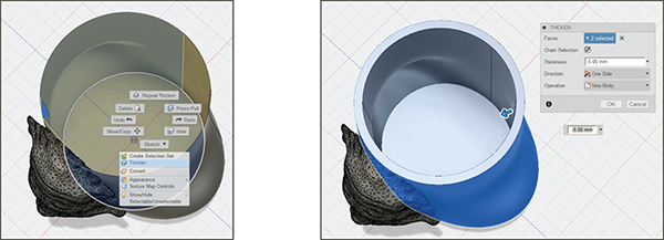
Figure 7-29: Thicken the vase.
Repair Flaws
Whether the face file is kept as a mesh or converted to solid, it, like most meshes, typically needs some repair to be 3D-printable. One program might fix it, or you might have to fix it with multiple programs.
In this case, I converted the face file to a solid with the Mesh to BRep tool. Then I exported the whole vase as an STL file and imported that STL file into Autodesk Meshmixer (meshmixer.com). There, I ran the Inspector tool. It found multiple flaws and fixed all but one (Figure 7-30). I exported it as an STL file from Meshmixer and imported it into Tinkercad (tinkercad.com), an Autodesk web app that automatically fixes STL files upon import (Figure 7-31). Then I exported an STL file from Tinkercad and reimported it into Meshmixer to make sure it was fixed. That flaw was indeed fixed, but Tinkercad added a few more flaws! Meshmixer was able to fix those, however, and I exported it as an STL. Finally, I sliced that STL with MakerBot software and printed it on a MakerBot Replicator 2 with Hatchbox filament (Figure 7-32).
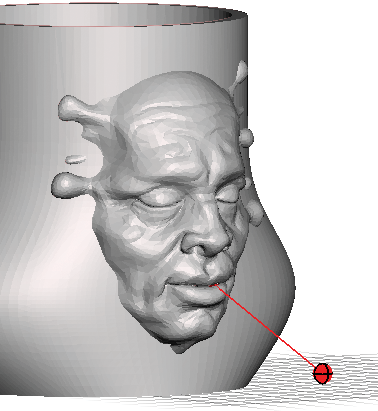
Figure 7-30: The red pin shows the flaw Meshmixer couldn’t fix.
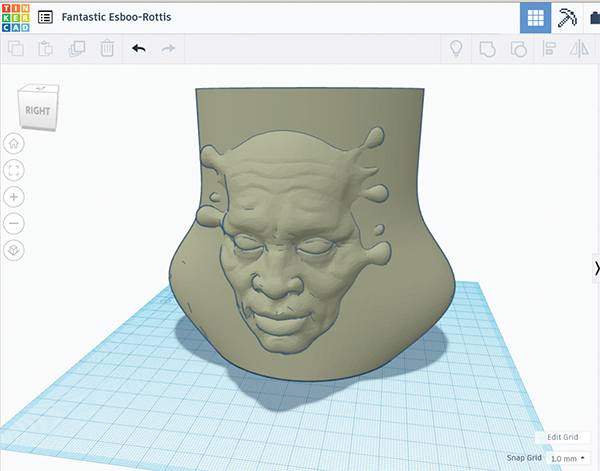
Figure 7-31: The file imported into Tinkercad, which fixes flaws upon import.
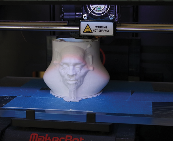
Figure 7-32: The vase under construction with supports, raft, and a 10% infill