
11
2D Layout
In this chapter, we’ll turn the Chapter 9 planetary gear set into a sheet of orthographic, scaled drawings. Such documentation is needed for shop fabrication or to prepare drawings suitable for a CNC cutting machine.
Convert Bodies to Components
Open the gear model. Convert all bodies in the file into components. Although solid bodies can enter the drawing workspace unconverted, they lack full functionality there. Mesh, T-spline, and surface bodies will not enter the drawing workspace at all.
Enter the Drawing Workspace
Click the Workspace menu and then select Drawing → From Design. Figure 11-1 shows two ways to do this. If the Fusion file was never saved, you’ll be asked to do so now. Then a dialog box will appear (Figure 11-2). Note the Full Assembly option. If you uncheck it, you can select individual components instead of bringing the whole file in. Hold down the Shift or Ctrl key to make multiple selections.
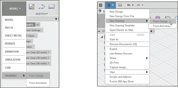
Figure 11-1: There are two ways to enter the Drawing workspace.
You can also choose a template from scratch or browse for one; choose the ISO or ASME standard, choose inches or millimeter units, and choose the sheet size. We’ll use the default size. The sheet size can be changed after you create a drawing, but the standard and units cannot. Then click OK to enter the Drawing workspace. When you do, a tab for this drawing will appear at the top of the screen.

Figure 11-2: Choose options.
Base Views
When you enter the workspace, a base view, also called the parent view, of the gear will appear. This is a 2D view derived directly from the model. There will also be a dialog box with options for, among other things, orientation, style, and scale. Here you choose to display the base view from the top, front, or side, or as an isometric (a 3D view). You can also choose the scale (Figure 11-3). Shown is a 1:5 scale, which can be changed on each base view, or changed on this view later.
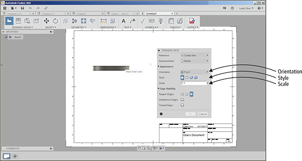
Figure 11-3: Enter the workspace, and a base view and dialog box appear.
Create Multiple Base Views
To bring in another base view, go to the Drawing Views menu. Click the dropdown arrow, click Base View, and bring a second view into the workspace (Figure 11-4).
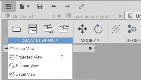
Figure 11-4: Bring another base view in through the Drawing Views menu.
Edit a Base View
When you click a base view, a dashed blue box surrounds it, indicating it’s highlighted and can be edited. Right-click to bring up a context menu (Figure 11-5). Click Edit View to open the Drawing View box. I clicked the Orientation dropdown arrow and then clicked TOP. The highlighted view changed from the default side view to a top view. Figure 11-6 shows it as an isometric view. To delete it, or any other view, just highlight it and press the Delete key.

Figure 11-5: Changing a base view from the default side view to a top view

Figure 11-6: An isometric view of the gear
In Figure 11-5’s middle graphic you can see that the top view of the gear overlaps the side view. Click that side view to bring up its blue editing box. A small gray square will appear within the box; drag the square to relocate the view (Figure 11-7).

Figure 11-7: Move a view by dragging it when the blue editing box is open.
Projected View
A projected view is one generated from a base view, and it inherits its properties from the base view it’s projected from. To project one view from another, choose Drawing Views → Projected View. Then click the base view and the location you want to place the projected view (Figure 11-8). The projected view will automatically position itself depending on where it is in relation to the base view.

Figure 11-8: A side view projected from the top view
After placing the projected view, you can change its properties by double-clicking it. A View Properties dialog box will appear; choose options. When you click OK, the projected view will automatically update.
Section View
A section view is a slice through the whole model, which allows you to see inside it. To make one, choose Drawing Views → Section View. Click the plane view or parent face to start, click two points on the plane or face where you want to make the slice, and then press Enter (Figure 11-9). Select the newly created section and drag to place (Figure 11-10).
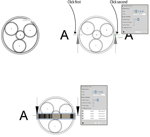
Figure 11-9: Cutting a section view

Figure 11-10: Drag to relocate the section view.
Center Line
To put a center line through a view, choose Geometry → Centerline. Then click two straight edges. A center line appears between them. Drag the arrows on each end to make the center line longer (Figure 11-11). If a center line is too short, it won’t appear as a center line type.

Figure 11-11: Putting a center line in a base view
Dimensions
Dimensions are notes on lines that describe size. To add dimensions to a view, click Dimensions. There are many options in this menu; we’ll choose Linear Dimension (Figure 11-12).
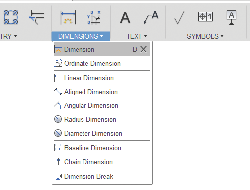
Figure 11-12: The Dimension menu and its options
Click the item to be dimensioned. You can click points, edges, or existing dimensions, or click two points. Then click to place the dimension line (Figure 11-13), which also finishes the operation. Double-click the dimension line after you’ve set it to bring up a preferences dialog box.
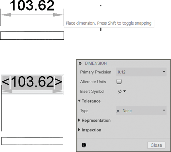
Figure 11-13: Adding a dimension line to a base view
Text and Leader Text
To add text, click Text (Figure 11-14). The Text option places text anywhere on the workspace. Click to set the corners of the text box, and a dialog box appears with options for font and size. Type the text and then either click outside the text box to finish or click Close in the dialog box (Figure 11-15).

Figure 11-14: The Text menu

Figure 11-15: Adding text to the workspace
The Leader option attaches an arrow to the text. Click the arrowhead location, click the text location, and then type the text. Click outside the text box to finish (Figure 11-16).

Figure 11-16: Adding leader text to a base view
Callouts
To add a callout (an identification symbol) to a base view, choose Symbols → Datum Identifier (Figure 11-17). Then click the place you want to add it and type in the text field (Figure 11-18).
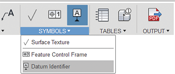
Figure 11-17: Choosing Symbols → Datum Identifier
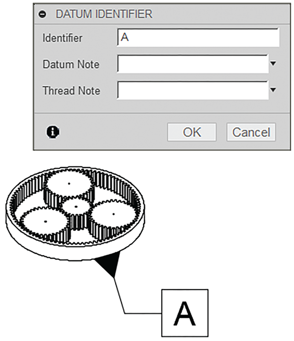
Figure 11-18: Adding a callout to a base view
Tables
A table is a parts list for a single component, assembly, sheet metal flat pattern, or animation reference (a drawing created from an animation). Choose Tables → Table (Figure 11-19). A table will immediately generate for the whole assembly; drag to place it where you want (Figure 11-20). Select the table and drag gray squares in each column to adjust their width. To move the whole table, drag a selection window around it and click Modify → Move at the top of the screen.
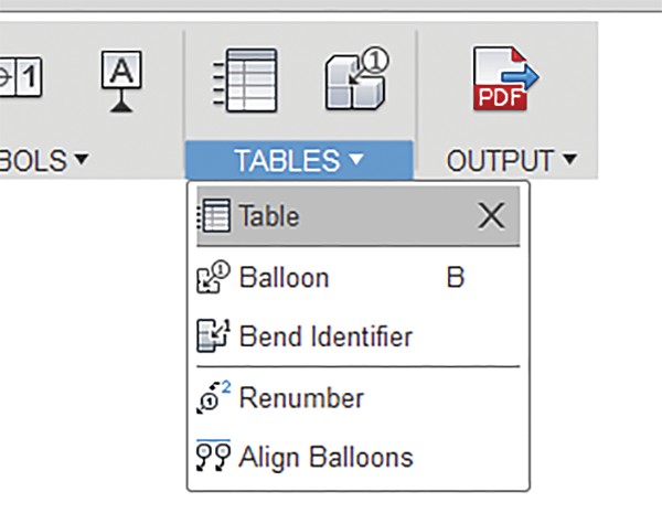
Figure 11-19: Choosing Tables → Table

Figure 11-20: Automatically generate a table for the whole assembly.
You can generate balloon callouts to coordinate with the table by choosing Table → Balloon and then clicking a specific component (Figure 11-21).

Figure 11-21: A balloon callout made from the Tables menu
Title Block
The default sheet we chose has a built-in title block. Click that title block to bring up a window with text fields into which you can type your specific information (Figure 11-22).

Figure 11-22: Click the title block to open this window.
Export the Sheet
Once the sheet looks as you want it, click Output (Figure 11-23) andsave it as a PDF, DWG, or CSV file. The first two formats are files needed to manufacture the part. If your goal is to cut one gear out on a CNC machine, just send a model of one gear to the Drawing workspace and set it as a top view. The third format is a plain text parts list, which you can see in Figure 11-23. To exit, just close the tab at the top of the screen (Figure 11-24). The drawing file will close and a thumbnail will appear in Fusion’s Data panel alongside all the model files.

Figure 11-23: Save the sheet as a PDF, DWG, or CSV file.
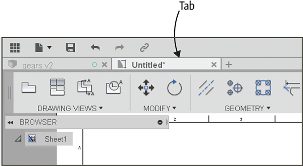
Figure 11-24: Close the file’s tab to exit.