
Photography by Larry Cotton
TIME-BASED DEVICES
Transplant a heartbeat from cheap alarm clocks.
Some projects need a nice, steady, low-voltage pulse at a constant rate. This is relatively easy to do with the ubiquitous 555 IC, but what’s not so easy is keeping a 555-based circuit accurate to within a few seconds a month. For that, you’re better off just gutting a cheap travel clock. This will give you an easy module that generates ultraaccurate pulses at 1Hz — something which, in my opinion, is more valuable than telling time.
Not just any clock will do, however: it should run on one battery (usually AA size) and have hands, not an LED readout. If it has a second hand, it must jerk forward every second (most do), rather than sweep. Clocks like this are easy to disassemble and cost less than $5 at some retailers. They all use the same basic mechanism: a 32,768Hz quartz-crystal oscillator, along with the electronic and mechanical parts that convert its oscillations to clock ticks.
Disassembly demands a bit of finesse. Although you’re not tinkering with a fine Swiss watch, you are filleting some fairly delicate clock guts. What you’re looking for is the electromagnet (solenoid), which turns the first gear in the gear train.
Your surgical procedure will depend on whether your project just needs the electronic pulse generator, or a clock with working hands that continues to tell time. If you just need the clock’s ticker, you can disassemble without worrying about reassembly, and throw away the gears, hands, and even the electromagnet.
Here are the steps I followed with my clock. Yours may differ depending on its age. I’ve also successfully used wall clocks, which also come apart easily. The electromagnet in a wall clock may not be as readily removable, but it’s a piece of cake to solder new wires to, and it will work fine with the electromagnet in place.

Fig. A: Lifting out the electromagnet reveals the two wires you need to splice into.

Fig. B: Clearance hole cut through clock’s front panel.

Fig. C: New wires to your own circuit connect to the electromagnet through the clearance hole in the now-bare clock face.
1. Remove the battery cover.
2. Remove the battery.
3. Remove the clear face cover.
4. Pull off the hands.
5. Remove a shaft nut and washer. This depends somewhat on the quality of the clock, and may not need to be done.
6. Pull off any setting knobs that attach to rear protrusions.
7. Remove clock face and mechanism. You may have to release the boxy little clock mechanism (roughly 2"×2"×½") from the main body of the clock; you may also need to remove a printed clock face in order to access parts, and make a wire-clearance hole. Read the remaining instructions to help you decide what to do.
8. Pry off the back. It’s usually just snap-fitted together. Otherwise, carefully Dremel (is that a verb?) the case open. In some cases, the back piece holds tiny plastic gears in place, so they may fly out if you’re not careful. But if you don’t need the hands, don’t sweat the flying gears.
9. Carefully lift out the little gear and the electromagnet. The electromagnet has fine copper wire wound on it, and the first gear in the train is surrounded by steel fingers. Two wires are attached to the magnet, usually red and black.
10. Discard the electromagnet. If you don’t need the hands, you can do this by clipping or unsoldering its wires.
11. Pry the face off if you haven’t already done so. Mine was attached with tape. You may have to route 2 new wires through the front of the clock.
12. With a Dremel and small bit, make a small hole in the plastic housing. You want to do this just below where the 2 solder terminals for the electromagnet’s wires were. This will clear the new wires you will install. Alternately, if you have room, you may be able to route the wires around the circuit board and out the back.
13. Carefully solder 2 new thin, flexible, insulated wires in place. You can do this to either the electromagnet or just to the 2 wires. Polarity isn’t important. You may have to mechanically attach your new wires with tiny loops before soldering.
14. Route the wires away from the clock. Go through the hole in the housing, if necessary. If you need the clock’s hands, reinstall the first gear out, and reverse your disassembly.

Fig. D: Moebius clock advances a single-sided paper loop with printed times.

Fig. E: Dual-dial clock shows hours above and minutes below; hands swing back at the ends of their arcs.

Fig. F: Simple transistor circuit boosts clock pulse up to 5V, for driving a stepper motor or interfacing with other 5V-based electronics.
The 2 wires you connected to the clock will put out a very short electrical pulse every second. Some clocks alternate a strong every-othersecond pulse with a weak and less usable one. You can use a cheap NPN transistor such as a 2N2222 to amplify this pulse, to interface with the next stage of electronics. You can also add divider ICs, such as a 4017, to increase time between pulses to almost any length you wish.
I’ve transplanted tickers successfully into several alterna-clocks I’ve built. For my Moebius clock, I sent the amplified pulse into a stepper motor which advances a Moebius strip tape with times printed on it. For my dual-dial and arc clocks, I send the pulse to the motor through a BASIC Stamp microprocessor, which keeps track of the time. When it becomes 12:59:59, the code triggers a subroutine that quickly runs the hands (or arcs) backward and resets the time to 1:00 — which is always fun to wait for and watch.
Larry Cotton is a retired power-tool engineer, musician, and part-time math teacher who just happens to have a bit of extra time on his hands in New Bern, N.C.

Photography by Tom Jennings
METAL ETCHING
Chemically carve detailed text or line art onto brass or copper.
I make forged, obsolete laboratory instruments as art pieces. To render intricate line art and text onto metal panels, I use the same chemical etching process that creates printed circuit boards. The etched areas are only a few thousandths of an inch deep, but they give a clear image that you can fill in with paint or enamel. If you’re building the panels into an object, you should etch them before bending them or drilling any holes. This process only works on flat, solid metal surfaces.
Be warned: This is a highly variable process. I’ve done immaculately perfect panels with smooth 10-micron lines, but most often there are flaws in the materials, rough areas, loss of resolution, or other problems. Cleanliness and care get better results, but the trick is to go with the flow, and work with what you get.
Create the Transparency
You can create your artwork by hand or digitally, but it needs to be rendered as a mirror-image of your final image, in solid black on transparent film. Use black ink only, and print on the coated side, not the shiny side.
Illustrator, the GIMP, Photoshop, and other graphical utilities let you threshold any images into pure black-and-white, to make them suitable for etching. Then use Reverse to produce a printable mirror-image. You want the printed image to read correctly when you’re looking at it with the ink-and-coating side down.
I do my artwork in Adobe Illustrator, and print it on HP transparency film in my Epson 777 inkjet. When my art is ready, I load the transparency film, hit Save, reverse the image, Print, then Undo.
MATERIALS
Artwork
Transparency film
Printer or copier to render your artwork onto the transparency film
Copper or brass plate Zinc will probably also work, but don’t use iron or steel, and definitely not aluminum, which is dangerously incompatible with the etchant.
Lamp with 500W photoflood lamp bulb (3200º Kelvin) and reflector on improvised stand over work surface
Dishwashing liquid
Sandpaper and fine abrasives of varying grits up to 600 or finer You can also use red and white auto polish, cheap from any auto parts store.
Nitrile or other chemical-protective gloves
Protective eyewear
Pane of glass big enough to cover metal plate
Pyrex dishes (2) big enough to hold the metal plate
Piece of clean wood or other “carrier” for the metal plate so you can move it without touching it
A drawer or other clean, dry, and absolutely dark place to put the plate
Photo timer or stopwatch that’s easy to read in the dark
CHEMICALS
All are available from GC Electronics (gcwaldom.com) or Minute Man Electronics (minute-man.com)
ER-71 negative acting photo resist liquid in a spray bottle
ER-8 photo etch developer
Ferric chloride etchant Electroless tin plating solution (optional)

WARNING: The light-sensitive chemicals are flammable, and the ferric chloride etchant is extremely dangerous — it burns and stains skin, fabric, wood, and reacts violently with aluminum.
Polish the Metal Plate
To receive the photo-resist coating, the metal must be absolutely smooth and grease-free; a single fingerprint can ruin the surface.
1. Sand the surface with increasingly fine sandpaper, ending up with 600 or 1500 grit. Follow up with red and white automotive polishing compounds.
2. Wash the entire plate spotlessly clean with hand dishwashing soap, and dry with paper towels. Don’t touch the surface!
3. Place the plate on a wood block or other carrier, bring it to a protected place, and let it dry. Be sure to handle the plate by the edges only. You can dry it in a clean, non-greasy oven at 120-150ºF for 20 minutes, or leave it in a drawer for a few hours.
Set Up Your Work Area
The coating, exposure, and development steps need to be performed in a darkened room or under a red darkroom light, so it’s important to find a good spot and set up ahead of time. And because solvents are involved, the area also needs decent ventilation. A kitchen sink by a back door at night would work.
1. In an area that’s well-ventilated and can be made dark, set up the 3200º Kelvin photoflood lamp in the reflector, such that it shines straight down onto a flat tabletop, 18" from the table surface, plus or minus an inch. The lamp has a very short life (6 hours) and it generates a lot of heat. It exceeds the ratings of most cheap aluminum reflectors, but that was not a problem for me. It’s not left on for long enough to do any harm that I noticed.
2. Put your photo timer or stopwatch someplace accessible and visible.
3. Clean and dry the sheet of window glass so that it’s spotless on both sides.
Coat the Plate with Emulsion
This step coats the plate with a very thin light-sensitive film, and you need to do it in the dark. Be sure to keep the ER-71 liquid in its box when not in use.
1. Holding the prepared metal only by the carrier, tilt it, and pump-spray the surface with ER-71 photo resist liquid until it is soaking wet and excess liquid drips off one corner.

Fig. A: Print the etch image backwards onto a sheet of transparency film.

Fig. B: Clean and polish the metal (copper or brass) surface. A single fingerprint can ruin the transfer.

Fig. C: Sensitize the metal by coating it with photo emulsion liquid. Keep the spray bottle out of the light when not in use.
2. Let the excess drip for 12 seconds, then hold it flat and look for 100% perfect wet coverage. If you see fisheyes, or the liquid pulls away from the metal, it wasn’t clean enough. In this case, wipe off what you can, and finish cleaning with some ER-8 developer on a rag. Clean thoroughly and try again.
3. Put the plate in a dark, dry, flat, and level storage space, like a drawer. As the coating dries, it will level out and harden. Let it dry for 30 minutes.
4. A second coat isn’t usually needed, but I’ve occasionally used one when the coating seemed too thin or etching didn’t work the first time. Wait at least 1 hour before applying a second coat.
Expose the Plate to Light
This step also needs to be performed in the dark or under dim red light.
1. Place the metal plate on the table, photocoating side up. If your carrier is very thick, raise the lamp to compensate, so that it’s 18" above the object.
2. Place and carefully align your artwork onto the plate so that the image is righted. Because we printed the image reversed, the inked image now lies right up against the coated metal. That’s good. If it were printed the other way, the transparency film would lie between the ink and the metal, which greatly lowers resolution.
3. Carefully place the cleaned sheet of glass over the transparency to hold it flat against the coated metal. Recheck image alignment.
4. Turn the 3200ºK photoflood lamp on for 4 minutes, then switch it off. You may need to experiment with exposure time if you use a different lamp or height.
5. Keep the exposed plate in the dark until it’s in the developer bath (next step).
Develop the Image
Developing the plate causes the parts that were exposed to the light to harden into a resist coating, and the parts that were directly under the black ink to wash away, leaving bare, exposed metal. You need to continue working in the dark until the plate is in the developer bath.
1. Place the exposed object in Pyrex dish #1, coated side up, and pour on enough ER-8 developer to cover it. Used ER-8 is fine for this step. Once the plate is covered, you can turn the lights on.
2. Rock the dish gently so that the ER-8 sloshes over the coated surface for 45 seconds.

Fig. D: Expose the coated metal plate for 4 minutes under a 500W photoflood lamp, with the reflector positioned 18" above. Don’t worry if the reflector isn’t rated for a bulb that hot; it isn’t on for long enough to matter.
Fig. E: During exposure, the transparency should be positioned with its inked side directly against the metal, pressed down with a plate of glass.
3. Remove the object from the dish, draining developer back into the dish.
4. Place the object into Pyrex dish #2, and pour in enough new, fresh ER-8 to just cover the surface. The exposed coating is very soft and delicate at this point.
5. Very gently rock the dish for 10 seconds. Lift the object out of the dish and let it drain, handling it only by the edges.
6. The coating is now no longer light-sensitive, but it is invisible and extremely delicate until it’s dry. Do not touch! Set the object aside to dry fully, for 1 hour.
NOTE: ER-8 developer is reusable an unknown number of times, probably a dozen or more. The second brief dip in fresh ER-8 just rinses off any crud that was in the used ER-8 from the main step. This stretches the life of the developer. I keep my used ER-8 in a clean glass jar.
Find and Fix Flaws in the Coating
If the exposure process failed, etching will just roughen the plate’s surface and you’ll have to sand it all off and start over. Here’s how to make the coating pattern visible; then check it and correct any flaws before etching.
1. Fill a Pyrex dish with water and add just a few drops of etchant.
2. Immerse the plate in the dish; the coated areas will remain shiny while the open areas will faintly etch, making the coating pattern visible.
3. Compare the coating pattern to your original artwork and look for areas where the plate should be etched, but are still shiny (coated), and vice versa. For areas that should be etched but weren’t, use a knife to carefully scrape the coating away. For areas that should be coated but are exposed, cover them using a paint pen or pieces of tape trimmed to shape. Correcting a few flaws this way is fine, but if large portions of your design didn’t make it through, you’re better off repolishing the plate and starting over.
4. You can discard this very weak etchant solution by pouring it down the drain and following it with copious amounts of water.
Etch the Metal
This step completes the process. The ferric chloride etchant eats away metal from the object anywhere that coating was not exposed to light.
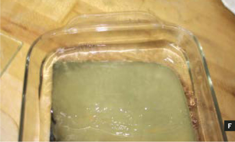
Fig. F: After exposure, develop the plate in 2 baths of ER-8 developer. Used ER-8 liquid is fine for the first bath.

Fig. G: Etch the plate in warmed ferric chloride solution, wearing gloves and eye protection at all times.
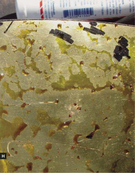
Fig. H: Monitor progress during etching by lifting the plate out of the etchant and inspecting the surface.
WARNING: FERRIC CHLORIDE ETCHANT IS VERY TOXIC AND CORROSIVE.
It eats people, cloth, and wood, as well as metal. It will kill your pets and your plants. You cannot dump it into any sewer system, since it eats through pipes. Store it in its original bottle, and when it’s spent, take it to a chemical disposal site. When ferric chloride contacts aluminum, it makes heat, splatters everywhere, and ruins the metal.
These are not wimpy warnings. Etchant is dangerous stuff. Wear chemical gloves and protective eyewear, and have someone around in case of emergency.
1. Cover the bottom and sides of the plate with packing tape or spray paint, to protect it from being etched.
2. Warm up the etchant to about 120ºF by putting the sealed container into a bucket of hot water for 30 minutes. Etching goes faster at elevated temperatures.
3. If the metal plate is heavy, warm it to about the same temperature. (If it’s thin, don’t bother.)
4. Put the plate into a Pyrex dish and pour undiluted etchant to cover it completely, as much as possible without overflowing.
5. Rock the dish slowly but constantly to etch away metal. I put a pencil under the Pyrex dish to make it easier.
6. The amount of time is highly variable, and depends on how much metal you want removed. With chemical gloves on, you can lift the object out to inspect it. Etching for a full hour might get you 0.02" of depth, which may not sound like much, but it’s quite striking and effective. You can feel it, and it’s plenty deep to hold paint.
7. When done, remove the object from the bath and let it drain completely into the Pyrex dish. Then rinse it off in a sink with copious flowing water, and wash with hand dishwashing soap.
8. Your item is done! The resist coating can be removed with a bit of lacquer thinner on a cotton ball, or with mild abrasives like the polishing compounds used earlier.
Plating and Painting
So far, the photographs in this article have been showing the brass plate from my Model 11d Nixie clock. Another example, probably the best etched panel I’ve done, and one of the more detailed, is from my Model 11b Nixie clock.

Fig. I: Another panel, copper this time, fresh out of the etchant bath and washed off.

Fig. J: An electroless plating bath tin-plates the etched copper panel, giving it a more neutral color.

Fig. K: Filling in the etched arrow details with a fine paintbrush and black enamel paint.
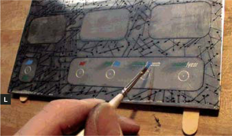
Fig. L: Filling in the color detail with more enamel.
This was a copper plate, which I tin-plated after etching using electroless plating solution. After removing the plate from the tin bath, the tin plating was dull.
I polished it with dry cotton balls, then used a small paintbrush to fill the etched lines with enamel paint (One Shot brand). I used tiny scraps of paper to carefully wipe the enamel filling flush with the surface, then polished off the excess with small scraps of plain copy paper.
After the paint dried, I shaped the panel by drilling holes for the switch and buttons, and filing out the rectangular areas for the display.
I also used tin-plated copper, painted with black enamel, for my Model 13, shown at right. Instead of using Nixie tubes, this clock shows the time and date with an analog needle gauge.

Tom Jennings ([email protected]) is an artist with a background in technology.

Photography by Sam Murphy
ELEGANT PLYWOOD COFFEE TABLE
Making furniture with no nails, screws, or glue.
I’ve been interested in designing furniture for a long time. When I needed some of my own, I decided to build a set out of ¾" plywood. I chose to work with birch veneer plywood because it reminds me of Scandinavian furniture, which has a clean, elegant style that I love.
Having done a lot of moving in the last few years, I also wanted to make the furniture easy to assemble without any fasteners. To accomplish this, I designed each component piece with slots that mate with one another and hold the whole piece together. Not having fasteners makes the furniture easy to pack up and transport — each item breaks down into a stack of flat boards. Finally, I didn’t want to create any waste, so each piece is cut exactly from a half sheet of plywood.
Here’s how to make an elegant coffee table with a few simple cuts, using a drill, jigsaw or circular saw, clamps, and other familiar tools.
1. Get the wood.
Obtain a 4’×4’ piece of ¾" plywood that is in good condition and free from warping and knots. You’ll also need four 1"×¼" wooden pegs. Different grades of plywood vary in price, ranging from rough particleboard to finely veneered and pre-sanded. This project will work with any type. I chose Baltic birch veneered 5-ply from a local hardware store. If your sheet does have a knot or two, plan your production so that they wind up on the underside, rather than facing out. After sanding and painting, the piece will look great.

Inset: Pattern and dimensions for table’s 4 component pieces. Tabletop, brace, and 2 legs are all cut from a single 4’×4’ sheet of plywood, with no waste.
SAFETY FIRST! Whenever working with or handling wood it’s a good idea to use gloves to protect your hands from getting splinters. Wear safety goggles and hearing protection while using any tools, and always secure the material you’re working with to a stationary object using clamps or a vice. It’s best to work with a partner, and it also makes projects more fun.
2. Measure the wood.
Referring to the pattern above, measure and mark your plywood along lines 1, 2, and 3. These divide the sheet into 4 pieces: a tabletop, a brace, and 2 legs.
To ensure accuracy in measuring, the trick is to measure from 2 or 3 different directions and make sure that they all yield the same result. I often measure cuts I’m about to make from opposite ends of the plywood, and then use a square to ensure their proper angle against the edge of the material.
TIP: To make clean, straight cuts with a handheld jigsaw or circular saw, clamp down a fence at either end of the material and run it along the edge you want to cut. A fence is simply a straight, solid object that provides an edge for your tool to rest against.
3. Cut the wood into pieces.
These first cuts break the unwieldy 4’×4’ sheet of plywood into more manageable pieces. I used a handheld jigsaw.
Cut 1 Halve the plywood sheet to produce two 4’×2’ pieces. One piece will be the tabletop and the second one will become the legs and the brace that holds the other 3 parts together.
Cut 2 Make a cut parallel to the first that’s 5"-10" in from the edge. This creates a narrow 48" piece that will serve as the table’s brace. The wider you make this piece, the lower and more stable your table will be. I made a taller table by cutting a 5" brace piece.
Cut 3 Clamp the larger piece left over from Cut 2, and cut it evenly in half, perpendicular to the first 2 cuts. With my table’s measurements, this turned a 19"×48" piece into two 19"×24" legs.

When finished, the pieces of the table should look like this. Disassembled as shown in the inset and stacked together, they’re a cinch to store and transport. To assemble the table, slide the slots in the legs into the slots in the underside of the brace, as shown here. Then pop on the tabletop.
4. Cut the slots.
Cut the 4 slots, following the measurements shown on the previous page. Note that although the plywood is labeled as ¾", its actual thickness may vary. So for each slot, you should first measure the thickness of the plywood it will fit around (calipers are handy for this), and make the slot a few hundredths of an inch larger.
There are several ways to cut slots with handheld tools. One method is to use a ¾" hole saw or paddle drill bit and drill a hole at the inside end of the “soon-to-be slot.” Then cut 2 parallel lines, tangent to the hole, out to the edge of the board.
Another way is to drill holes at the inside corners of the slot that are just large enough to admit a jigsaw blade, then jigsaw out from those.
The third method is to cut a slot straight out using a router and a ¾" router bit. This is the best method, provided you have the equipment.
5. Test assemble, and set the pegs.
Slide the legs and brace together, to make sure they all fit. Along the top edge of each leg piece, measure 2" in from each end and mark a point centered on the edge of the plywood. Disassemble the pieces, and drill ¼" holes at each of these 4 points, ½" deep. On the underside of the tabletop, mark 4 corresponding points and drill 3/8" receiving holes for the pegs ½" deep. I marked locations by sliding pieces of pencil into the leg holes and centering the tabletop on top.
6. Finish the wood.
You have many creative choices when it comes to finishing your furniture. You can sand the edges, finish them with a router, or level them square. You also need to seal the wood, especially if you intend to use this as a coffee table where you will serve beverages. I used a water-based stain and 3 coats of high-gloss finish for the product, but there are other options. Ask the friendly people at your neighborhood paint store for advice.
Bonus: Now that you know how to make an awesome coffee table, you can use the same general method to make a bench or a desk or a dining room table or a stool. Go to town!
Andy Lee (andyleedesign.com) is a mechanical engineer and product designer. He specializes in consumer and household goods.
Photography by Ross Orr
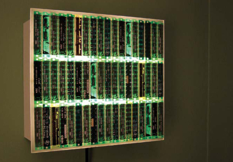
THE BYTELIGHT
Make a high-tech mood light from a fluorescent lamp and 54 obsolete SIMMs.
Several years back, I had a volunteer gig with a local charity. My job was to take old Macs that had been donated, and jolt them back to life so they could be resold at our weekly rummage sale.
In those days, the low-end machines often came in with 1 or 2MB of memory — that M is no typo, you youngsters! — and I considered it a great victory if I could scrounge enough memory to upgrade them to 4 or 8MB. (I can also remember fitting System 6 on an 800K floppy — but Grandpa will save that story for bedtime another day.) Anyway, we routinely yanked out 256K SIMMs doing these upgrades, and I eventually accumulated a whole sack of them.
I knew these chips were utterly useless, but could never bring myself to throw them out. I kept dwelling on the thousands of dollars that their original purchasers had undoubtedly spent on them. Plus, these little wafers were kind of beautiful: each had its own subtly different color, delicate circuit traces, and cryptic labeling. They were almost like jewelry. I felt I needed to do something to honor their now-defunct preciousness, and thus the ByteLight was born.
The idea is simple, and can be used with any “interesting” piece of circuitry that has outlived its usefulness, as long as a bit of light shines through it. You just need to construct a shallow light box. Fronting it with diffusing plexiglass lets you glue down multiple circuit boards using silicone sealant. You can buy white plexi, but I just used clear scrap I had on hand. Sanding both sides with fine sandpaper on an orbital sander gave it a nicely frosted surface.

Fig. A: Silicone glue attaches wafers to plexiglass, which is held above the rim of the light box by a threaded rod.

Fig. B: Wafers are glued chip side down to show tracery.

Fig. C: Removable light box back with lamp socket and compact fluorescent.

Fig. D: The sheet aluminum lining stapled into the box reflects and diffuses light.
I made my box from ½" plastic-faced particleboard from an old sink cabinet. (A tip for neat mitered corners: after cutting the bevels, lay the boards flat, end to end, and run packing tape across each joint. Apply glue, and fold the corners into place. The tape holds the joints in position.)
The front edges of the box are cut away at an angle, so they won’t cast shadows on the frosted panel. I added aluminum reflectors to even out the light, but that’s optional. For easier access when it’s time to change bulbs, I bolted the lamp socket to the removable back panel of the box. I also drilled a keyhole slot centered in the back panel, to make it easy to hang the finished box.
Use fluorescent lamps for your light source, to keep things cool. I used a 10W screw-base fluorescent, which puts out the same number of lumens as a 40W incandescent. Even so, I left a small gap between the plexiglass and the box to let heat escape. The box is sized to be 1" smaller than the height and width of the plexi, which eclipses the gap with a nice floating-plane look.
The trick to making the front float is to thread stubs of 10-24 rod into holes tapped in the plexiglass. Then drop these into holes in the box perimeter, drilled oversize and filled with silicone. I used kitchen matches to hold the gap spacing while waiting for the silicone to cure.
The power cable, appropriately enough, is also recycled from a computer. I snipped off its IEC connector, and wired it up to a screw-base lamp socket. The blue (or white) neutral wire in the cable should be connected to the shell of the socket. If your cord has a green or bare ground wire, you can connect that to any metal parts of the light box. Tie the cord into a knot inside the light box, so an accidental yank can’t pull it out.
If you’re laying out a grid of small boards like these SIMMs, it may turn out they aren’t exactly identical in size. So test your layout beforehand, and sand down the edges of the oddballs as needed. I decided I preferred their look with the component side down, to emphasize the patterns of the circuit traces, leaving the RAM chips themselves as ghostly outlines.
The result is a softly diffused green light — a nice ambience for late-night relaxing. And I’m pretty sure I’m the only person on my block with a 13.5-megabyte night light.
Ross Orr hacks low-tech gadgets and invasive plants in Ann Arbor, Mich.