
Photograph by Sparkle Labs
DIGITAL CLOCK
Programming PIC microcontrollers, part 3.
In parts 1 and 2 of our microcontroller primer (MAKE, Volume 04, page 158, “Microcontroller Programming,” and Volume 07, page 149, “Hello, World”), we got a PIC chip development system up and running, covered basic inputs and outputs, and left off by showing how to use a PIC chip by itself to control a simple pushbutton counter. In this article, we’ll show how to use a PIC along with other chips to make a digital clock.
Our two peripheral chips are the DS1305 Real Time Clock (RTC), which keeps track of the time, and the MAX7221, an LED display driver. Both are manufactured by Maxim Integrated Products, with datasheets available at maxim-ic.com. We’ll use the PDIP package versions, so they’ll fit into a breadboard.
Just like our microcontroller, these special-purpose ICs have settable 8-byte registers that determine how they function. But peripheral chips don’t store and run programs on their own, so we can’t upload code to them and set their registers directly. Instead, we’ll program our microcontroller to tell these chips what to do. The chips’ datasheets explain how the microcontroller can communicate with them, as well as how they need to be connected into our circuit.
ICs exchange data over numerous communications protocols. Our clock will use Serial Peripheral Interface (SPI), a simple serial binary protocol that requires just four pins on the microcontroller, plus one more for each additional peripheral device. One pin sends data out to the peripheral(s), one pin receives data, a clock pin pulses high and low to mark each new send/receive cycle, and the latch (or load) pins, one for each peripheral, switch the peripherals on and off. These pins and their connections are collectively known as the data bus.

The LED Display
First, let’s look at how to hook up our display driver to run the displays that will show our clock’s time. The MAX7221 datasheet explains that this IC is capable of driving up to eight 7-segment digit displays (or up to 64 LEDs in an 8×8 matrix). Referring to the pin description on page 5 of the datasheet, we see that pins 1, 12, and 13 are the data-in, latch, and clock pins, respectively; we’ll connect these to I/O pins on the PIC. Pin 18 connects to power through a resistor, the value of which limits the peak current that the chip supplies to the LEDs, to match the LED’s power needs and desired brightness. Pin 24 is data out (which we are not using). Pin 19 connects to +5 volts, and pins 4 and 9 go to ground. Physically, pins are numbered on ICs counterclockwise from pin 1, just to the left of the notch on top.
The remaining 16 pins connect to the LED displays themselves. Eight of these pins are the digit drivers, each of which connects to the common cathode of a single-digit display and sinks the current that runs to the segments of the digit that are “on.” The other 8 pins are the segment drivers, which supply current to all of the segments that share the same position on the displays.
To turn a digit on, you set the digit driver low for that digit. Then current will flow through from the segment drivers that are set high, and light the segments. Meanwhile, the driver scans through all the displays repeatedly, changing segment pins and refreshing digits fast enough that the LEDs look like they’re always on.
Our clock needs 5 digits, 4 numbers and an AM/PM indicator, which we’ll sink from the chip’s digit driver pins 2, 3, 6, 7, and 11. We’ll also use 2 individual LEDs in series for the colon character separating hours and minutes.
For our numeric displays, we’ll use 5 Kingbright SA56-21GWA green LED packages. As their datasheet explains, these have 10 pins each. The middle pins on each side (pins 3 and 8) are the common cathode, which you connect to a digit driver on the 7221. The remaining pins connect with the identically positioned pins on other displays, and are collectively fed by the corresponding segment driver. The 2 LEDs for the colon character, meanwhile, are always on, connected between power and ground.
Testing the Display
With our PIC, the 7221, and the display all wired up and powered, we can write some code to talk to the driver and see if it works. Table 1 on page 6 of the 7221 datasheet shows us that the driver takes serial input in 16-bit chunks, and it ignores the first 4 bits of each. The next 4 bits specify which register we want to send the data, with the registers corresponding to the individual digit displays, plus special-purpose registers that control meta-states such as shutdown, display test, brightness/intensity, and decode modes. The last/least significant 8 bits of each 16-bit data chunk carry the data itself, as either individual on-off bits for each segment, or else (in decode mode) 4-bit binary numbers which the driver converts into readable numerals.
At the top of the code, we need to send some startup and initialization data. To send values to individual pins, for example to set the latch pin low or high in order to activate or inactivate the chip, we use the BASIC functions low and high. To send chunks of serial data to the driver’s registers, we use the subroutine shiftout, which takes as arguments the data pin, the clock pin, the mode, and the value (the bits themselves). Our mode will always be 1, which specifies Most Significant Bits (MSB) first.
For example, the datasheet explains that after powering up, we need to set the shutdown register (address 1100) to normal operation (1). We do this with the call:
low s7221 ' make the latch pin low
shiftout dout, dclock, 1, [%00001100, %00000001 ]
high s7221

Digital clock wiring. ICs used are 16F684 microcontroller, MAX7221 display driver, and DS1305 real time clock. Circuit also includes a 32.768kHz watch crystal, 7-segment LED packages (5), and a 7805 voltage regulator. All resistors are 10KΩ, and the two single LEDs separating hour and minute displays are 200Ω. For fun we used tilt sensors along with regular buttons for the Set, Hour, and Minute switches, shown at right of the micro.
After our code makes a few more initializations, we can write information to the display digit-by-digit by calling the function shiftout with the register address of the digit you’re writing to, and its new value. If the decode mode register is set to decode that digit, it will look at only the last 4 bits of the data and convert it to a numeral 0-9. Otherwise it interprets each bit as an on-off setting for each of the 8 individual segments.
We set our driver’s Decode Mode register to decode just the first 4 digits (DIG 0-3), and our 5 displays are arranged physically in the order 3, 2, 0, 1, 4. At far right, DIG 4 serves as the AM/PM indicator, and because it isn’t decoded, we can send it data segment by segment to make an “A” or a “P” character. For testing, we can set our clock to read “1:00” by calling shiftout to send register %0011 (DIG 2) the data %0001 and send registers %0001 and %0010 (DIG 0-1) the data %0000.
Now we have a clock that’s correct twice a day. Let’s add another chip to make it correct all day.
The Real Time Clock
The DS1305 Real Time Clock (RTC) keeps track of the year, date, day of the week, hour, minute, and second. It has registers that we can read the current time from, or write to, for resetting the time. It also has registers for 2 alarms, and even 96 bytes of RAM for data storage. To run, all it needs is power, ground, and a 32.768kHz watch crystal connected between pins 3 and 4.
To see how to connect the chip to our circuit, we run through the pin description on page 3 of the online datasheet. Pin 1 goes to ground, as we have no rechargeable battery. Pin 2 connects to a +9V battery. Pins 3 and 4 connect to the crystal. Pins 5-7 and 15 we won’t use. Pin 8 goes to ground. Pin 9 connects to power, to tell the chip to use SPI protocol. Pins 10-13 are for the SPI bus, and connect to the microprocessor’s latch, clock, output, and input pins, respectively. Pins 14 and 16 connect to power.
As with the 7221, you communicate with the DS1305 by sending the address you want to talk to, followed by the data. First, we initialize the chip by sending to the control register ($8F hex, or %10001111) the data %00000111. This sequence of bits starts the oscillator, write-enables the other registers, and enables both alarms, which we may want to use later.
Next, we need to think about how the user interacts with the clock. On power-up, the display shows 12:00 AM. Three buttons, Set, Hour, and Minute, work by switching 3 digital input pins on the microprocessor. Our code defines 2 modes: Display and Set. In Display mode, the PIC reads time data from the RTC, then converts it for display and transmits it to the display driver.
In Set mode, the two other buttons increment the time shown on the display, working like keyboard buttons — advance one with each press, and continuously if held down. As the PIC advances internal hour and minute variables, it updates the display with the new time, and when it leaves Set mode, it writes the new time out to the RTC. On our finished clock we used tilt switches for the Hour and Minute buttons, so you set the time by physically picking it up and steering it around.
The display driver reads digits differently from the way the RTC represents time, so our code needs to convert between the two. The display driver wants each digit in “binary coded decimal,” where each digit is represented by a byte (even though it really only requires 4 bits). The RTC uses 4-bit binary coded decimal for separate hours, minutes, and seconds registers, and bits 5 and 6 of the hours register determine if the clock is in 12- or 24-hour mode, and in 12-hour mode, whether it’s AM or PM. So, for example, the time 12:35 PM is represented in the RTC hours and minutes registers as:
%01110010 %00110101
But needs to be sent to the display driver as:
%00000001 %00000010 %00000011 %00000101
Below is a routine for converting the RTC time into display digits:
digit0 = clockmin & $0F
digit1 = clockmin >> 4
digit2 = clockhour & $0F
digit3 = (clockhour & $EF) >> 4
PMlight = clockhour.5
digit0 - 3 are the variables we use for the display. clockmin and clockhour are the variables in which we store the data from the clock. Rather than using arithmetic operators, we can perform some binary-fu with the bitwise operator AND (&) and SHIFT (<<), which moves bits to the right and drops the lower ones out. By using these with the hexadecimal numbers $0F (15, or %1111) and $EF (239, or %11101111) as masks, we have all the hour and minute conversions we need. The last line of the routine looks at bit 5 of clockhour,which is high (1) for PM times in 12-hour mode.
Besides converting real-time clock values for the display driver, the other main thing our code needs to do is handle Set mode, which is easy once you can capture the button presses. You can see how that’s done in the project code online.
Alarms and Other Enhancements
Moving forward with our clock, we will want to add an alarm or two. To do this, you need any device that can make noise, and a way for the user to set the alarm. We may want to show the date and make the alarm settable for specific days of the week, which the RTC will support. Perhaps we will also add a light detector, to dim the display at night. And we certainly need a nice case and some pretty buttons.
These are the basics of using a PIC with peripheral devices. There are thousands of such devices available, including accelerometers, temperature sensors, digital potentiometers, and storage devices. In this series of articles we have focused on PICs and PicBasicPro, but you can apply much of the information to other microcontrollers and compilers. Have fun!
Datasheets
MAX7219-MAX7221 display driver makezine.com/go/driver
DS1305 Real Time Clock datasheets.maxim-ic.com/en/ds/DS1305.pdf
SA56-21GWA/A single digit numeric display makezine.com/go/display
Materials list, development environment, code, additional diagrams, and suggested reading online at makezine.com/09/diycircuits_clock.
Amy Parness and Ariel Churi work at Sparkle Labs. Amy is a digital artist and product designer who pets her cats while working with new technologies and materials. Ariel eats chapati and creates “hi-tech, hi-touch” toys and environments for all ages.

Photography by Thomas Arey
TV SET SALVAGE
Nothing good on TV? Well, there’s plenty of good stuff in a TV.
During the late 1950s and early 1960s, electronics hobbyists found a wealth of parts for projects inside discarded television sets. It was considered a point of pride in amateur radio circles to homebrew a transmitter out of a broken “boob tube.” Of course, those were the days of 6146B sweep tubes, big 1-watt resistors, and transformers that would break your foot if they fell off your workbench. Occasionally, if you were really lucky, that scrounged set would turn up a couple of those new transistor thingies.
Technology marches on, and the insides of more modern TVs turn up a very different parts complement, lacking in any “hollow state” components except the picture tube. As a radio hobbyist, I wondered: Is it still possible these days to take a discarded TV and salvage the stuff that radios (and many other projects) are made of?
Thanks to a 10-year-old General Electric portable I found on a dumpster dive, I happily found out that the answer is yes.
First, a few words of warning. Do not take a television apart unless you are comfortable handling both high voltages and potentially exploding glass. The power supply in a traditional TV presents 30,000 volts when energized. Even unplugged, the capacitors in the power circuit can hold a charge for months. Also, the picture tube is a large glass vacuum container. If it is dropped or cracked it can shatter into thousands of nasty shards. Wear eye protection and gloves when handling the tube. That said, if you are still ready to own your TV like a true maker, let’s go!
Removing the back of my GE set revealed one large circuit board at the base and a smaller one on the back of the picture tube. A thick red high-voltage wire connected the power supply to the tube’s anode cap. Again, be careful here. Cracking the case and liberating the PC boards required only a Phillips screwdriver. The boards themselves were “snap fit” into place without screws.

Fig. A: Opened TV with 2 circuit boards. Thick, red wire drives the tube from a high-voltage power supply, lower right.
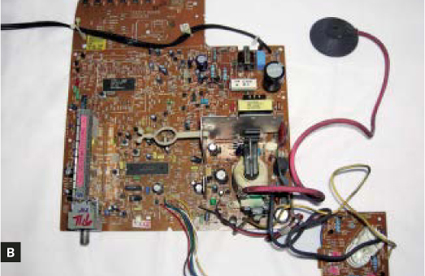
Fig. B: Circuit boards snapped out of the opened television without any unscrewing.

Fig. C: Colpitts oscillator circuit uses TV components to generate a sine wave you use as a broadcast carrier.

Fig. D: The flyback transformer, which pulls the tube’s beam along its scan pattern, has lots of winding wire.
The PC boards yielded far more parts than I expected. There were only 3 proprietary integrated circuits; the rest of the circuitry was all discrete, standard components. At the time of this set’s design, surface-mount technology had not yet kicked into high gear, so all the parts are easily usable for hobby projects, except fora few large SMT resistors.
I found 18 BC548 (2N2222) and BC558 (2N3906) transistors; both are commonly used in simple oscillators and transmitters. I also found 15 diodes and half a dozen semiconductor components of other types, plus an array of ¼-watt resistors, and ceramic disk and electrolytic capacitors. The RF chokes and slug-tuned inductors showed promise for future experiments, as did the infrared sensor for the remote control.
The power supply circuit included a mains-to-12V transformer and a pair of heavy-duty voltage regulators, and the flyback transformer on the back of the picture tube had lots of wire the perfect size for winding RF coils.
There was one great prize for any radio hobbyist, a “color burst” crystal with a frequency of 3.579MHz, which lies in the CW (continuous wave, used for Morse code) portion of the 80-meter ham band. There were also 4MHz and 8MHz crystals that have potential for other projects.
Using just the parts from this TV, there are many designs for radio transmitters you could build. One example is based on a Colpitts oscillator, which uses two BC548 (2N2222) transistors, a color burst crystal, and some resistors and capacitors. Add a Morse code key or other momentary switch at the oscillator’s power point and a ¼-wavelength stretch of wire at the antenna point (65’ 3" for a 3.579MHz signal), and you have a low-power radiotelegraphy station that will broadcast your dot-dash signals 25 miles or more, depending on conditions. Just remember to get your amateur radio license before you press the key down.
T.J. “Skip” Arey N2EI has been a freelance writer in the radio/electronics hobby world for over 25 years and is the author of Radio Monitoring: A How To Guide.