In our endeavor to create the Agnostic Composition Controller using probably the most popular SOA pattern, we demonstrated the role of two out of three core SOA operational frameworks, covering Service Creation, Composition, and Governance patterns. Focusing on its most complex realization, based on dynamic service discovery and invocation, we delved into the problem of Metadata Centralization and its relation to message structure and service layering: logical and physical; we cannot disregard these any longer. Building a Service Inventory without a plan in mind will produce results far worse than point-to-point spaghetti. Unfortunately, there is no tool to guide us right after the installation. Only the SOA principles (yes, to a meaningful extent) help us build a practical SOA inventory with a working Governance Reference model.
This chapter is the focal point of this book. First, we will give you a vendor-neutral taxonomy for a Service Inventory you can use with any tool without significant investments. Second, we will see how to roll it up to the Oracle Enterprise Repository and Service Registry. The Foundational Inventory pattern, together with the Inventory Implementation and Governance patterns, is the biggest category in the SOA patterns catalogue and covers all the aspects of a service lifecycle. We will try to cover all these aspects—from requirement analysis, service design, testing, and runtime monitoring to decommissioning.
Taxonomy is a method used to classify entities, items, and categories, among other things. The ultimate goal of taxonomy is to establish a hierarchy or structure of categories (in our case, all SOA artifacts). In this sense, an ontology is a wider concept because it is primarily responsible for the identification, separation, and description of categories, and it is further used in our classification to establish relations. Ontology is closer to the theory of classification, originally defined by Aristotle as the first philosophy. Recall that that's where we started in the first chapter—the identification of frameworks, principles, and characteristics essential for our service-oriented architecture. Finally, we put them together and declared relations and dependencies.
Now, we extend this initial hierarchy with the essential SOA elements to maintain optimal composability as an immediate target and promote effective SOA Governance. The outcome will lay a strong foundation for the entire Enterprise SOA Governance from all standpoints—software architecture, business, and operations.
Actually, we should start the book with this chapter, and only after establishing a solid foundation should we proceed with the on-top frameworks. The deceiving simplicity of WSDL-based service creation plays poor tricks on SOA-like projects, focusing only on the API aspects of service orientation. The blueprint of the Service Repository is a fundamental element of the Enterprise SOA architecture that demands commitment on all levels, primarily from architects. Surprisingly, not all architects are willing to support this architectural layer due to its complex nature and the fact that the direct benefits don't seem all that obvious. "We will think about it tomorrow. Today we stay on target—our delivery deadline." For this kind of attitude (read: project delivery mode from the initial example of Chapter 1, SOA Ecosystem – Interconnected Principles, Patterns, and Frameworks), architects are not required. If one does not know to which port one is sailing, no wind is favorable. The orchestration layer and ESB are not directions, but merely physical containers for our Service Inventory. These containers have been packed mindlessly by different teams working in parallel with a different understanding of service orientation, and will need total refurbishing every four or five years.
Think of it this way—your SOA Enterprise architecture is a megalopolis, inhabited by doctors, milkmen, truck drivers, firefighters, and so on. They are your service providers and consumers. To operate smoothly, they need to be positioned rationally (logical layering), that is, a fire brigade will serve no good if it cannot reach a certain location in the predefined time (runtime interoperability). Any good citizen should be capable of locating a (legally) required service with minimal effort, for example, by browsing the yellow pages (runtime Discoverability on the Service Registry). Most importantly, a citizen must be able to understand the nature of the service—look for a particular doctor, select the right one, and be sure that this doctor is located exactly where mentioned (interpretability of the Service Registry). These are our runtime features of the Service Inventory.
At the same time, you, as the good governor of this megalopolis, must plan the layering wisely—concentrate on one type of service, such as financial institutions (Inventory Centralization), and evenly spread another, such as waste removal and law enforcement (the Cross-Domain Utility Layer). To do so properly, you need a wide variety of information about these services (service records about your law enforcement officers), available in the Service Repository. Only a precise subset of this information will be used during runtime by other services. Some other types of service records will be constantly used to measure their (services) runtime behavior, and based on that, we will decide about service promotion or decommission. These are the design-time features of the Service Inventory.
Is the city too big for you to handle (Enterprise Inventory)? Don't take it personally. There could be many reasons, and most of them are out of your control—you are an architect and not a CEO after all. Start with one district (Domain Inventory) and constantly prepare for expansion. However, remember that neglecting even one of the patterns (presented in bold earlier in this section) will cause significant trouble in your domain. Thus, ideally, this chapter should have been at the beginning.
Nevertheless, nothing can prevent experienced architects from reading this chapter first. If you've played enough with ESB and BPEL and are now looking to get things organized, you know by now the principles to enforce and the gaps to fill.
However, the objectives we chase by implementing the Service Repository and the design rules we will implement to achieve these objectives (utilities) remain worth highlighting.
All presented ilities and related design rules are equally important and will have a proportional impact on the Service Inventory. However, the money is in the Discoverability principle (presented in bold in the preceding table). If we are unable to discover the required service or artifact, or understand what we have discovered, our SOA composability is worth nothing, literally. The situation would be even more dramatic if you were running a public service on a pay-per-use (PPU) basis, locally or on a cloud.
Furthermore, the Service Repository design will be based on the requirements of the already redesigned cross-Latin-American realization of the TM Forum's resource provisioning component:
- A composition of three provisioning BPEL flows with Pan-American content, which are agnostic to any CTU's geographical unit (GU) while handling an order header and body.
- The individual handler of an order line, although it is not agnostic and caters to specific parts of the operating countries.
- Other conditions must be taken into account. Every order line could spawn several subsequent processes depending on the mentioned conditions. These conditions are met by establishing a universal agnostic composition controller in the form of synchronous (OSB) and asynchronous (SCA) Service Brokers, as explained in the previous two chapters. They are the main service consumers of the Inventory Endpoint. They decouple the Service Inventory from other services and provide the lookup capability for all sorts of service artifacts.
Generally, we can expect three kinds of compositions or individual services to call the Inventory Endpoint:
- Compositions that are completely generic and potentially reusable on every geographic unit of operation. The roles can be Controllers, Subcontrollers, Initiators, and Composition members.
- Services that have a generic structure but different Endpoints or Endpoint particulars. The roles can be Controllers, Subcontrollers, and Mediators.
- Processes/services that are non-agnostic and GU-specific.
Regarding the first two, if we follow the SOA design rules, we will also have to make them domain-agnostic so that they are not just bound to the order-provisioning domain, but are much wider than that.
Our Assumptions for the technical realization are obvious, as follows:
- The SCA (BPEL) will be the main orchestration platform for long-running processes (already assumed and implemented).
- ESB will be the main Service Broker for short-running stateless operations (done in the previous chapter).
- Our design must be vendor-independent such that we can replace any component—stateless or common—by using custom build (Java) or other vendor components from other vendors.
The last assumption is extremely important for the Service Inventory and is the focal point in the entire service infrastructure—any inaccuracy in the implementation of the Service Metadata Centralization pattern will cause all other components to be severely affected, Discoverability to be compromised, and composability to become questionable.
In the previous CTU composition controllers' refactoring examples, two teams were tasked to maintain, lookup, retrieve, and inject service metadata into a service message in a form suitable for processing by at least two core players of our service composition:
- Composition Controller and Subcontroller (sync and async Service Brokers (SB))
- Adapter Factory (AF; also known as Generic Adapter (GA))
Both teams followed the same classification approach as follows:
- A single service's invocation is a task
- Each invocation has a number of particulars, expressed as parameters, bound to the task
- Composition is a sequence of the tasks that logically represents the business process or its completed part (scope is defined in BPEL terms)
Tasks can be grouped according to the business logic, but both teams must abide by the following rules:
- Do not make the routing slip (the task's execution plan) too complex
- If we have several logical groups (
>3) or too many tasks in a group (>9), then it is better to denormalize some processes again into an atomic task-orchestrated service and call it dynamically from a smaller execution plan
We are reiterating this only because we want to remind you that we are not reinventing the BPEL. We are purely centralizing the service metadata and applying it to the service message when necessary. So, the general structure is obvious: metadata elements should cover all composition levels (process, individual composition, task, and task parameters), but how different can the understanding of metadata be? The composition's Execution Plan for the custom synchronous Service Broker from the previous chapter is easier as we do not have to focus on the actions on the return path. So, let's look at it now. The following is just a single task node:
<TPProcess>
  <TradingPartnerProcessList EdiProcessId="100" EdiProcessCommType="6"
              BusinessEventName="com.ctu.oebs.purchaseorder.insert"
              Rule="1" RuleCondition="ALL" Source="OEBS"
              ObjectClassName="PurchaseOrder"
              ObjectName="PurchaseOrderID" ObjectAction="Insert"
              EdiProcessAckID="2" EdiProcessAckComm="6"
              EdiProcessReportLevel="3">
  <TradingPartners>
  <Senders>
 <Sender>
      <TPId>1</TPId>
      <TPCode>CTU</TPCode>
      <XDIBoxId>1</XDIBoxId>
         …
      <MailBox/>
    </Sender>
  </Senders>
  <Receivers>
    <Receiver>
      <TPId>2</TPId>
      <TPCode>IBX</TPCode>
      <XDIBoxId>2</XDIBoxId>
    </Receiver>
  </Receivers>
  </TradingPartners>
<TPProcessDescription>
      <TPProcessTask TaskId="1" ProcessTaskDescription="Receive"
            ProcessTaskId="1" ProcessTaskName="Receive"
            ProcessTaskOrder="1"
            TaskActionName="Receive"
            TaskDescription="Receive and Detect" TaskCommType="NA"
            TaskActive="Y" TaskParametersCount="1"
            TaskEngine="XDIMB.Pojo" ProcDefId="100"
            ProcDefDescription="TDC IBX PO" ReceiverEndpoint=""
            ReceiverEndpointHost="//somehost" ReceiverEndpointPort="3201"
            ReceiverEndpointUserName="" ReceiverEndpointPrivateKey=""
            SenderEndpoint="/Box/System/Out/" MsgId="83"
            MsgFileName="PurchaseOrder" MsgFileExt="xml"
            MsgLogLevel="3" MsgDescription="PurchaseOrder"
            MsgConsolidatedFlag="N" MsgGroup="Order" MsgCode=""
            MsgHeaderVersion="" SchemaFilename="" StylesheetLocation=""
            FieldSeparator="" ElementSeparator="" TermSeparator=""
            MsgHeader="" MsgFooter=""/>
      <TPProcessTask TaskId="2" ProcessTaskDescription="Translate"
    …
</TPProcessDescription>
</TPProcess>
Horrible, isn't it? However, we will not discuss the pros and cons of putting task parameters into the XMLNode attributes or present them as elements to parse/traverse simplicity. Also, incompliance with the XML elements' naming standard is not a huge crime, although it should be avoided. What you clearly see from this example is that the attempt to devise an all-occasion task with all the possible parameters leads to a mess. We got everything here: a path to transformation XSLTs (transformation task), delimiters and terminators for the EDI file translation (translation task), service engine descriptors for non-WS tasks, a process-logging level flag, a task-logging level flag, and so on. Truly, when you start expanding the parameter list, it's really hard to stop.
We need some guidance here to find a way to classify our major SOA artifacts and service particulars and rationalize their storage and extraction. Designing it as vendor-independent will eventually show us how this can be deployed on Oracle tools: Repository and Registry. Therefore, let's prepare the playground by installing Repository first. The taxonomy provided by Registry is UDDI based, so we will return to it a bit later in this chapter.
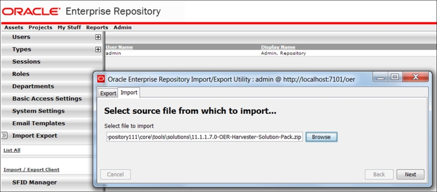
The Repository installation is straightforward (three simple steps). The installation instructions are easily found on the Oracle site. Nevertheless, we should mention a few things here. First, it's DB based, which is a positive feature because we want to change from the initial file-based design (although MDS can also be DB-based); however, this also means that close DBA attention will be necessary for this critical component (RMAN, RAC planning, and so on). You will create three tablespaces for data, indexes, and CLOB; please place them wisely. The application is a JAR file and will be deployed on your WLS, so the app server is the second prerequisite for the actual installation. Of course, OER can be installed not just on WLS (please see the complete list in the installation guide). Actually, the same is valid for DB as well. During the installation, please give special attention to the correctness of the value you put in the Fully qualified server name field (in local test mode, it's just a localhost). A typical .jar installation has a script screen identical to that in the following figure.
By the way, if something went wrong and you had to restart the installation, please do not forget to recreate the tablespaces (the installation will not continue with the tables in place) and purge the OER instance from the Oracle_Home inventory. It would be logical to create a new WSL domain (oer_domain) separated from soa_ and osb_. Do not forget to add an admin server with the console as a feature. Start it in the regular fashion (first is the Node Manager and then WLS, followed by the WLS console, start oer_server1) and log in to http://<localhost>:7101/oer/ using the default credentials. We will not tell you which ones.
At the time of writing this, it was admin/admin. Yes, have fun with Oracle password consistency. You will be prompted to change the password anyway. For further references, please go to the folder [Oracle_Home]
epository[xxx]core oolssolutions; the folder has some utilities essential for further SOA Governance:
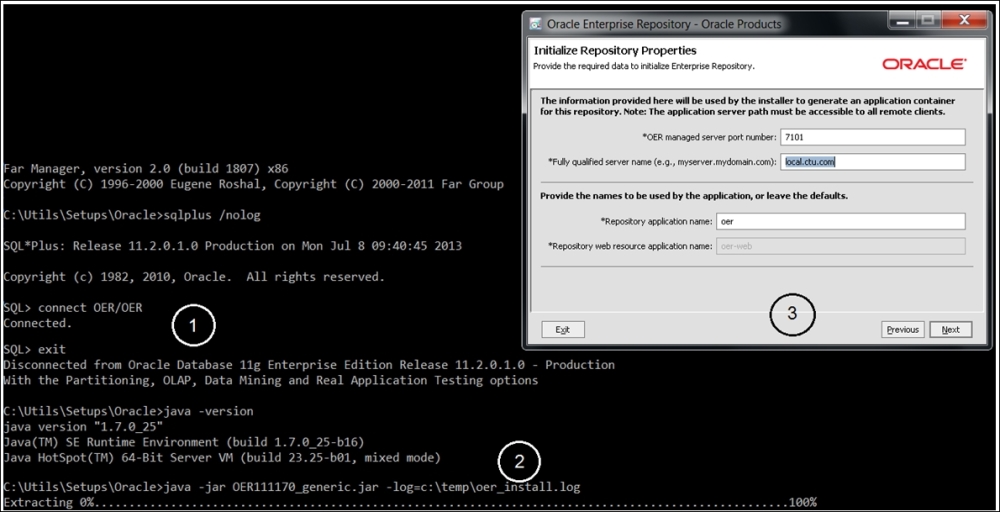
Oracle Enterprise Repository installation
Now let's check what we have got right out of the box in terms of taxonomy and SAO mindset organization. Since any Repository is initially organized around Asset Management as Asset is the main atomic unit of operational handling, search for All Assets of All Types and take a look at the list. There are several samples of varying types—from the adapters to the frameworks. You can explore relations between assets by choosing Asset and clicking on the left button below the Assets list. Technology adapters will be presented with no relations, and application adapters will be linked to the isolated application (such as Siebel). Guess what you will see once you have selected the MVC pattern?
You will see an Asset registration and the means to visualize the dependency, but we still need to maintain the categories, types, and relations; some SOA guidance would be useful here. Click on the Admin menu option and search for Asset Type to see what kinds are available (see the following figure):
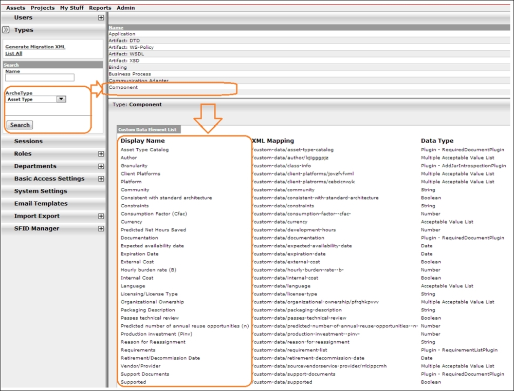
OER Asset Management
The more interesting type is Component; it is possibly one of the building blocks of our SOA, but what we have got in the default data element list for this type is not exactly encouraging. Hourly burden rate, License Type, and all other elements are certainly useful for runtime auditing and project management organization (they are also based on Enterprise Repository; we will come to that later in this section). However, we see only a couple of elements we could use for our runtime discovery in the Composition Controller.
No problem; no one expects a complete runtime-ready taxonomy model immediately out of the box. We have been following the SOA methodology all the way in the last two chapters, so we can try to export all our previously built artifacts and see how they will fit the existing taxonomy skeleton and what kind of categorization and types will be added to the classification.
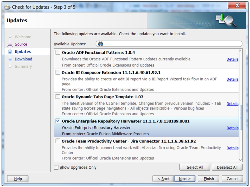
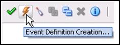
Before we proceed with the OER console, please complete one more install; this one will now be on your JDeveloper. Go to the update center and install the Enterprise Repository Harvester (see the previous figure). You will have to restart JDeveloper after completing the updates. Actually, the harvesting can be seen as an Ant task in JDev (we have other options as well), so we need to perform three more steps (for JDeveloper11g):
- Create backups of all your JDeveloper config files.
- Go to the
[JDev_home]/harvesterfolder created during the first step and replace all the occurrences ofC:/oracle/middleware/jdev_5361/jdeveloperintools11g.xmlwith your current JDev path. - Merge the content of your
tools11g.xmlwithproduct-preferences.xmlin your<user>/AppData/…/JDeveloper/<system_version>/o.jdeveloper(mine is inUsersspopovAppDataRoamingJDevelopersystem11.1.1.6.38.61.92o.jdeveloper). Copy the content if the XML hash nodeoracle.ideimpl.externaltools.ExternalToolListdoes not exist. Otherwise, simply replace it. - Check the OER connection detail in
[JDev_home]/harvester /HarvesterSettings.xml. You can also establish a connection by navigating to JDeveloper File | New | Connections | OER Connection, but after that, encrypting the password would be a good idea. Just runencrypt.batfrom the same folder.
The integration of OER and JDeveloper is one of the really effective OFM features, and we are sure that you will enjoy it. However, balancing it with one friendly warning would be in order.
Tip
To browse the Repository, any browser will do, but for administrative and maintenance features in Asset Editor, please use Internet Explorer with the latest JDK (see the installation screen); otherwise, there is a high probability that you will get the Premature end of file error. Quite annoying, actually.
Now, since we are forewarned, we can go back to the OER console and complete the second part of the harvester's installation. We need to import the harvester solution pack with all the possible service taxonomy types and classifications. Click on Admin and then Import/Export and import the pack as shown in the following screenshot:
When the import initiates, you will immediately notice the number of asset and relation types being imported (please see the following figure):
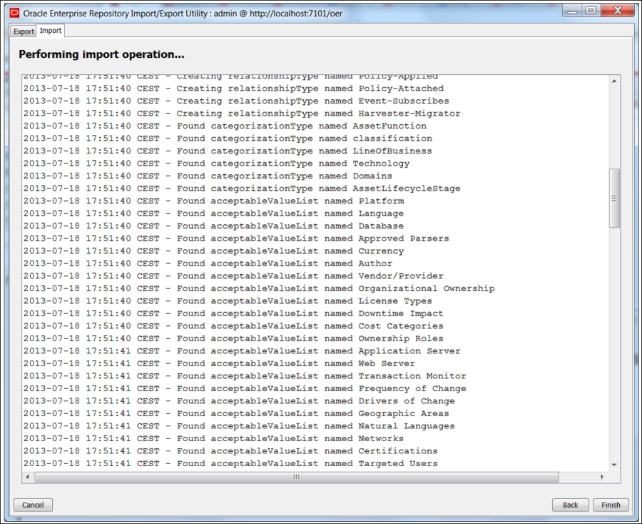
After completing the import, you can go to the Admin page and check the assets types again. We have got plenty of new artifacts and business processes, but the elements for the existing ones haven't changed; check this using the same Component asset. You will always see the recent changes of the Assets structure or their usage on the first page. How to change the types and elements for the assets including the element relations we will see a bit later, when we get a better understanding of what we want. At the moment, all these assets will be needed for harvesting, that is, uploading previously-built SOA components into a Repository.
Now back to JDeveloper. You will be able to see the following two options by right-clicking, as shown in the figure that follows:
- Submit Project to Enterprise Repository
- Submit File to Enterprise Repository
The first one can be applied to the root (your project's name) and the second is suitable for artifacts such as WSDL and XSD (2). Before you continue, please check the connectivity to the OER (1). It's right above the MDS connection we used in the previous chapters:
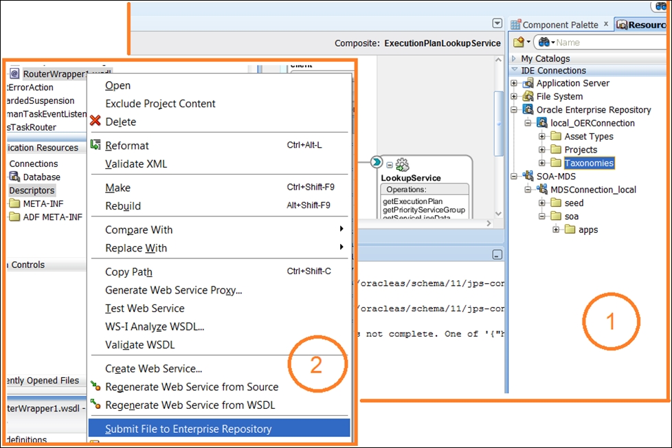
Submitting artifacts to Oracle Enterprise Repository
We will harvest the entire ExecutionPlanLookupService project; please see the Ant log in the following screenshot:
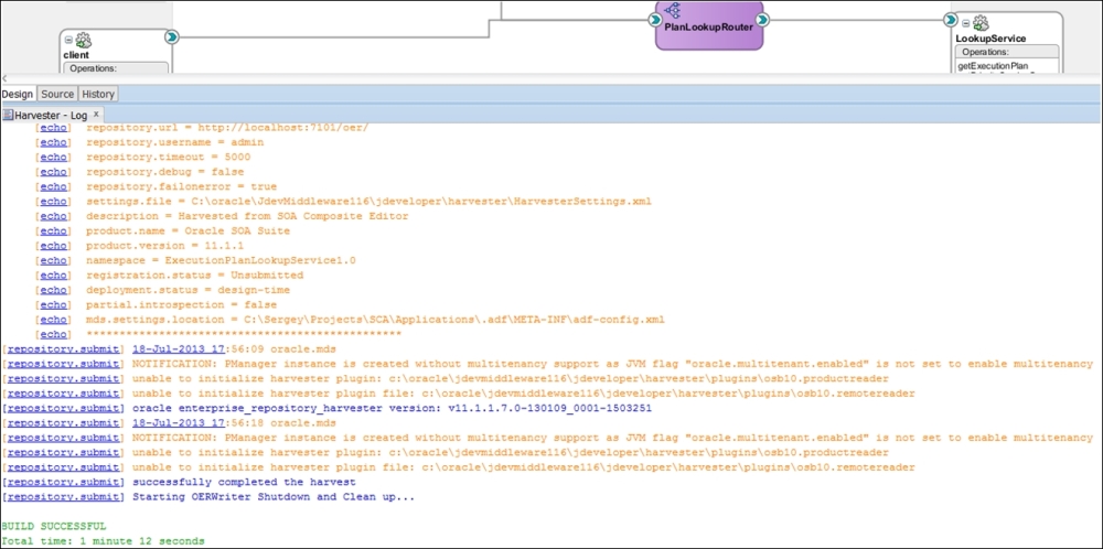
Harvesting SOA artifacts from the existing project
Although we successfully completed the harvest, some messages should attract your attention. We extracted all project objects and artifacts from the SOA Suite, but we have a lot references to OSB. So what about them? Oracle provided an individual harvester with OSB, which we can use for ESB object retrospection. We already have our OER prepared and the OSB configuration steps are similar to what we did in JDeveloper: modify HarvesterSettings.xml in the [MIDDLEWARE_HOME]<Oracle_OSB1>harvester folder, and set the correct OER connection parameters and path to our OSB project's export sbconfig.jar file. After that, encrypt the password. Now, to perform harvesting, run setenv.bat from the same folder and then osb11g-harvest.bat. You will see the OSB assets in the OER console by searching for the name of our project (for instance, we used Service Broker in the previous chapter). The Oracle documentation provides a complete reference to harvest in different runtime and design-time environments (http://docs.oracle.com/cd/E23943_01/admin.1111/e16580/harvest.htm). We suggest that you look closely at the relations between different assets harvested on different platforms.
So far so good. We have established a complete platform for bottom-up project development. However, browsing through the Assets Types, all we can see are collections of name-value pairs with basic relations, covering the generic needs of any Enterprise; these collections are not exactly SOA-oriented.
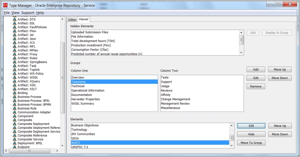
OER Type Manager's Taxonomies
The taxonomy of elements, presented for the service asset in the earlier figure, is too generic. Moreover, although it is suitable for dynamic invocation (Technical/UDDI registry), it still does not comply with all the requirements we expressed earlier for implementation using the Agnostic Composition Controller's capabilities.
Taxonomies such as NAICS and UNSPSC, mentioned in the preceding screenshot, are purely business-oriented and are not suitable for SOA as an architectural approach. To find the proper classification for service attributes, we should look at the public SOA taxonomies and ontologies.
Generally, we have two sets of public standards: Repository and Registry. Open Group came up with a wide range of standardization initiatives, of which two can be very beneficial to us:
- The SOA Governance Technical Standard (including the SOA Governance Reference Model (SGRM))
- The SOA Ontology Technical Standard
The Governance Reference model covers all aspects of the Enterprise SOA lifecycle and, naturally, all ontology features. One of the aspects covered is service harvesting, which is the third principle after service reuse and service description. We learned that it will give us little without the first two principles. Therefore, service metadata is the main element of the service description to support service reuse, one of the main SOA principles to maintain. There is a plethora of material on the SGRM standard for organizing projects, implementing change requests, and establishing and monitoring KPIs. However, in the context of this chapter, references to ontology are most important to us. A detailed presentation of the current version of Open Group's service ontology is provided on the organization's website, and we recommend that you take a close look at the two main diagrams on the introduction page, the ER diagram and hierarchy drawing—the entire ontology is graphically presented in these two forms. They are definitely something we could use for our OER taxonomy design, so review the diagrams intently.
Tip
Remember that these public standards are constantly under development. Conduct your own Web Ontology Language (OWL) studies (http://www.opengroup.org/soa/ontology/20101021/soa.owl) at the moment of publication.
When studying the hierarchy, we cannot help but notice several aspects that might be crucial to the acceptance of this ontology as the basis for agnostic composition controller implementation:
- On the SGRM page, the first guiding principle is "SOA Governance must promote the alignment of business and IT". This is effective indeed and has always been one of the goals (an objective, not a principle) of SOA. Please look at Chapter 1, SOA Ecosystem – Interconnected Principles, Patterns, and Frameworks, again in which we discussed principles, goals, good wishes, common sense, and what separates them. Nevertheless, this statement rightfully promotes Process as the key element of any business-oriented SOA. However, this is not the case when you look at the hierarchy graphics; Process is a child node in the Composition.
Generally, a top-level Composition consists of Processes and presents the Master Composition, not the other way around. On the other hand, in the OWL schema, the Process consists of Compositions. At the same time,
ServiceCompositionis a subset of the Composition and has no direct relation to the Service itself. We agree that a Process, Composition, andServiceCompositioncan (or cannot) be presented as a Service. However, in this case, a Service should be taken out of the hierarchy and placed separately, close to the Event. - The
ServiceContractandServiceInterfaceclasses are separate elements of hierarchy, and this could create some confusion. Generally, Open Group describes a contract in terms of SLA, which includes parties involved in service activities and their legal obligations.ServiceInterfacehas a more technical nature and presents an RPC-like access point for message-based invocations (not a totally correct term as we have DOC-type services, not RPC-style ones; however, we hope that you get the idea). Therefore, we can expect some attributes asOperationorTask(again, in WSDL terms). Indeed,Taskis the property of theServiceInterfaceclass. At the same time, you will find this property in theServiceContractclass. An example of theTaskproperty is provided by OWL: "WashWindowsis an instance ofTask, performed by the service provider (John)." - In addition to
Task, both contract and interface have something called Effect. Effect represents the outcome of service interaction and holds value for the customer. Here, we have another inconsistency. If our interface is message-oriented and a message is a transportable form of an object, then the logical outcome of the service operation is a new (changed) state of the object. An object's noticeable change is an Event—"The weather has changed. Expect heavy rain in ... hours." So, what is the Event according to the Open Group ontology? - An Event is described as an occurrence on an Element to which an Element may choose to respond. From this, we understand that an Element is, in fact, an Object. An Element is at the top of practically any hierarchy. You will find an Element at the top of the Open Group Ontology as well; only an Effect will be higher. An Event is detached and located at the bottom of the hierarchy. The logic underlying this decision is not entirely clear.
- The authors tried to avoid using the term "Object" and proposed a superclass for Element,
Thing. What's wrong with the old "Object" is completely unclear as well. - A Policy is defined as "a statement of direction that a human actor may intend to follow or may intend that another human actor should follow." First, when talking about SOA, we immediately exclude, during the functional decomposition phase, human operations from the composition logic, deeming them unsuitable for automation. We do not abandon them, but just have another approach for them. Thus, the policy should have a slightly broader meaning. Second, statements of directions are usually expressed through certain directives, that is, operations (tasks). These operations could be performed by units of logic without a contract or public interface (service agents, event-driven modules, not the services). Thus, the whole structure of the
Policyclass is rather questionable.
Despite these considerably small discrepancies with the classic OOP and generic SOA in terminology and relations ontology, we can take a lot from the presented approach and use it in our service metadata classification, optimized for dynamic and agnostic service invocation. We understand that the discussed ontology is an all-purpose model; therefore, we focus on relations suitable for practical implementation of Service Repository on traditional DBs.
Other standardization groups, excluding Open Group, have made proposals for the service metadata taxonomy. Noteworthy is the Reference Architecture Framework for the SOA (SOA-RA) initiative by OASIS (http://docs.oasis-open.org/soa-rm/soa-ra/v1.0/csd03/soa-ra-v1.0-csd03.pdf; please check for the latest release). At the time of writing, their draft seemed rather theoretical and the committee members were still debating on the definition of "service." When asked about the practical value of this reference model for SOA practitioners (at the fifth SOA & Cloud Symposium, where the first draft was presented), the presenter, Mr. Brown, responded that the purpose is to build a better SOA. Without a doubt it's a noble cause, and we believe that eventually it will produce something valuable for SOA practitioners. For now, taxonomy Elements such as Willingness, Social Structure, Evidence, Real-World Effect, and Reputation are out of the scope of the SOA patterns' implementation.
Actually, apart from the taxonomy, SOA-RA can be useful to understand the internal Oracle ER DB structure. As you already noticed, there are so many elements to maintain with so many relations in both public ontology frameworks that we couldn't avoid maintaining categorization using the name-value style. SOA-RA Elements Common to General Description (Figure 14 in http://docs.oasis-open.org/soa-rm/soa-ra/v1.0/soa-ra.pdf) is generic and quite similar to the asset definition domain in OER (please see the following diagram):
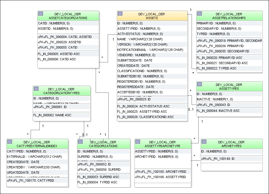
You can check it yourself, but just remember that the previously presented relational model from the real SR database is simplified for brevity. Nevertheless, using the model, you can easily construct the insert statement to manually insert assets. In addition to asset relations being constructed this way, the metadata domain also has a similar structure.
Tip
Another noteworthy, and rather important, point with regard to this type of DB model is that, although quite simple in design and, probably, in the initial value population, the key-value pair DB approach will most certainly turn into a nightmare from a maintenance standpoint later. Key-value pairs in relational databases are a constant headache for DBAs, SOA process owners, service custodians, and so on. Yes, the Oracle ER interface around this previous model will solve this problem gracefully, but the main issue will persist—the performance bottlenecks of your SQL statements during the runtime discovery on your Mediators and Service Brokers. And don't think of turning to the Big Data NoSQL model for this kind of metadata; this is not the case by any means. Quite soon, you will see that the taxonomy can be really lightweight and compatible with a relatively simple relational model.
In Chapter 1, SOA Ecosystem – Interconnected Principles, Patterns, and Frameworks, we mentioned another standard published by the HL7 group, called Service-Aware Interoperability Framework-Canonical Definition (SAIF CD). We kept this framework for the final discussion as we see it as an optimal model for lightweight repository implementation. Actually, it is not a single framework, it is an entire collection, covering Service Data Modeling, Governance, Enterprise Consistency, Conformity, and several others. Some of the frameworks (Governance) are completely based on the SOA concepts gathered in Thomas Erl's books. We will not repeat the concepts discussed in Chapter 1, SOA Ecosystem – Interconnected Principles, Patterns, and Frameworks. One framework is of particular value to us: the Behavioral framework; this provides the language necessary to explicitly and unambiguously define dynamic semantics used to specify the behavior of enterprise objects involved in shared purpose scenarios.
This is the core of the service metadata definition and classification, and it's attached from three directions:
- Contract semantics: In contract semantics, we can see only one unusual term, community, which represents the collection of interoperable objects aggregated by their business purpose or other similarities. The synonyms would be domain or group, but that's not as important. What's important is all relations between services, its possible roles and policies, and its permissions, prohibitions, and obligations are clearly and elegantly defined.
- Operation-specific semantics: This is even simpler and more straightforward, although the concept of an operation's pre- and post-conditions can be more clearly defined through policies (conditions apply to
ObjectContext) or other operations performed before or after. - Process semantics: This is probably the most complex in this framework, but we see a lot of similarities with our adoption of this concept, expressed by the execution plan object and Service Broker. The approach to the organization-specific implementation of SAIF-CD is basically derived from the SAIF Implementation Guide (IG).
Relations between these semantics and our implementation is presented in the following table:
|
SAIF BF process semantics |
SAIF description |
Oracle Composition framework |
|---|---|---|
|
Process |
Collection of invocations or operations |
Atomic task-orchestrated service (BPEL/SCA) or individual execution plan |
|
Flow elements |
Sequence of steps in a process |
BPEL Sequence or EP task group |
|
Activity |
Service operation |
EP individual task: |
|
Event |
Trigger |
 |
|
Sequence flow |
Ordered sequence of actions |
Execution plan |
|
Gateway |
Control element that performs branching, forking, merging, and joining |
Mediator in the SCA Service Broker (Chapter 3, Building the Core – Enterprise Business Flows) Adapter factory with a generic adapter in the OSB Service Broker (Chapter 4, From Traditional Integration to Composition – Enterprise Business Services) |
As we can see from this reference table, SAIF-CD is pretty close to our understanding of the general service taxonomy. We will use the best of these three open frameworks to establish logically structured, universal, and most importantly, well-performing metadata storage for runtime and design-time discovery. One open standard remains, which is especially designed for runtime discovery; it's our "yellow" book, and we will look at it now.
In contrast to all the possible repository taxonomies and ontologies, Service Registry is very well standardized. UDDI was one of the cornerstones of contemporary SOA, and Oracle can offer the latest release compliant with Version 3 of the open standard. To understand this standard, we must take a look at the tModel concept (http://uddi.org/taxonomies/UDDI_CoreOther_tModels.htm) as the key aspect of UDDI organization.
In discussing the Open Group Ontology, we mentioned two entities that represent a service to consumers and other composition members: ServiceContract and ServiceInterface. We also mentioned that the definition of ServiceInterface is generic and needs more detail for practical implementation. So, now, we can formulate that tModel (the technical model) as a complex data type, used for defining and representing the interface of a service we are going to discover and invoke (dynamically in our composition controller). In the case of the web service, tModel will at least represent the Service's WSDL as the URL, its name, and the description text, which is sufficient for service discovery and interpretation. We recommend that you view OWL and tModel side by side:
|
OWL Service Interface |
UDDI tModel for Service Interface (org.uddi.api_v3.TModel) |
|---|---|
|
<owl:Class rdf:about="#ServiceInterface"> <owl:disjointWith> <owl:Class rdf:ID="Service"/> </owl:disjointWith> <owl:disjointWith> <owl:Class rdf:ID="ServiceContract"/> </owl:disjointWith> <owl:disjointWith> <owl:Class rdf:ID="Effect"/> </owl:disjointWith> <owl:disjointWith> <owl:Class rdf:ID="HumanActor"/> </owl:disjointWith> <owl:disjointWith> <owl:Class rdf:ID="Task"/> </owl:disjointWith> </owl:Class> |
<complexType name="tModel">
   <complexContent>
     <restriction base="{http://www.w3.org/2001/XMLSchema}anyType">
       <sequence>
         <element ref="{urn:uddi-org:api_v3}name"/>
         <element ref="{urn:uddi-org:api_v3}description" maxOccurs="unbounded" minOccurs="0"/>
         <element ref="{urn:uddi-org:api_v3}overviewDoc" maxOccurs="unbounded" minOccurs="0"/>
         <element ref="{urn:uddi-org:api_v3}identifierBag" minOccurs="0"/>
         <element ref="{urn:uddi-org:api_v3}categoryBag" minOccurs="0"/>
         <element ref="{http://www.w3.org/2000/09/xmldsig#}Signature" maxOccurs="unbounded" minOccurs="0"/>
       </sequence>
       <attribute name="tModelKey" type="{urn:uddi-org:api_v3}tModelKey" />
       <attribute name="deleted" type="{urn:uddi-org:api_v3}deleted" default="false" />
     </restriction>
   </complexContent>
</complexType> |
The simplest XML service descriptor based on the tModel's XSD from the preceding table will be as follows:
<tModel tModelKey="uuid:9AF82501-E6A9-1ba3-A094-2C7FE45CD859">
   <name>Public interface for adding NEW Mobile Service into clients Order bundle </name>
   <description xml:lang="en">WS Interface for addNew Mobile CTU generic Order</description>
   <overviewDoc>
      <description xml:lang="en">The service's WSDL document</description>
      <overviewURL>http://www.ctu.com/bss/ services/order/provisioning/
             /addMobileOrder.wsdl</overviewURL>
   </overviewDoc>
   ….
</tModel>
As you can see, this model is uniquely identified by UUID, used as a reference to this model. For the service's invocation, the most important element is overviewURL, containing the pointer to the service WSDL/Endpoint descriptor. All other elements are self-descriptive.
Rather minimalistic, isn't it? Generally, what we can get is the reference to WSDL and information about its structure (remember the discussions about abstract and concrete in Chapter 1, SOA Ecosystem – Interconnected Principles, Patterns, and Frameworks). We can figure out what a server does and what effects to expect. So, is UDDI just a list of WSDL? What if we need some more information about a service and, more importantly, not just as a consumer where just the Endpoint is enough, but as an Agnostic Composition Controller and/or Agnostic Adapter Factory? By the way, what if our service provider is not SOAP/WSDL-based at all?
Well, generally, we can put any type of Endpoint in the overviewURL element. All other service particulars can be packed in a bag. Literally, there is an element named categoryBag; please see its schema in the following code:
<complexType name="categoryBag">
   <complexContent>
     <restriction base="{http://www.w3.org/2001/XMLSchema}anyType">
       <choice>
         <sequence>
           <element ref="{urn:uddi-org:api_v3}keyedReference" maxOccurs="unbounded"/>
           <element ref="{urn:uddi-org:api_v3}keyedReferenceGroup" maxOccurs="unbounded" minOccurs="0"/>
         </sequence>
         <element ref="{urn:uddi-org:api_v3}keyedReferenceGroup" maxOccurs="unbounded"/>
       </choice>
     </restriction>
   </complexContent>
 </complexType
So, the XML portion of this bag will be in tModel as presented in the following code:
</overviewDoc>
…
<categoryBag>
      <keyedReference
         tModelKey="uuid: 9AF82521-F6A9-1ba3-C094-2C7FE45CD859"
         name="Another specification to web service or other endpoint descriptor"
         value="SomeWSDLSpec"/>
   </categoryBag>
</tModel>
But wait, can you figure out what the structure is? Yes, you're right, it's a name-value pair. What else could it be? There is no other way to define plural properties. By the way, the schema for identifierBag is similar, but a bit simpler. Thus, the categoryBag element is a collection of keyedReferences, where each of them is presented as a tModel. Therefore, you can have a collection of technical specs in the form of tModels to express different WS categories: messaging protocol, transport protocol, portType references, MEP types, and so on. Actually, mapping between WSDL and UDDI V2-V3 is pretty straightforward, and this fact raises a question: Why do we need a description for the description?
Well, individual services (for example, our milkman, postman, or doctor) could have a good description of their individual capabilities, but we need a structure to put all of them into our services' yellow book. Again, we have pretty good mechanisms to build this structure in the form of tModels, but we are (yet again) on our own in the quest of delivering it.
In the first chapter, we mentioned that our first attempt at establishing global service Discoverability was not a real success, and now you can see why. Initially, UDDI was not about web services, it was about business collaboration. tModels are just a way of describing entities and relations between them. The complete UDDI hierarchy consists of the following:
businessEntity: It's your company, or business unit, that provides a wide variety of business services, and thus the model should be descriptive enough: the company's name, description of the line of business, contact details, and available business services. Previously mentioned business taxonomies, such as NAICS and UNSPSC, are very well suited for the description of this entity and are widely used in theidentifierBagandcategoryBagreference collections (via tModels of course). In this case,identifierBaganswers the question "What is the company we are describing here?" andcategoryBagaddresses the questions "What are the functions of the company?" and "What are the services provided by the company?"businessService: The schema of this entity represents descriptive information about a particular family (or domain) of technical services. In addition to the name, the description, andcategoryBag, this has one or severalbindingTemplates, representing the technical description of publicly available services (as tModels of course).bindingTemplate: At the top, it has a human-readable description and theAccessPointelement holding the host URL. The URL type is provided as an attribute, such as an HTTP host. Detailed service info is gathered in thetModelInstanceDetails/tModelInstanceInfocollection.
With so much freedom provided by tModels and the lack of comprehendible taxonomies in the earlier 2000s, anarchy reigned in the SOA realm, quite severely damaging UDDI acceptance. With the new arrival of different API servers, we hope that UDDI will improve its reputation. It's still one of the existing strategic technologies shaping the SOA landscape, and Oracle plays its part quite well here.
To get a closer look at the tool, please proceed with the installation. It's quite similar to OER. Here, again, you should start with the DB preparation, although only one tablespace is necessary—the UDDI value-name pairs are quite light and do not require LOBs:
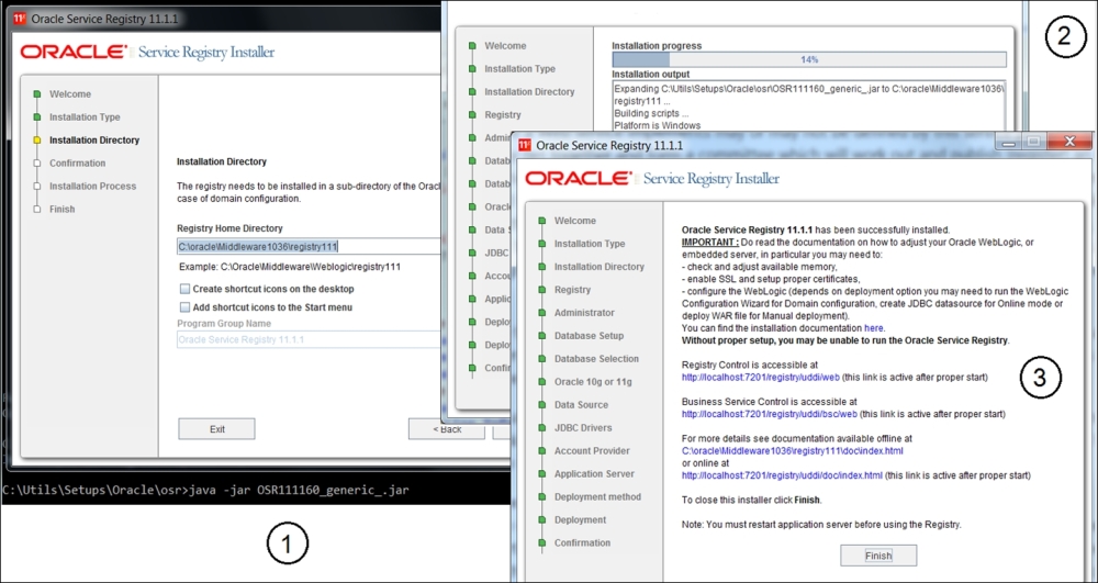
Oracle service Registry installation
The installation is simple, as shown in the preceding screenshot (steps 1, 2, and 3 for training purposes). You do not have to create a separate WLS domain and install it on the existing OER domain. Just assign a different port for the console (we use 7201 as you can see in the next screenshot, step 1). To get a better understanding of Oracle's approach to the tModels' implementation, include the demo data installation during the DB selection step. Upon browsing the DB schema, you will find that the internal DB tables' structure is clearly built around the UDDI taxonomy—there are dedicated tables for BusinessEntity, BusinessService, and BindingTemplate.
For each table, maintain separate bags for categories and identities containing references to tModels registered in the related table. Despite this model's simplicity, there are many additional service tables grouped in the service domains, as follows:
- Approval
- Access control
- Replication
- Events Reporting
This grouping should attract our attention as it has a direct relation with the physical realization of the SOA patterns and the Registry layering in particular. During the installation, you probably noticed that we can install the Registry in three different modes: Publication, Intermediate, and Discovery. This is how Oracle (quite cleverly) implements the double D in the UDDI standard. Naturally, as an architect, you will not allow anyone registering for new/updated services directly in your production registry. Initially, information should be injected into the Publishing registry (first D) and you can have as many as you need (per business domain, GU, or service roles). All these registries are stacked vertically, that is, they have the same rank. After approval, metadata will be propagated to the Discovery Registry (second D). You will find more details about the OSR data model/tModel relations and deployment topology in the Oracle documentation at http://docs.oracle.com/cd/E14571_01/doc.1111/e15867/uddi.htm.
Publishing service artifacts and taxonomy categories (see the following screenshot, part 2) using the UDDI console is straightforward. Just follow the screen instructions after clicking on the menu options at the top (for WSDL and other XML-based artifacts) or the tabs on the left for Details, Categories, and Identifiers (see the following screenshot, part 3) when modifying business entities or tModels.
According to the SOA Governance cycle, any artifact has to pass several approvals and be accepted by several custodians (for example, Service, XSD/Schema, and the Policy and Registry custodians). Thus, in addition to vertical layering, we will have a horizontal chain, presented by the intermediate registries between the publication and discovery.
It is wise to have individual Intermediate Registries in every individual test environment, JIT-UAT-ORT as well, and promote services to production only after passing all acceptance gates:
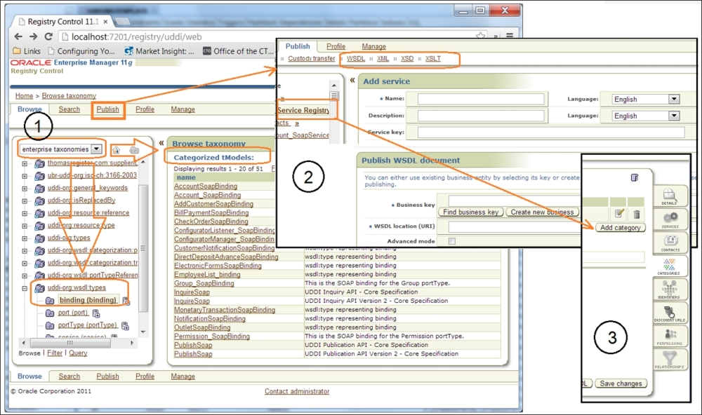
Publishing service artifacts on UDDI
Although Oracle provides a clear OSR installation guide, we would like to advise you to be careful with the node installation sequence for security reasons. Naturally, all centralized assets concentrated in the Registry are protected by security policies and ACLs. We recommend LDAP for the storage of user accounts, but trust the relations between registries in the propagation chain, maintained by digital security certificates. Therefore, we advise you to start from the end. The digital security certificate of the Discovery Registry is needed when installing the Publication Registry.
Another highly important SOA pattern must be strictly observed here due to the critical nature of the Registry and its position as the single point of failure: redundant implementation. In the WLS-based topology, we choose from the very beginning; it's attained by means of a WebLogic Cluster. The Cluster operation is achieved by running multiple registries and combining their functionalities with a load balancer (proxy). The configuration of this infrastructure is common for WLS and well documented in the HA section of the OSR installation guide.
As the central point of the Enterprise SOA, OSR has all the possible connections to the SOA Suite, Enterprise Repository, OSB, and development environments (JDeveloper). In the following screenshot, you can see how, in five easy steps, we can initiate the dynamic resolving of the WSDL Endpoint location using Oracle Registry in JDeveloper. First we establish the connection (File | New | Connections | UDDI Registry Connection) and then verify it in the JDev Resource palette. Now you will see the three connections ready and at your service (including OER and the old MDS):
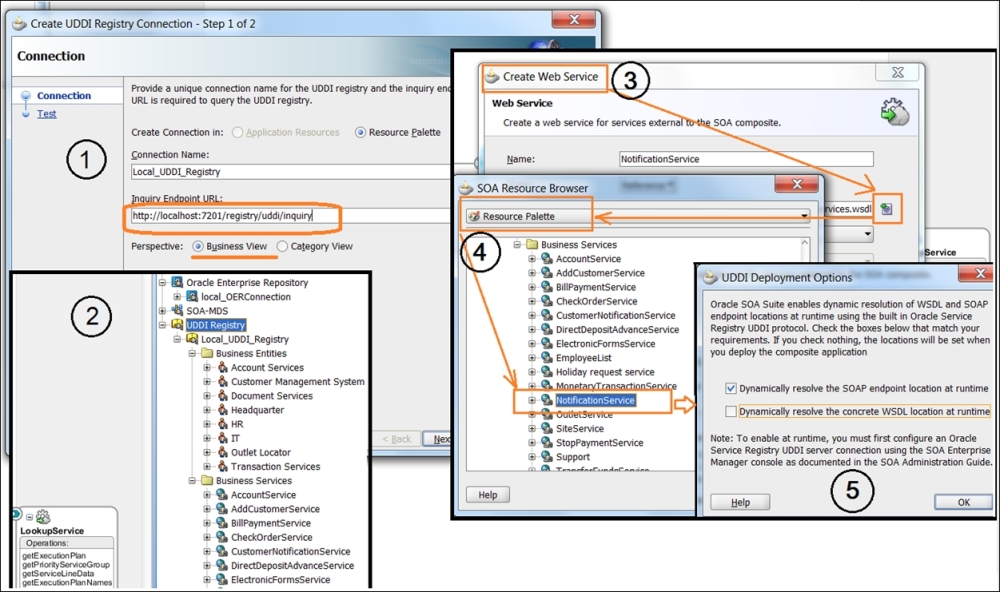
Configuring a service artifact's dynamic resolution
Drag a new web service to the right SCA swimlane and click on the icon for the WSDL selection; take it from the Resource palette and then select the earlier published (previous figure, step 2) service.
After that, you will be prompted to select a runtime dynamic resolution type (the SOAP Endpoint or WSDL), and that's the essence of our runtime Discoverability using UDDI! Depending on the selected UDDI deployment option, the composite.xml file will have a different syntax for the binding.ws element, describing the Endpoint's binding location.
|
Endpoint type |
Binding realization |
|---|---|
|
SOA Endpoint |
 <binding.ws port="http://ctu.com/wsdl/dev/uddi/services/#wsdl.endpoint(OrderStatusService/OrderStatusService)"
                location="http://localhost:7201/registry/uddi/doc/dev/OrderStatusService.wsdl"
                soapVersion="1.1">
      <property name="oracle.soa.uddi.serviceKey" type="xs:string"  many="false">
                                            uddi: 9AF82521-F6A9-1ba3-C094-2C7FE45CD859
       </property>
    </binding.ws>
|
|
WSDL |
    <binding.ws port="http://ctu.com/fulfillment/order#wsdl.endpoint(OrderStatusService/OrderStatusService)"
                location="orauddi:/uddi: 9AF82521-F6A9-1ba3-C094-2C7FE45CD859"
                soapVersion="1.1">
    </binding.ws>
|
Now you can use any service with the dynamic address resolution in any service composition. This basic yellow book functionality is perfectly fine, but we need more search capabilities with adequate granularity for search criteria, which is suitable for our agnostic controller. Here, we face the second type of limitation (apart from the lack of taxonomy guidance, which is mostly based on the WSDL binding)—limited search capability. In general, the classic UDDI provides us with search restricted to the WS name and its classification. Because of the name-value pair approach of the tModels, there is no uniform way to query services and their attributes. Some attempts were undertaken in the UDDI V.3 specs (see sections 4 and 5.1.8 of the Inquiry API functions, http://uddi.org/pubs/uddi-v3.0.2-20041019.htm#_Toc85908076). You will find 10 generic functions to find core UDDI entities (Business, Service, and Bindings) and get details about them, including tModels.
Oracle offers a solution for these limitations by providing the UDDI API, which covers both Ds—Description (Publishing API) and Discovery (Inquiry API). In the scope of dynamic composition controller functionalities, the latter is of higher interest to us. Technically, we have two Inquiry APIs: ClientSide and UI. The last one has only one operation, get_entityDetail, which will return the list of UDDI data structures. Using the ClientSide API, you can call any standard UDDI V2 inquiry function. The most commonly used parameters are Name (find_<searchingEntity>.setName(new Name(Name))), serviceKey (find_<searchingEntity>.serServiceKey(serviceKey))), and tModelKey (find__<searchingEntity>. addTModelKey (tModelKey))). We can also define any String qualifier in our search, such as find_tModel.addFindQualifier(findQualifier), when preparing the find object. This gives us some freedom in defining our search criteria, but we must be certain about what we are looking for and the parameters available to define our search in the SBDH-compliant Message Header. These parameters are marked in bold in the full version of MessageHeader in the following code. So, some of them can be categorized as Service Entities, while most of them qualify as tModels for the taxonomy we are about to build:
<?xml version="1.0" encoding="UTF-8" ?>
<urn:CTUMessage xmlns:urn="urn:com:telco:ctu:la:ctumessage:v01"
                xmlns:urn1=" urn:com:telco:ctu:la:messageheader:v01"
                xmlns:urn2=" urn:com:telco:ctu:la:processheader:v01"
                xmlns:urn3=" urn:com:telco:ctu:la:payload:v01"
                xmlns:urn4=" urn:com:telco:ctu:la:messagetrackingdata:v01">
    <urn:MessageType>EBO</urn:MessageType>
    <urn:Version>0.1</urn:Version>
    <ns11:MessageHeader xmlns:ns11=" urn:com:telco:ctu:la:messageheader:v01">
        <ns11:RefId>604244_1</ns11:RefId>
        <ns11:RequestId>CMSA697</ns11:RequestId>
        <ns11:MsgId>EBM109</ns11:MsgId>
        <ns11:RefDateTime xsi:nil="true" xmlns:xsi="http://www.w3.org/2001/XMLSchema-instance"/>
        <ns11:Sender>
            <ns11:SenderCode xsi:nil="true" xmlns:xsi="http://www.w3.org/2001/XMLSchema-instance"/>
            <ns11:CountryCode>BR</ns11:CountryCode>
            <ns11:Affiliate xsi:nil="true" xmlns:xsi="http://www.w3.org/2001/XMLSchema-instance"/>
            <ns11:Instance>BR_IP</ns11:Instance>
        </ns11:Sender>
        <ns11:ObjectReference>
            <ns11:ObjectName>Order</ns11:ObjectName>
            <ns11:ObjectKeyName>OrderID</ns11:ObjectKeyName/>
            <ns11:ObjectKeyData> CMSA-697BR09521</ns11:ObjectKeyData/>
            <ns11:Domain>Fulfillment</ns11:Domain>
        </ns11:ObjectReference>
        <ns11:ObjectContext>
            <ns11:ParameterValue name="ActionType">DROP</ns11:ParameterValue>
            <ns11:ParameterValue name="ProductType">IP</ns11:ParameterValue>
            <ns11:ParameterValue name="ServiceType">SERVICE</ns11:ParameterValue>
        </ns11:ObjectContext>
    </ns11:MessageHeader>
Now that we are equipped with the knowledge of OER and OSR functionalities and open SOA ontology standards, we will continue with the functional analysis of runtime Discoverability requirements for the composition controller.
We will start with the runtime Discoverability requirements because it seems a bit easier—we are already using runtime lookup for the service particulars and different XML artifacts in the EBF and EBS service composition controllers, and all requirements are expressed in the execution plan's structure (look at ExecutionPlanLookupService). This is our Service Registry and is currently based on MDS, but our intention is not to isolate Registry and Repository, but to rationally combine them into one management pack. In this respect, Oracle has two products to offer, OER and OSR, with a utility for the synchronization of metadata between them (orrxu, http://docs.oracle.com/cd/E21764_01/doc.1111/e16580/oereu.htm). Adding the metadata harvesting capability in OER for reverse engineering and the requirements for OSR integration with WLS for the automatic registeration of new service deployments in the Service Registry will complete the picture of Oracle's response to the Discoverability principle and SOA Governance.
But isn't it too complex? Yes, it is. The simple fact that the OER DB schema has 145 tables (Release 11.1.1.7.0) for "all weather conditions" doesn't make our life easier. From the very beginning, it was clear that managing complex technologies such as SOA would not be easy, but we should expect a bit more methodological support for SOA runtime compositions in particular. We are about to provide this support to the best of our ability, focusing on vendor-neutral SOA principles first and then extending them to Oracle's product realization (OSR and OER).
We will do this exactly how we did in the previous chapter: discuss a generic Message Broker requirement first and then implement it as a Service Broker on OSB. Speaking of which, we must mention certain things related to its complexity:
- Runtime and Design-time lookups are closely related and the physical segregation of Registry and Repository is not always optimal from a performance point of view in regards to the complexity of queries. Registry realization is UDDI compliant; thus, we will have three major XML data structures, presented in tModels. In general, it's a representation of service interfaces (for instance, WSDL for WS), and all other related extra features come in value-name pairs. It may be flexible (in terms of the value-name pairs), but not always interpretable and, therefore, discoverable.
- Continuing with a repository's segregation issues, we can say that simply mixing SOA project data, service design particulars, runtime logs, service session data, results from load/stress—only because they cannot be easily defined in the tModels taxonomy or are not related to the Registry—will definitely not improve our SOA Governance (see a single schema of OER). Keeping the Governance under control, we can clearly identify the boundaries of
AuditLogs,ErrorLogs, project control data, and the Service Repository itself. This consideration requires a precise definition of Inventory Endpoints' interface(s), suitable for all types of Governance actions. - To continue with Governance, a services metadata harvesting tool is a really effective feature. However, ask yourself: if you, as an architect, have been devising an enterprise Service Inventory for a while now and still need to perform reverse engineering to reveal hidden dependencies, then how valid is your service taxonomy? Could it be that you overlooked some services/entities during the design phase? No, we are not saying that a harvester is unnecessary; that's not the point. Indeed, you should run it regularly (it's an Ant task in JDeveloper), and if in OER Asset Editor's search report you see anything new or something that you haven't seen in the
Unsubmitted/Unfilledfolder, you can proudly ask for a raise. - Whatever technical realization you choose for our Service Inventory (building blocks such as services or components; languages such as Java, C, PL, and SQL; and so on), your primary concern is the availability of your Service Registry/Repository for the flawless support of Discoverability, along with other utilities from the first table in this chapter. Please take a second look at the design rules in this table.
What would be the most logical approach to address availability and performance issues expressed in the preceding bullet points? Correct, to position SR as close to the composition controller as possible. But how would this be possible? Only by the segregation of the service taxonomy model from its physical realization. Doing so, we should be able to re-implement it on any technical platform, easily accessible by the concrete composition controller. Remember, Secure Gateway in DMZ is an ESB too, and Service Broker is common to both. Thus, service metadata lookup is not an extraordinary feature. Will you query your production OER or OSR from DMZ? Think twice. You could have the discovery node in DMZ, but what about the physical storage? Oracle DB? Again, think twice when it comes to security. You should be quite close to the iron. How will you securely synchronize your Production and DMZ discovery nodes?
One of the practical ways to classify services and artifacts' taxonomy is to detect the type of data we see on every service layer. For vertical infrastructure layering, we suggest that you use the Oracle AIA service layer notation. This leaves us with three main layers: Adapters, Enterprise Services (usually hosted or available through ESB), and task-orchestrated services in the Enterprise Business Flow layer. Note that vertical stratification for the three main service models still remains; vertical layering is presented in the following figure:
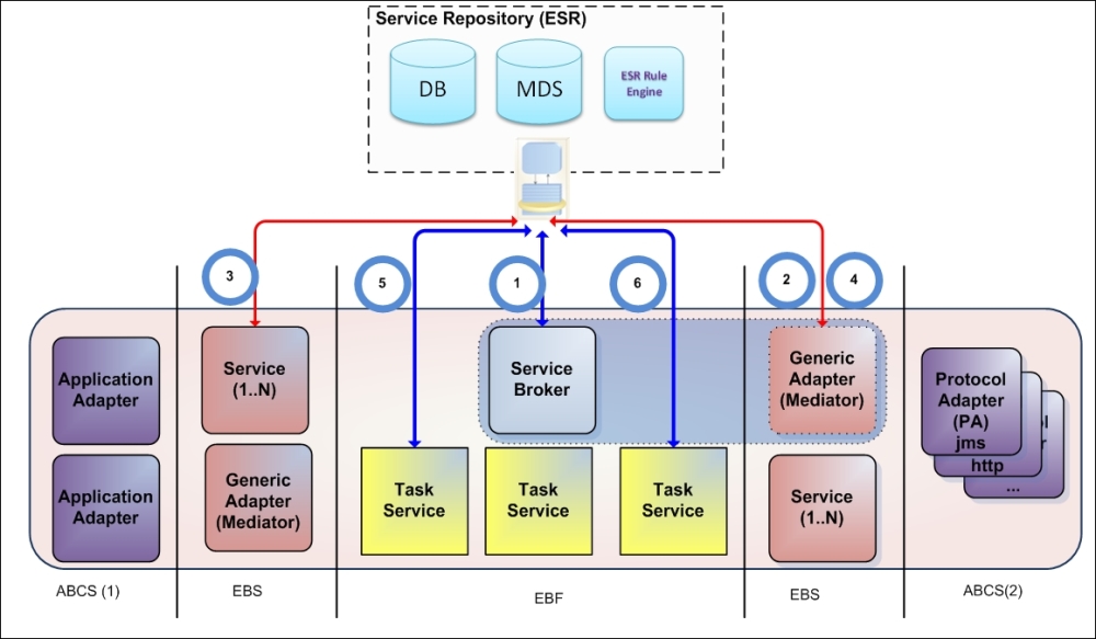
Based on the preceding figure, in the following table, we consolidated all the possible lookup and entity types that our Service Repository must maintain and reliably provide. The table has a numerical index for Lookup Types (runtime discovery use cases) for simple reference in this and further chapters.
Lookup type 1: The service business delegate is looking for a service worker:
|
Role |
Location |
Entity |
Example |
|---|---|---|---|
|
Composition controller / Composition subcontroller |
EBF, EBS |
Service as a URL, Component as a URL |
|
Lookup type 2: The service is looking for the Endpoint(s):
|
Role |
Location |
Entity |
Example |
|---|---|---|---|
|
Composition subcontroller, Dispatcher, and Mediator |
EBF, EBS |
The TP Endpoint URLs could be as follows: File, JMS, HTTP, and FTP |
|
Lookup type 3: The service wants to perform data transformation/validation:
|
Role |
Location |
Entity |
Example |
|---|---|---|---|
|
Dispatcher and Mediator |
EBS |
|
The ESB Service resolves parameters for transformation/Enrichment |
Lookup type 4: The service is looking for Endpoint particulars (bindingTemplate in the tModel notation):
|
Role |
Location |
Entity |
Example |
|---|---|---|---|
|
Dispatcher and Mediator |
EBS |
Object (EBO/SDO) |
ESB is looking for the Endpoints' particulars (Transport, Proxy, Port, and Username/Password). |
Lookup type 5: The service is looking for an internal task's parameters:
|
Role |
Location |
Entity |
Example |
|---|---|---|---|
|
Service participant |
EBF |
Object (EBO/EBM) |
|
Lookup type 6: The service is making a decision(s):
|
Role |
Location |
Entity |
Example |
|---|---|---|---|
|
Dispatcher, Mediator, Service-participant |
EBF, EBS |
Object (EBO/SDO), TP Endpoint URL |
|
Summarizing all the entity types from the preceding table, we come up with the six main types, which are in line with the public classifications proposed by Open Group and SAIF BF:
- Objects (top hierarchy entity).
- Messages or message particulars (XML or a representation of a serialized object in transit).
- Services, tasks, or a task's particulars (including WSDL and its parts).
- An application's Endpoints or Endpoint particulars (SOAP or other types).
- Rules or Rulesets.
- Enterprise Business Events.
The SR physical implementation can be as follows:
- File-based (for instance, temporarily MDS has been used in all previous chapters)
- DB-based (planned for flexibility and performance):
- The OER DB schema with complex assets relations
- The OSR entities with metadata elements in tModels
- Custom DB with OER/OSR synchronization (a custom DB structure is presented later in The SQL Implementation of the service taxonomy section in this chapter)
The composite entities (such as tasks) can be constructed as:
- Static from the file location
- Dynamic from the DB query
- Static from the DB
- Dynamic from the RE
A common rule for the ER implementation for all approaches is to have a unified ESR endpoint for an entity lookup, with the MessageHeader elements as an input parameter.
With entity types accounted for and identified, to save your time, we will jump right to their relations and explain their roles later:
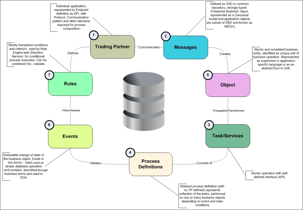
SR entity relationships
In the center, we have our Entity Repository storage that holds all the metadata in a secure, interpretable, and discoverable fashion. According to Conway's law (http://www.melconway.com/Home/Conways_Law.html), it can be organized in at least four different ways:
- Decentralized (project-based)
- Domain
- Cross-domain
- Enterprise
The idea of decentralized realization is to avoid lookups of any kind and maintain the orchestration logic as a static process. This way, processes will be reconfigured only through recoding and reimplementation. Simply put, this option can be described as do nothing. We identified all the downsides of this approach at the beginning of Chapter 3, Building the Core – Enterprise Business Flows, when discussing the assessment of the CTU SOA solutions.
The primary goal of this realization is to establish a centralized metadata repository for all artifacts developed within a single SOA project. This repository can support runtime lookups (for instance, in SCA Mediator), but for entities designed for a specific SCA, limited by a single project or a small group of projects. The structure of metadata, its taxonomy, and ontology will be completely at the discretion of project's team lead. You will certainly remember the small exercise from Chapter 4, From Traditional Integration to Composition – Enterprise Business Services, when we implemented a basic proxy on OSB. In the first step of this exercise, we created a common folder structure for XML-based artifacts. We realize that many of you found it far from optimal and different from your usual classification. This is exactly our point. A project-centric repository, based on a similar (custom) approach and maintained using Oracle Metadata Services (MDS), is extremely flexible and convenient for a single department; however, it requires constant vigilance from SOA architects and Governance specialists. In fact, as is, it fits most of the needs of a small department. The positive side is that the performance of the MDS lookups (for file- and DB-based MDS realization) is quite good. Based on the runtime lookup scenarios' individual tables from the preceding section, we can identify the lookup types and entities as follows:
- Lookups types in use: The types are none or limited, which use the oramds protocol
- Entities maintained: The entities are none and are project specific in MDS
The first approach in project-based SR realization is straightforward:
- The first and second assumptions (from the General objectives section) are taken for granted and the provisioning flow is functionally decomposed at the level where agnostic common services are separated from the functionally complete GU-specific business services.
As a result, the layers of the Service Inventory are established for the task and entity services.
- Design new, full-scale, functional compositions to minimize the creeping of business logic, that is, reduce the number of compositions for maintenance and reusability purposes. This is the classic top-down approach.
A top-down approach means to devise a complete analysis upfront. It does not just take a lot of time, but considering a dispersed GU, it requires deep and precise knowledge of the entire business operation everywhere, not to mention a substantial budget. In general, it is too late to conduct a top-down analysis at this stage, although the analysis itself is a positive practice.
- Use SCAs to implement compositions in a static BPEL way. Dynamic Service/Endpoint invocations with lookups, avoiding the creation of BPEL flows, are more visible when it comes to inexperienced developers.
The Utility Services layer in the Service Repository is deliberately neglected for the purpose of simplification. In fact, it can potentially lead to the implementation of hybrid services. In this case, reliability (Objective 1; the first objective from the objectives table at the beginning of this chapter) is reduced.
If vendors' SOA knowledge is deliberately not considered very high (for the man/hour cost reasons), it will broaden the choice of vendors; however, this potentially invites inexperienced solution providers and affects reliability.
In general, processes will be identical to minor alterations and developed using the copy and paste approach. Maintainability (Objective 3) will be severely affected. With no common Utility components as the single point of failure, reliability can be high. However, without design time discovery, after several implementation laps, it will be virtually impossible to maintain the desired level of reusability (Objective 2).
Reliability (Objective 1) can vary by process, depending on the complexity of the orchestration logic. The more complex the "if-else" logic used, the more prone to errors the process will be. As a workaround solution, SCA mediators with static dispatching logic can be implemented. Math for mediator filters/branches can be the same as that for the number of processes.
- Service Endpoint handling in ESB is similar to the SCA solution. The number of services will equal the number of channels multiplied by the number of affiliates. Goals will be affected in a similar way.
Centralization denotes constant reuse through runtime resources lookup and discovery. The types of lookups and objects are defined in the table in the Runtime lookup section. The alteration of the Governance rule by configuration will provide the most profound benefits when maintained centrally. The following approaches practice the same lookup paradigm with different degrees of centralization and lookup frequencies.
It is obvious that the number of cross-platform lookups should be limited due to performance requirements, and the scope of the returned objects must be adjusted to its transactional scope. For this purpose, according to the third assumption, we implemented the Message Container with the Process Header (SBDH compliant), where the business object and transaction-related values must be persisted and propagated along the way via all the layers. So, a certain trade-off must take place to optimize the size of the process transaction-specific data, the number of lookups, and the transaction MEP.
The Message Container implementation with PH/MH also allows us to have significant independence from the platform vendors.
Establishing a centralized Service Repository with global lookup capabilities for the entire enterprise is not only expensive but also unnecessary. The reasons can vary from dispersed geographic locations of business units (GU) to dissimilar business models. For instance, for a telecom company with a dedicated OSS/BSS division, several of their services and artifacts will be useful only within this single domain. That is, order management-related services are not concerned with the technology domain, responsible for maintaining Software-defined Networking. At the same time, the number of correlated projects and their common SLA requirements make a decentralized approach not only feasible, but also dangerous. Let's take a look at what artifacts and lookup types we can employ in this situation:
- Lookup types in use: 1-4
- Entities maintained: 1-4
This approach can be a good choice in the following scenarios:
- A GU has a great deal of independence in order to stay more flexible in terms of business operations
- The GU is supplied with all the necessary SOA guidelines and has a strong SOA sponsorship that is willing to follow the Enterprise Integration Center of Competence (ICC) guidelines (expressed in the first table in this chapter)
- The GU is capable of maintaining its own SOA assets and infrastructure
- The GU SOA assets are mostly GU specific, so establishing an Enterprise Repository is simply impractical
Usually, we expect that lookups 1-4 are used. A domain Service Broker(s) will be implemented to perform service dispatching. Part of the Service Broker, the service locator, must discover enough information to support end-to-end transactions and supply the Message Broker (ESB) with all the information for 3-4.
The design rules are as follows:
- Synchronous MEPs: This includes one DR lookup per transaction and persisting data in Process Header
- Asynchronous MEPs with Global Correlation ID: This comprises one DR lookup and one PH lookup by CorrID
- Asynchronous MEPs without Global Correlation ID: This involves more than one DR lookup, depending on the number of services/operations to invoke
Again, the preceding rules are subject to trade-offs and depend on the level of service granularity, message size, and process simplification.
This approach is also very traditional and requires you to perform the following steps:
- Functional decomposition does not have to be completed before implementation. Only the Utility Services must be clearly identified upfront, which is simple as these services are well patterned: Service Broker, Translator, Transformer, RE Endpoint, DE Endpoint, and Message Broker. Business services can be presented initially in big chunks; this is suitable for further decompositions. This is the typical meet-in-the-middle approach, where top-down and bottom-up benefits are combined. As a result, the optimal delivery time with measurable and attainable performance is significantly better than that with a decentralized approach. Also, reliability is constantly maintained in a balanced manner along the decomposition.
- Business logic and complex composition logic are removed from the Composition Controllers and subcontrollers in order to make the composition adjustable through simple configuration files (entities and rules), and not by recoding. The important thing here is that Composition Controllers don't have to be totally abstract and agnostic because they are predefined in the business and/or GU domain. This is also a way to provide trade-off reusability for time to market. The borderline is where the EBO for the Composition controller is implemented in the Message Container as the payload
<any>or within the Message Container namespace. It could be acceptable to have an alternative approach in this type of realization.This causes a positive impact on reusability. Maintainability is significantly increased. Performance could be potentially less than that in a direct coding approach, but it can be easily justified through the resizing of compositions. This is attainable through configuration. Reliability can also be negatively impacted as we have implemented some single points of failure here, but caching and redundant implementation can solve this problem just as easily. - The transactional part of an extracted configuration persisted in the Message Container and Process Header (execution plan, set of transactional variables, or routing slip). Process Header will be propagated end-to-end to the adapter framework before the ultimate receiver. This positively impacts all characteristics.
- EBS in ESB will use PH values for Transformation (enrichment), Validation, Filtering, and the Invocation service, or its ABCS. A minimal number of lookups is allowed as this layer must be a good performer. However, if necessary, Java callouts to the MDBs (such as RE MDB) are allowed. This approach is in alignment with the Delivery Factory pattern, where groups of adapters to the ultimate receiver can be abstracted through the factory layer. Grouping is usually done by MEP and the transport protocol. This positively impacts all characteristics.
Apparently, even in a decentralized enterprise, some domain-specific services can be utilized between dissimilar domains. First, this could be completely agnostic Utility Services. Of course, their utilization across different domains will be carefully evaluated using performance numbers derived from their usage statistics and SLA declarations. Demands could be too high for the installation of a single utility service, and we should use redundant implementation in order to address it. Nevertheless, this is the same service, and we did not reinvent it. We just discovered it and added a new service node.
Entity services are also good candidates for cross-domain implementation. For instance, the Customer entity service (usually from OSS/BSS) can provide vital information for authentication and authorization purposes to all other services in the enterprise. Let's take a close look:
- Lookups types in use: 1-5
- Entities maintained: 1-5
The main disadvantage of the previous approach is that we identified and implemented, but didn't reuse it across all the domains' Utility layers within the Service Repository. The Utility layer is too generic, so with some effort, it could be totally reusable. These efforts were clearly identified in the previous approach as follows:
- Make a broker payload-independent, presenting the
<any>block in the Message Container - Implement an SBDH-compliant Message Header as a reference to the payload
- Implement the Process Header as a persistent container to route the slip/execution plan
- Implement the Audit/Message Tracking Data to track message information
The last point is a positive outcome of this implementation, as a universal Message/Service Broker will endorse the implementation of other OFM common patterns, for example, Error Hospital, Common Audit, and Centralized Logging. This is highly important to maintain a unified contract for all Service Broker-connected components, which can be fairly simple with the implementation of a Message Container as described previously.
Cross-layer Utility Services will be more thoroughly reviewed and tested against a domain-specific implementation. Moreover, it will have a positive impact on reliability and performance. The SB scalability must be treated with the utmost care as it may be a success factor for a cached/clustered implementation. Apparently, SB/SR become single points of failure; therefore, rigorous stress testing is absolutely required. A dedicated framework must be devised for this. Due to the implementation of a Canonical Endpoint for all composition members, an alternative implementation based on J2EE can be presented with relatively little effort.
Reusability and maintainability will be higher than those with previous methods. However, as it is still at the domain level (GU), it is not yet at the top level and is quite decentralized.
All four of the preceding steps are identical to the previous solution, except that the implementation of the Utility layers/patterns is governed from a central location.
The Enterprise Services Repository (ESR) is the central repository, where we define, access, and manage SOA assets such as services and data types. The repository stores the definitions and metadata of enterprise services and business processes. According to the reference tables, we have seen quite simple definitions for entities and lookup types:
- Lookups types in use: All
- Entities maintained: All
If a GU prerequisite from the Domain Repository is left out, the implementation of the Domain Repository with/without the common utility layers becomes problematic. In this case, decentralization will effectively lead to the same disorder and the implementation of the application's project store. The key success factor for the Domain Repository is to maintain the Canonical Endpoints and a unified configuration for the PE, as mentioned in the previous section.
With this approach, all entities must be maintained centrally. This is important because development and maintenance are already performed centrally in the Latin-American HQ. Therefore, all decomposed and recomposed GU-related flows will be maintained and configured in a single Service Repository. According to an evaluation, up to 80 percent of all business flows across GUs have the same structure and logic (we are in the telecom business after all), and therefore, the main lookup types will be 2, 3, and 4.
All four implementation steps will be similar to those in the Domain Model with the Cross-Domain Utility layer, with some exceptions:
- The Functional Decomposition will be on the GU and affiliate level.
- The possible decomposition parameters for Service Broker and Message Broker will be stored centrally as execution plans/routing slips.
- Before implementing a new process, a diligent investigation must be conducted. This could result in the further decomposition of existing processes, with the next decomposition occurring according to new requirements. This may end with the implementation of a new execution plan.
- The Rule Engines will be used very extensively. The main concern with this will be the implementation of inexpensive rules (avoid the "explosion" of rules). This is already done by splitting the rule tables per domain.
As a conclusion of this approach, we can expect the performance to be the same as that in the previous one. Maintainability and reusability will be at the top, and stability will be our main concern and the subject of proper infrastructure implementation.