
It has been a lot theory so far. The previous section was meant to give you an understanding of some useful concepts of electronics. There can be numerous components, including ICs and digital sensors, as peripherals of a microprocessor. There can be a large amount of data with the peripheral devices, and there might be a need to send it to the processor. How do they communicate? How does the processor understand that the data is coming into it and that it is being sent by the sensor? There is a serial, or parallel, data-line connection between ICs and a microprocessor. Parallel connections are faster than the serial one but are less preferred because they require more lines, for example, 8, 16, or more than that. A PCI bus can be an example of a parallel communication. Usually in a complex or high-density circuit, the processor is connected to many peripherals, and in that case, we cannot have that many free pins/lines to connect an additional single IC. Serial communication requires up to four lines, depending on the protocol used. Still, it cannot be said that serial communication is better than parallel, but serial is preferred when low pin counts come into the picture. In serial communication, data is sent over frames or packets. Large data is broken into chunks and sent over the lines by a frame or a packet. Now, what is a protocol? A protocol is a set of rules that need to be followed while interfacing the ICs to the microprocessor, and it's not limited to the connection. The protocol also defines the data frame structures, frame lengths, voltage levels, data types, data rates, and so on. There are many standard serial protocols such as UART, FireWire, Ethernet, SPI, I2C, and more. The RasPi 1 models B, A+, B+, and the RasPi 2 model B have one SPI pin, one I2C pin, and one UART pin available on the expansion port. We will see these protocols one by one.
UART is a very common interface, or protocol, that is found in almost every PC or microprocessor. UART is the abbreviated form of Universal Asynchronous Receiver and Transmitter. This is also known as the RS-232 standard. This protocol is full-duplex and a complete standard, including electrical, mechanical, and physical characteristics for a particular instance of communication. When data is sent over a bus, the data levels need to be changed to suit the RS-232 bus levels. Varying voltages are sent by a transmitter on a bus. A voltage value greater than 3V is logic zero, while a voltage value less than -3V is logic one. Values between -3V to 3V are called as undefined states. The microprocessor sends the data to the transistor-transistor logic (TTL) level; when we send them to the bus, the voltage levels should be increased to the RS-232 standard. This means that to convert voltage from logic levels of a microprocessor (0V and 5V) to these levels and back, we need a level shifter IC such as MAX232. The data is sent through a DB9 connector and an RS-232 cable. Level shifting is useful when we communicate over a long distance.
What happens when we need to connect without these additional level shifter ICs? This connection is called a NULL connection, as shown in the following figure. It can be observed that the transmit and receive pins of a transmitter are cross-connected, and the ground pins are shared. This can be useful in short-distance communication. In UART, it is very important that the baud rates (symbols transferred per second) should match between the transmitter and the receiver. Most of the time, we will be using 9600 or 115200 as the baud rates. The typical frame of UART communication consists of a start bit (usually 0, which tells receiver that the data stream is about to start), data (generally 8 bit), and a stop bit (usually 1, which tells receiver that the transmission is over).
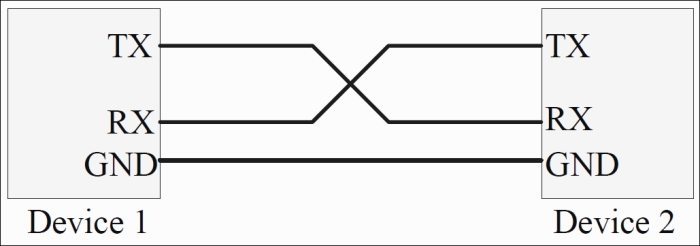
Null UART connection
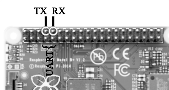
The following figure represents the UART pins on the GPIO header of the RasPi board. Pin 8 and 10 on the RasPi GPIO pin header are transmit and receive pins respectively.
Many sensors do have the UART communication protocol enabled on their output pins. Sensors such as gas sensors (MQ-2) use UART communication to communicate with the RasPi. Another sensor that works on UART is the nine-axis motion sensor from LP Research (LPMS-UARTL), which allows you to make quadcopters on your own by providing a three-axis gyroscope, three-axis magnetometer, and three-axis accelerometer. The TMP104 sensor from Texas instruments comes with UART interface digital temperature sensors. Here, the UART allows daisy-chain topology (in which you connect one's transmit to the receive of the second, the second's transmit to the third's receive, and so on up to eight sensors). In a RasPi, there should be a written application program with the UART driver in the Python or C language to obtain the data coming from a sensor.
The Serial Peripheral Interface (SPI) is a full-duplex, short-distance, and single-master protocol. Unlike UART, it is a synchronous communication protocol. One of the simple connections can be the single master-slave connection, which is shown in the next figure. There are usually four wires in total, which are clock, Master In Slave Out (MISO), Master Out Slave In (MOSI), and chip select (CS). Have a look at the following image:

Simple master-slave SPI connections
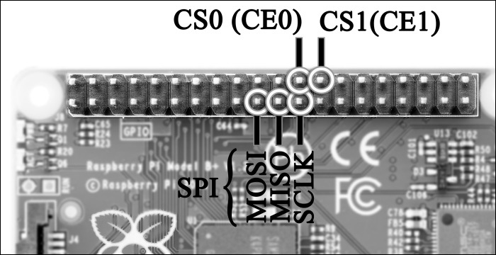
The master always initiates the data frame and clock. The clock frequencies can be varied from the master according to the slave's performance and capabilities. The clock frequency varies from 1 MHz to 40 MHz, and higher too. Some slave devices trigger on active low input, which means that whenever the logic zero signal is given by the master to slave on the CS pin, the slave chip is turned ON. Then it accepts the clock and data from master. There can be multiple slaves connected to a master device. To connect multiple slaves, we need additional CS lines from the master to be connected with the slaves. This can be one of the disadvantages of the SPI communication protocol, when slaves are increased. There is no slave acknowledgement sent to the master, so the master sends data without knowing whether the slave has received it or not. If both the master and the slave are programmable, then during runtime (while executing the program), the master and slave actions can be interchanged. For the RasPi, we can easily write the SPI communication code in either Python or C. Chapter 5, Using an ADC to Interface any Analog Sensor with the Raspberry Pi, comes with the use of the SPI protocol, in which we are going to interface a sensor station made by ourselves to log data. This logged data will be uploaded to the Internet and also sent to your own e-mail IDs. Interesting isn't it? The location of the SPI pins on RasPi 1 models A+ and B+ and RasPi 2 model B can be seen in the following diagram. This diagram is still valid for RasPi 1 model B:
Inter-Integrated Circuit (I2C) is a protocol that works with two wires and it is a half-duplex (a type of communication where whenever the sender sends the command, the receiver just listens and cannot transmit anything; and vice versa), multimaster protocol that requires only two wires, known as data (SDA) and clock (SCL). The I2C protocol is patented by Philips, and whenever an IC manufacturer wants to include I2C in their chip, they need a license. Many of the ICs and peripherals around us are integrated with the I2C communication protocol. The lines of I2C (SDA and SCL) are always pulled up via resistors to the input voltage. The I2C bus works in three speeds: high speed (3.4 MBps), fast (400 KBps), and slow (less than 100 KBps). It is heard that the I2C communication is done up to 45 feet, but it's better to keep it under 10 feet.
Each I2C device has an address of 7 to 10 bits; using this address, the master can always connect and send data meant for that particular slave. The slave device manufacturer provides you with the address to use when you are interfacing the device with the master. Data is received at every slave, but only that slave can take the data for which it is made. Using the address, the master reads the data available in the predefined data registers in the sensors, and processes it on its own. The general setup of an I2C bus configuration can be done as shown in the following diagram:
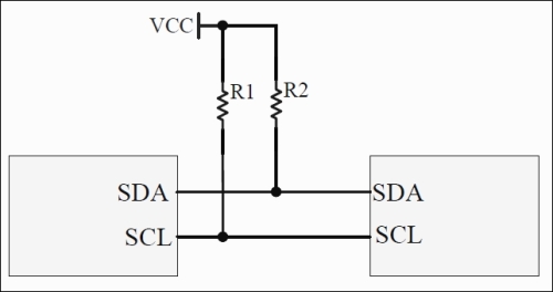
I2C bus interface
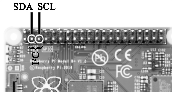
There are 16 x 2 character LCD modules available with the I2C interface in stores; you can just use them and program the RasPi accordingly. Usually, the LCD requires 8/4 wire parallel data bits, reset, read/write, and enable pins. The I2C pins are represented in the following image, and they can be located in the same place on all the RasPi models:
The I2C protocol is the most widely used protocol among all when we talk about sensor interfacing. Silicon Labs' Si1141 is a proximity and brightness sensor that is nowadays used in mobile phones to provide the auto-brightness and near proximity features. You can purchase it and easily interface it with the RasPi. SHT20 from Sensirion also comes with the I2C protocol, and it can be used to measure temperature and humidity data. Stepper motor control can be done using I2C-based controllers, which can be interfaced with the RasPi. The most amazing thing is that if you have all of these sensors, then you can tie them to a single I2C, but with RasPi you can get the data! You will get to know in the next section that we cannot use that many GPIOs on RasPi 1 model B or B+ and RasPi 2 model B. Therefore, the modules with the I2C interface are available for low-pin-count devices. This is why serial communication is useful.
These protocols are mostly used with the RasPi. The information given here about them is not that detailed, as numerous pages can be written on these protocols, but while programming the RasPi, this much information can help you build the projects.