
It's now time to connect the ultrasonic sensor with the RasPi board. The ultrasonic sensor works on a 5V power supply. Fortunately, we have the 5V supply pin on the RasPi board. We can provide the 5V supply from RasPi to the ultrasonic sensor. However, in reply, the ultrasonic sensor generates a 5V echo signal as an output to RasPi.
As you have read in Chapter 2, Meeting the World of Electronics, we know that our RasPi needs the 3.3V level on the GPIO pins to operate safely. So, how do we connect them? It is a serious matter. In this regard, Kirchhoff will help us. With the help of Kirchhoff's current and voltage laws, we can divide the voltage into two parts. If we divide the 5V supply into 3.3V and 1.7V, we can use the echo pulse coming out of the ultrasonic sensor to connect it to RasPi board's GPIO. To divide the voltage, we will simply follow the most common voltage divider circuits used in electronics.
Voltage divider is nothing but a combination of resistors with the right values connected in such a style that it divides the voltage. The standard value resistors should be used while creating the voltage dividers so that we can easily get them from the market.
There is a simple theory that we will follow. As shown in the following figure, a voltage divider consists of two resistors (sometimes, only one variable resistor). Usually, the resistor near the input voltage supply (Vin) is called R1 and the one near to the ground is called R2.
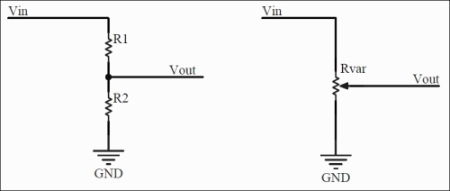
Voltage divider connections
With this configuration, the voltage drop across the resistor R2 should be calculated using this formula:

Similarly, if you use the variable resistor, also called as a potentiometer (POT), there is a slider in the center. This slider needs to be changed, and we have to look for the desired voltage on a digital voltmeter (multimeter).
I have a 1KΩ resistor with me, and it is one of the standard resistor values available. We already know that we need to convert 5V to 3.3V. So here, Vin will be 5V, and Vout will be 3.3V. Let's calculate the R2 value required to create this voltage divider.
Let's put values into the equation:

Then, let's solve the equation:
We get R2 = 1941.1Ω, and this value of resistor is not available in the market. However, fortunately, we have a resistor of 2KΩ that has a value very near to 1941Ω. The resistors we get from the market have tolerances of 5 percent to 10 percent. This means that resistance with these tolerance values are never exactly same as the tagged value. It always has some variance. As per the calculations, we need two resistors to build the voltage divider from 5V to 3.3V, which are 1KΩ and 2KΩ.
Connect the devices as per the guidelines given here and enjoy the coding in the next section. You will need these things on a neat wooden table or a table with an insulation sheet:
- An HC-SR04 ultrasonic range finder
- 1KΩ and 2KΩ resistors (if these seller asks about the wattage of a resistor, ask for 1/4 watts, also termed as quarter watts)
Note
If you do not have 1KΩ or 2KΩ resistor, you can use 330Ω and 470Ω resistors, respectively. You can cross-check the calculations done previously. The wattage of resistor states the maximum amount of power dissipated through a resistor. Higher the wattage, higher is the current that can pass through at a certain amount of voltage. P = V * I. So, 0.25W = 5V * I yields, I = 500 mA. Therefore, 1/4 watts can be sufficient on boards such as RasPi.
- One multimeter (if you are a geek and want to measure everything!)
- Female-to-male jumper wires and female-to-female jumper wires
- Breadboard (not compulsory if you can build this by just twisting the wires, but I recommend that you use it for proper connections without shorting each other)
- The RasPi with power adaptor
- An Ethernet cable
- A personal computer
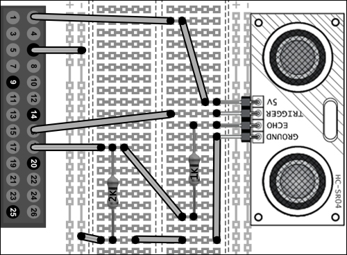
Now, we are ready to build the circuit. The circuit will look like the following diagram if you build it correctly. This diagram is also called as schematics, which represents every terminal of the components and their symbols.
For RasPi, we used the connector in the center with all its 26 pins (for RasPi 1 model B). We already know that RasPi 1 Model B, Model B+, and RasPi 2 Model B have the same functionality on the first 26 pins on header. Let's connect it step by step. It's more enjoyable if you understand the connections and connect it by yourself on the breadboard.

However, I have shown the connections on the breadboard in the following figure, which makes the connections easy to understand. The connections are also described here in a step by step. Black dots on the breadboard in the figure show the physical connections of the wire onto the breadboard. We will perform the following steps:
- Take the breadboard.
- Connect the sensor on the breadboard. Keep in mind that if you connect it flipped, the connections suggested here would not work. Cross-check the connections, and make sure that you make a correct circuit.
- Connect pin 6 of RasPi to the ground rail of the breadboard.
- Connect RasPi's pin 2 to the sensor's 5V pin.
- The trigger pin can be connected directly with the sensor. In fact, the RasPi sends 3.3V signal to this trigger pin, which is acceptable by the sensor.
- Take out a connection from RasPi pin 18 to the breadboard, and connect it to the terminal rails of breadboard. From the same row, you can connect one terminal of 2KΩ resistor. The second terminal goes to the same ground strip where RasPi's ground and sensor's ground are connected, as shown in the following image:
So far, the connections we have done are good to go. Cross-check the connection twice before you power up the RasPi. We have done the procedure on the hardware. We need to write the software (code) to tell the RasPi that we have connected this sensor to these pins and to calculate the distance based on the formulas we derived.
Let's start writing the code in Python. This code can be separated into the modules. These modules can then be integrated as a single code to get the distance. Let's summarize the steps here:
- Initial configuration
- Setting the GPIO pins on the default mode
- Sending the trigger signal and listening to the echo
- Calculation of time and distance
Let's see each of them in detail.
In the initial setup, we need to include or call the GPIO and time libraries, which we installed while reading Chapter 1, Meeting Your Buddy – the Raspberry Pi, into the Python environment, as shown in the following code:
import RPi.GPIO as GPIO
import time
GPIO.setmode(GPIO.BCM)
print "Measuring Distance"
As described earlier, the time library brings the timing and delay functionalities to the Python code. We will use the BCM mode to call the GPIOs of RasPi, as we did in Chapter 2, Meeting the World of Electronics.
We have connected the sensor's trigger and echo pins to pins 16 and 18 of RasPi, which are GPIO 23 and GPIO 24 in the BCM mode, respectively. We know that the trigger pin is the output pin for RasPi and input pin for sensor. The echo pin is the input pin for the RasPi. Here, it gets the response from the sensor after sending the trigger pulse. The following code depicts this:
GPIO.setup(23,GPIO.OUT)
GPIO.setup(24,GPIO.IN)
GPIO.output(23, False)
print "Setting Trigger pin to zero by default"
time.sleep(1)
If we analyze the timing diagram of the ultrasonic sensor to measure the distance, we can easily understand how the sequence should be. The following timing diagram shows the sequence. In the previous step, we made the trigger pin zero by default. Then, we provided a 10µs pulse to the trigger pin of the sensor from the RasPi. Once the sensor receives the trigger signal, it sends the 40 KHz pulse / ultrasonic burst from the built-in transmitter (contains eight pulses).
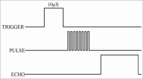
We should expect the echo signal after the ultrasonic burst signal. The length of the echo signal provides us with the timings for the distance calculations. How do we write in a code? The simple way to create a trigger pulse is by turning the pin high for 10µs, as shown in the following code:
GPIO.output(23, True)
time.sleep(0.00001)
GPIO.output(23, False)
Using this piece of code, we sent a pulse, and the ultrasonic sound burst is generated internally and transmitted into the air. It will reflect and come back to generate the echo pulse. We have to check it continuously until we get the echo pulse. As we saw in the previous figure, the echo pin remains high for a certain period of time. So, we need to calculate the amount of time while the echo signal received stays on. We can use the while() loop to continuously monitor the echo pin. We can use the time function to capture the time duration of echo while it remains high:
while GPIO.input(24) == 0:
     start_time = time.time()
This piece of code creates a kind of forever running loop until the echo pin changes its state from 0 (low) to 1 (high). While the echo pin is 0 (or low), we keep updating the timing value (timestamp) in the start_time variable. Once the echo pin goes high, the while() loop breaks, and we get the value of time when the echo pulse went from low to high low state. Next, we need to use the same logic to get the timestamp for the time it remains high. At this instance, we used another variable to store the timestamp so that later on, we can use both the variables to determine the time duration:
while GPIO.input(24) == 1:
     end_time = time.time()
The while() loop here keeps updating the variable with the latest time while the condition is true.
We have the start time and the end time of the echo pulse. So, we have to subtract both the values to get the pulse duration. Once we get the pulse duration, we can then use it for the distance calculation:
time = end_time - start_time
Initially, in the chapter, we derived a formula for distance calculation, which will be useful here. Let's recall it:
We considered the two-way journey of sound and then divided the time by the factor of 2.
Converting this formula into the Python script, we get the following code:
distance = 17150 * time
print "Measured Distance is :", distance, "cms"
We have understood the operation in parts. Let's join them together to get a completely working sensor with the RasPi. Write sudo nano distance.py in the PuTTY command line and start typing the following code:
import RPi.GPIO as GPIO
import time
GPIO.setmode(GPIO.BCM)
GPIO.setwarnings(False)
print "Measuring Distance"
print "Press ctrl+c to stop me"
GPIO.setup(23,GPIO.OUT)
GPIO.setup(24,GPIO.IN)
time.sleep(0.02)
GPIO.output(23, False)
print "Setting Trigger pin to zero by default"
time.sleep(1)
while True:
     GPIO.output(23, True)
     time.sleep(0.00001)
     GPIO.output(23, False)
     while GPIO.input(24) == 0:
          start_time = time.time()
     while GPIO.input(24) == 1:
          end_time = time.time()
     time = end_time – start_time
     distance = 17150 * time
print "Measured Distance is:", distance, "cms."Press Ctrl + X followed by Y and then press Enter to exit and save the code.
Compared to the steps to set up software, there are some minor changes in the compiled code. You will find that we used GPIO.setwarnings(False). This command turns off the warnings generated while compiling the code. When the program is started and the GPIOs are configured, give the RasPi module some time to get ready to take the readings. There is a need to use the while() loop. Using this forever-running loop, we can see the live distance variation by pointing the sensor towards different targets. Before we start to compile the project, check the connections again. Just ensure that the ultrasonic sensor is positioned well and pointed towards the target. Alternatively, just put the sensor perpendicular to the table so that the cylinders remain parallel to the table surface.
And here we go! Type sudo python distance.py and press Enter. Wonderful, isn't it? As we programmed and executed it, it now shows the output as Measured Distance is: 9.1321cms. We have created the ultrasonic distance meter. You can point it at various objects to measure the distance. I have tried to measure the distance from my table to the kitchen to know how much distance I walk every time I go to drink some water. You can stop the code by pressing Ctrl + C. This kills any script currently running in the Linux shell. You can use this command if the program is stuck in an infinite loop. This may mean that there is a software or a hardware bug.