We can build a project that understands that the temperature and light are high, and hence, would turn off the home tube lights while automatically turning the fan on! We can integrate the whole project and make an LED glow to show the decision made by the RasPi. Does this sound good?
Tip
Whenever we want to control home appliances, we need to be extremely cautious that they work on 110/230V AC and up to 15A of current. It is not recommended to connect the RasPi to any of the AC mains-operated home appliances directly. Relays (which provide good isolation) should be used to control the appliances. However, it is highly recommended that you perform any task related to relays and controlling appliances under the observation of an experienced electrician.
We can order the relay boards from any e-store. The relay boards are separately powered through an adapter or direct mains supply. The +5V or +3.3V pins of the RasPi should not be shared with these boards. Nevertheless, we can connect the GPIO and ground pins directly to the relay board input/trigger pins. For demonstration/testing purpose, we should connect LEDs on the GPIO port, and once the LEDs are tested successfully, we can interface the relay board. The working will remain the same. For testing, this project we will not require any electrician, as we will make the LEDs glow.
First of all, we will merge the codes of the DHT11 and LDR sensors. To match the timings, some parts of the code will be a new addition to the previous two codes we wrote for DHT and LDR. We will define some include libraries, such as standard input/output (stdio), standard integer library (stdlib) (because we will break the 8-bit integer into binary bits), and wiringPi to get support of the RasPi GPIO. We have defined some of the integers as uint8_t to define them as 8-bit data.
Tip
In code, the LDR, DHT, and LED devices are defined as 7, 4, and 0, respectively. As we are using the wiringPi library, they are GPIO numbers that would be same for model B and B+ (previously, it was BCM and Board modes). To know the exact wiringPi pin numbers mapped to the RasPi GPIO pin header, type gpio readall command in the terminal. This command will give you a table of all the naming conventions followed in the RasPi as output. This is very useful when we code with different libraries.
Open PuTTY on your PC by connecting it to the RasPi through an Ethernet cable and type the sudo nano dhtldr9.c command to enter the code to get this project up and running:
#include <wiringPi.h>
#include <stdio.h>
#include <stdlib.h>//Library for integer arithmetic and conversion
#include <stdint.h>//Standard Integer Library
#define DHT 4 //RasPi GPIOHeader Pin 16
#define LDR 7 //RasPi GPIOHeader Pin 7
#define LED 0 //RasPi GPIOHeader Pin 11
int data[5], count, index, k, val[1000],sum=0;
int main(void)
{
if ( wiringPiSetup() == -1 ) //Check and call wiringPi library
{exit( 1 );}
pinMode(LED,OUTPUT); //Set LED pin to Output
digitalWrite(LED,LOW); //Make LED OFF by default
while ( 1 )
{
uint8_t prev_state= HIGH;
uint8_t value= 0;
uint8_t j= 0, pulse;
for(k=0;k<5;k++)
{ data[k] = 0;} //Clear the data in array
pinMode( DHT, OUTPUT );
digitalWrite( DHT, LOW );
delay( 18 );
digitalWrite( DHT, HIGH );
delayMicroseconds( 40 );
pinMode( DHT, INPUT ); //Initial Handshake between Sensor
and RasPi
for ( pulse = 0; pulse < 100; pulse++ )
{
value = 0;
while ( digitalRead( DHT ) == prev_state )
{
value++;
delayMicroseconds( 1 );
if ( value == 255 )
{break;}
} //while loop ends here
prev_state = digitalRead( DHT );
//Catching the data into the data Array
if ( value == 255 )
break;
if ( (pulse >= 4) && (pulse % 2 == 0) )
{
data[j / 8] <<= 1;
if ( value > 16 )
data[j / 8] |= 1;
j++;
}
} //for loop ends here
if ( (j >= 40) &&
(data[4] == ( (data[0] + data[1] + data[2] + data[3]) &
0b11111111) ) ) //Verifying the Checksum, Validate and Print the data
{
printf( "Humidity = %d.%d %% Temperature = %d.%d 'C
",
data[0], data[1], data[2], data[3]);
}
else
{
printf( "Data received is corrupted, what did you do?
" );
}
pinMode(DHT, OUTPUT);
digitalWrite(DHT, HIGH);
//LDR code initialization
for (index=0;index<50;index++) //Setting Code to get 50 values and store into array
{
pinMode (LDR, OUTPUT);
digitalWrite (LDR, LOW);
delay(16);
count=0;
pinMode (LDR, INPUT);
while (digitalRead(LDR)==LOW)
count++;
val[index]=count;
}
sum=0;
for (index=0;index<50;index++)
sum+=val[index]; //Take sum of all values in Array
printf("LDR Value is %d
",sum/250); //Take average of sum and
scale by 5 and print the data
if(data[2]>25 && sum>4000) //Check the Temperature and Light
Condition
{
digitalWrite(LED,HIGH);
printf("TEMPERATURE IS HIGH >> FAN ON, LIGHT IS LOW >> TUBELIGHT ON
");
}
delay(500); //Adjusting the Delay to match DHT11's minimum
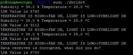
request timeNow, after typing the code into your RasPi, just press Ctrl + X followed by Y. Then, press Enter to save the changes. Enter the gcc dhtldr9.c -o dhtldr9 -lwiringPi command to compile the code. Then, enter the sudo ./dhtldr9 command to execute the code.
The following screenshot shows the output of the sudo ./dhtldr9 command: