
It is essential to gain knowledge of the ADC modules that we have gone through, and it is good to go with the hardware setup. We know that MCP3008 has eight channels to interface eight different single-ended output analog sensors. What if we build a project that has as many sensors as eight? Do you want to create generic hardware that has the capability of connecting any sensor with your RasPi? This section will contain the development of generic hardware that can seamlessly work with RasPi to interface whichever sensors you want. We can call that hardware by giving a name as a sensor station.
Tip
Not all sensors can be directly interfaced through MCP3008 with the RasPi. As described in the introduction to the ADC convertor, some sensors' output is so noisy or weak that it needs external filters and amplification for those respective sensors. It is recommended to read the datasheets of that particular sensor to know the required additional circuitry to be interfaced.
Until Chapter 4, Monitoring the Atmosphere Using Sensors, we used breadboards to create rapid prototyping hardware. We can prepare a circuit on a clean and reusable general-purpose circuit board (GPCB) by soldering the components. A GPCB can be useful for fulfilling our requirement for making the generic hardware. Still, if you don't want to buy the GPCB, this section will give you the idea of making the circuit on a breadboard. This is because preparing a circuit on a GPCB requires some soldering instruments, materials, and skills of soldering; it would rather be easy to use a breadboard. But there is much more fun in building a hand-soldered project. If you don't have soldering skills, you can build up your skills in an hour or two by practicing on junk hardware. Give it a try!
Here's the list of the hardware we need to purchase in order to start the hardware development:
- A general-purpose circuit board, dual-sided and solderable (2.54 mm pitch)
- Soldering iron (pencil type, 30 W to 50 W) and soldering core with flux
- MCP3008 (eight-channel) or MCP3004 (four-channel and DIP package)
- A single-stranded wire (20-30 AWG)
- A wire stripper
- One dual bergstik connector (male, 2 x 13 pins, 2.54 mm pitch); one single bergstik connector (male, 1 x 8 pins, 2.54 mm pitch); and three single bergstik connectors (male, 1 x 5 pins, 2.54 mm pitch)
- A GPIO ribbon cable for the RasPi 1 model B (26-pin) or B+ (40-pin) and the RasPi 2 model B (40-pin and female to female)
- LM35 or LM36; also known as TMP36 or temperature sensor (TO-92 package)
- Male-to-female and female-to-female jumper wires
- The Raspberry Pi, a power adapter, an Ethernet cable, and a personal computer
Place these components on your workbench and start building the circuitry, as shown in the following schematic diagram:
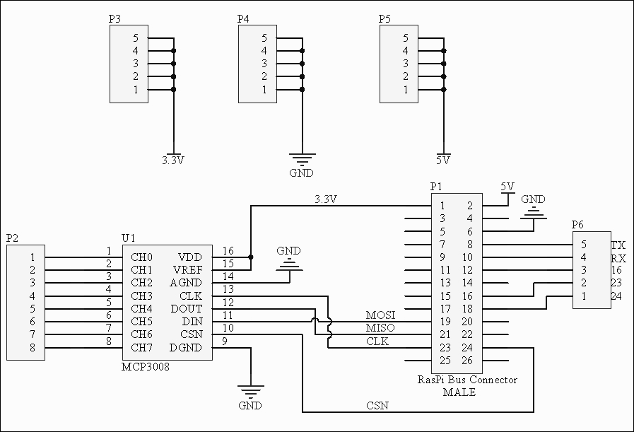
This hardware can now be used to create a generic interface to retrieve data from up to eight different sensors. This hardware setup will be done apart from the RasPi board connections. Once this circuit has been built, we will interface it using the ribbon wire. Let's cover the connectors in the schematic diagram. The second connector from the rightmost area of circuit, labelled as P1, is the 2 x 13 bergstik pin male header of the RasPi 1 model B.
If you have the RasPi 2 model B or the RasPi 1 model B+, then you'll have to use the 2 x 20 bergstik pin male header in place of the P1 connector. The rest of the circuit remains the same.
With the P1 connector, we join the P6 connector in the right to get the functionality of GPIO and UART communication. If needed, we can use it to toggle LEDs or to communicate with some other board or hardware. Pins 19, 21, 23, and 24 are the standard four-wire SPI interface connections net, labelled as MOSI, MISO, CLK, and CSN respectively. On MCP3008, we have provided +3.3V to VREF and VDD of the chip. In our new calculations, we will use 3.3 as Vref while developing the software. The analog and digital ground should be tied together while soldering the circuitry on the GPCB. The P2 connector in the leftmost area of the schematics will be used to connect the analog output pins of different sensors. Connectors P3, P4, and P5 can be used to connect +3.3V, Ground, and +5V to the sensor as per the requirement.
Hold the general-purpose board in your hand and you will notice that it has copper-plated holes. These copper-plated holes can be used to solder the components. Take a look at the top view of the representational circuitry built on the GPCB, as shown in the following diagram:

The circuit looks straightforward and same as the schematics. By keeping some space on the left side, insert the connectors into the suggested positions. Here, the 2 x 13 bergstik pin male header can be used to connect the RasPi GPIO using the standard GPIO ribbon cable. If you have model B+ or the RasPi 2 model B, then you can also use the same hardware with the 2 x 20 pin bergstik header. Instead of wiring, you can pour the solder to connect the chip and the connectors. The black lines shown in the preceding diagram are the soldered pads on the GPCB. Just use the iron and solder along the entire path as shown in the figure. One thing that needs to be taken care of is that the MISO, MOSI and CLOCK signals have to be connected using the wires, as they are crossing each other. Therefore, they are represented in grey. Without wiring, it is not possible to solder the whole line from the RasPi connector to MCP3008 without shorting each other.
Tip
Soldering irons are too hot when they are at their peak temperature. Be extremely cautious while using them. There could be the chance that you put the iron on wires, your own table, or your own hands! Use a soldering iron stand to place the hot soldering iron when not in use.
While soldering the MCP3008 chip, do not keep the soldering iron near the leads of the IC for a long time. The soldering irons are typically hot, from 250 degree Celsius to 400 degree Celsius. Long exposure to higher temperatures can damage the IC.
After preparing the hardware, we are ready to prepare the code by powering up the RasPi and connecting it with the PC over SSHing through PuTTY using an Ethernet cable. At this moment, there is no need to connect the hardware module that we created just now. Once we write the software as described in the next section, we then will connect hardware module to the RasPi using the ribbon/bus connector.