
Chapter 10: Data Pipeline Management
Our data is composed of a lot of data types, such as IoT device logs, user logs, web server logs, and business reports. This data is generally stored in multiple data sources, such as relational databases, NoSQL databases, data warehouses, and data lakes, based on your applications, business needs, and rules. In this situation, there might be cases where you must obtain aggregated data results for user analysis, cost reports, and building machine learning models. To obtain the results, you may need to implement data processing flows to read data from multiple data sources by using a programming language, SQL, and so on. We usually call these flows data pipelines.
Recent pipeline flows consist of extracting data from data sources, transforming the data on computing engines, and loading the data into other data sources. This kind of pipeline is called an extract, transform, and load (ETL) pipeline, and it is used in a lot of cases. Additionally, the extract, load, and transform (ELT) and extract, transformation, load, and transformation (EtLT) patterns are used these days.
As you grow your data and data sources, the number of data pipelines increases. This can usually cause problems in scaling data pipelines, such as how you can build, operate, manage, and maintain pipelines. Therefore, effectively building and using data pipelines is one of the keys to effectively utilizing and operating your data for the growth of your company, organization, and team.
To tackle these problems, in this chapter, we’ll look at data pipelines and the best practices to manage them. In particular, this chapter covers the following topics:
- What are data pipelines?
- Selecting the appropriate data processing services for your analysis
- Orchestrating your pipelines with workflow tools
- Automating how you provision your pipelines with provisioning tools
- Developing and maintaining your data pipelines
Technical requirements
For this chapter, if you wish to follow some of the walkthroughs, you will require the following:
- Internet access to GitHub, S3, and the AWS console (specifically the console for AWS Glue, Amazon Step Functions, Amazon Managed Workflows for Apache Airflow, AWS CloudFormation, and Amazon S3)
- A computer with Chrome, Firefox, Safari, or Microsoft Edge installed and the AWS Command Line Interface (AWS CLI)
Note
You can use not only the AWS CLI but also AWS CLI version 2. In this chapter, we have used the AWS CLI (not version 2). You can set up the AWS CLI (and version 2) by going to https://docs.aws.amazon.com/cli/latest/userguide/cli-chap-getting-started.html.
You will also need an AWS account and an accompanying IAM user (or IAM role) with sufficient privileges to complete this chapter’s activities. We recommend using a minimally scoped IAM policy to avoid unnecessary usage and making operational mistakes. You can find the IAM policy for this chapter in this book’s GitHub repository at https://github.com/PacktPublishing/Serverless-ETL-and-Analytics-with-AWS-Glue/tree/main/Chapter10. This IAM policy includes the following access:
- Permissions to create a list of IAM roles and policies for creating a service role for an AWS Glue ETL job.
- Permissions to read, list, and write access to an Amazon S3 bucket.
- Permissions to read and write access to Glue Data Catalog databases, tables, and partitions.
- Permissions to read, list and write access to Glue ETL Jobs, Crawlers, Triggers, Workflows and Blueprints.
- Permission to read, list and write access to AWS Step Functions resources.
- Permission to read, list and write access to Amazon Managed Workflows for Apache Airflow (MWAA) resources.
- Permissions to read, list and write access to AWS CloudFormation resources.
If you haven’t set up the following resources, create or install necessary resources by following AWS documents:
- An S3 bucket for reading and writing data by AWS Glue. If you haven’t had it yet, you can create one by going to the AWS console (https://s3.console.aws.amazon.com/s3/home) and choosing Create bucket. You can also create a bucket by running the aws s3api create-bucket --bucket <your_bucket_name> --region us-east-1 AWS CLI command.
- The environment for Glue Blueprints. If you haven’t set it up yet, you need to install the relevant modules and SDKs to use Glue Blueprints. Please refer to https://docs.aws.amazon.com/glue/latest/dg/developing-blueprints-prereq.html.
- The Amazon Managed Workflows for Apache Airflow (MWAA) environment. If you haven’t set it up yet, you need to create the environment from the MWAA console (https://console.aws.amazon.com/mwaa/home#environments). Please refer to https://docs.aws.amazon.com/mwaa/latest/userguide/get-started.html. At the time of writing, the latest Airflow version in MWAA is 2.2.2. This is the version we used.
What are data pipelines?
We generally use the word pipeline for a set of elements that are connected in a process, such as oil pipelines, gas pipelines, marketing pipelines, and so on. In particular, an element that is put into a pipeline is moved out via defined routes in a pipeline as output.
In computing, a data pipeline (or simply a pipeline) is referred to as a set of data processing elements that are connected in some series. Through a data pipeline, a set of elements are moved and transformed from various sources into destinations based on your implementation. A data pipeline usually consists of multiple tasks, such as data extraction, processing, validation, ingestion, pre-processing for machine learning use, and so on. Regarding the input and output of data pipelines, for example, the input is application logs, server logs, IoT device data, user data, and so on. The output of a data pipeline is analysis reports, a dataset for machine learning. The following diagram shows an example of a pipeline:
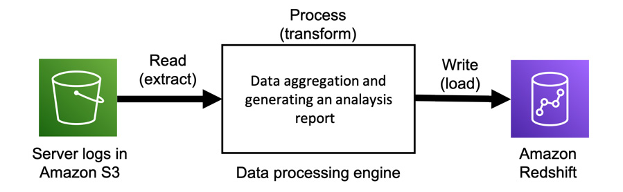
Figure 10.1 – A data pipeline that writes processed logs to an Amazon Redshift table
In this example, server logs are stored in S3 as raw data and are processed into an analysis report, then written to Amazon Redshift.
Usually, we run multiple pipelines as workflows by using scripts or automation tools. This creates various processed data to meet the various needs of multiple teams across multiple environments, such as multiple systems, programming languages, and so on.
Why do we need data pipelines?
We build and use data pipelines to process data and get results so that we can use the data further. Let’s take a look at some popular use cases of data pipelines:
- Data aggregation: Through data pipelines, your data is processed and aggregated to generate a result that meets customer, team, and organization needs, such as analysis reports, cost usage reports, user activity reports, and so on. After processing the data via data pipelines, it’s stored in various places, such as databases, data warehouses, and so on. If necessary, the aggregated data can be processed and combined with other aggregated data to generate a new report.
- Data cleansing: This use case is usually used for the raw data in your storage, such as application logs, user activity logs, server logs, IoT device data, and so on. Raw data often includes corrupted or garbage records. If you transform the raw data into data that other members such as analysts can process and visualize, you need to clean the raw data and also transform the data so that it matches your data source interface. For example, if analysts run analytic queries for a company’s data warehouse, you need to transform the data into a new format so that it is compatible with the data warehouse schema.
- Data anonymization: Sensitive records in your data are masked and transformed as a password through data pipelines. This process aims to provide privacy protection. This type of data pipeline often consists of multiple tasks that process sensitive information based on various levels of privacy. For example, let’s say that some data may include a user ID that must be masked for one team. However, another team needs that record, so the data doesn’t need to be processed.
Now that we’ve looked at some data pipeline use cases, others are available. Data pipelines are widely used to process and transform data into a new form of data for future use.
How do we build and manage data pipelines?
So far, we’ve seen that a data pipeline is a set of data processing flows that consist of elements of data processing and data storage. We’ve also seen that data pipelines are used for data aggregation, cleansing, anonymization, and more.
To achieve this kind of data processing with pipelines, you need to design and build pipelines. Additionally, you need to update and maintain your pipelines based on your needs and data, such as organization/team updates, data schema changes, system updates, and so on. To effectively build and manage your data pipelines, you must understand the four main components of data pipeline management. We will cover these in the following sub-sections.
Selecting data processing services for your analysis
When you build a pipeline that extracts/writes data from/to your data storage, such as Amazon S3, relational databases, data warehouses, and so on, as a first step, you need to determine which data processing engines or services you use and how you process the data with them. To select data processing services, you need to consider things such as data usage, data format, data processing time, data size (which you try to process), and the relevant requirements such as the service latency, usability, flexibility, and so on. We’ll cover the details of selecting data processing services in the Selecting the appropriate data processing services for your analysis section.
Orchestrating data pipelines with workflow tools
After building data pipelines combined with data processing services and your data sources, you may need to automate running your pipelines as a workflow to easily and safely run them without manual work. For example, you can create a scheduled-based workflow that automatically runs multiple pipelines, including multiple data processing jobs and multiple data sources, every morning. To run these pipelines, you don’t need to manually run them one by one. You’ll learn how to orchestrate your pipelines and workflow tools in the Orchestrating your pipelines with workflow tools section.
Automating how you provision your data pipelines and workflows
You can automatically run multiple data pipelines as a workflow with workflow tools. So, how can you build and manage multiple workflows if you have a lot of workflows? For example, let’s assume you need to build hundreds of data pipelines that consist of the same data processing but various data sources. You can’t imagine creating those pipelines each by one.
For this kind of use case, you can provision pipelines and workflows by using a template you define resources in with various provisioning tools, which we’ll look at in the Automating how you provision your pipelines with provisioning tools section. Additionally, using provisioning tools, you can not only automate provisioning resources but also manage your resources via a template. By defining your pipeline resources with a template without manual operations in GUI applications, you can manage them with a versioning system and safely deploy them on your system by applying tests.
Developing and maintaining data pipelines
To build data pipelines and the relevant components, you also need to think about how you build them. In particular, you need to continuously update them without bugs based on company/organization/team requirements, business needs, and so on. To achieve effective development cycles, a good solution is to apply the software practices of continuous integration (CI) and continuous delivery (CD) to your data pipeline development process. These concepts help with problem detection, productivity, release cycles, and so on. You learn how to utilize these concepts in your data pipelines development and management in the Developing and maintaining your data pipelines section. You’ll learn how to develop Glue ETL jobs locally and how to deploy the ETL jobs and workflows in your environment in the section.
Next, we will cover four topics that we’ve looked at previously in terms of building and managing data pipelines using AWS Glue and combining it with other AWS services.
Selecting the appropriate data processing services for your analysis
One of the most important steps in using data processing pipelines is selecting the data processing services that meet the requirements for your data. In particular, you need to pay attention to the following:
- Whether your computing engine can process the data with the fastest speed you can allow
- Whether your computing engine can process all your data without any errors
- Whether you can easily implement data processing
- Whether the resource of your computing engine can easily be scaled as the amount of data increases (for example, you can scale it without making any changes to your code)
For example, if your data processing service doesn’t have more memory capacity than your data, what does the computing engine do to your job? Having less memory capacity can cause out-of-memory (OOM) issues in your processing jobs and cause job failures. Even if you can process the data with that small memory capacity, it will slow down your data processing compared to processing the data in memory since you need to put some data aside in your disk to avoid issues. As another example, assuming that your job processes your data with a single node, what happens to your processing job in the future if the amount of data increases? You may need to scale up or scale out your computing resource for the engine as the job will need more time to process data as the amount of data increases. Then, when your computing engine reaches its limits in terms of its processing capabilities, you may need to select another computing engine that can process your data.
AWS provides multiple data processing services, such as AWS Lambda, AWS Glue, Amazon Athena, Amazon EMR, and more to match your environment’s use cases and needs. In this section, we’ll walk through each AWS-provided service for building data pipelines. Then, you’ll learn how to choose the engine that satisfies your needs.
AWS Batch
AWS Batch is a fully managed service for running batch computing workloads based on your definition. Computing resources for AWS Batch are managed by AWS instead of customers. AWS Batch automatically provisions the resources and also optimizes your workload distribution based on workloads.
To run your batch computation, you must submit a unit of work, such as a shell script, a Linux executable, or a Docker container image, to AWS Batch. This definition is handled as a job. You can also flexibly define how jobs run – in particular, how many resources, such as CPU and memory, will be used, how many concurrency jobs will run, when AWS Batch executes jobs, and so on.
To use AWS Batch as a data processing service, you need to create a unit of work, a resource definition, and job scheduling. It runs on a single instance that you specify, so you need to care about resource limits such as memory, CPU, and so on. For more details about AWS Batch, please refer to https://docs.aws.amazon.com/batch/latest/userguide/what-is-batch.html.
Amazon ECS
Amazon Elastic Container Service (ECS) is a fully managed container orchestration service based on your container in a task definition. ECS also provides a serverless option, which is called AWS Fargate. Using Fargate, you don’t need to manage resources, handle capacity planning, or isolate container workloads for security purposes.
Using ECS, all you need to do is build Docker images. After building these Docker images, you can deploy and run your images on ECS. You can also use this service as not only an application service but also as a data processing engine for big data. For example, you can deploy Apache Spark clusters, Kinesis Data Streams consumers, and Apache Kafka consumers by building Docker images.
Regarding container resources, ECS provides a wide variety of container instance types that are provided by Amazon EC2. Therefore, allocated resources such as memory and vCPUs are based on your instance images. Please refer to https://docs.aws.amazon.com/AmazonECS/latest/developerguide/ECS_instances.html regarding container instances.
AWS Lambda
AWS Lambda is a serverless computing service that runs your implemented code as Lambda functions on AWS-managed high-availability resources. All you need to do is write your code with a supported programming language, such as Python, Java, Node.js, Ruby, Go, or .NET, and a custom runtime.
Based on requests to Lambda, Lambda runs your defined Lambda functions with scaling automatically to respond to the requests. It can respond to up to 1,000 per second. You can use Lambda for a lot of use cases. The following are some examples:
- It can process batch-based data stored in S3
- It can process streaming-based data from streaming data sources such as DynamoDB Streams, Kinesis Data Streams, Managed Streaming Kafka, and others.
- It can work as an orchestrator of data pipelines to run data processing services such as AWS Glue, Amazon Athena, Amazon EMR, and others.
In addition to implementing the Lambda function code, you can set Lambda’s resource configuration as follows:
- Memory (MB): This determines the amount of memory that’s available for your Lambda function. You can set this value between 128 MB and 10,240 MB. Regarding CPUs, they are linearly in proportion to the amount of memory that’s been configured (at 1,769 MB, a function has the equivalent of 1 vCPU).
- Timeout (seconds): This determines the Lambda execution timeout. If a function’s execution exceeds this timeout, its execution is stopped. You can set this value to a maximum of 15 minutes.
Additionally, you can set asynchronous invocation, function concurrency, and so on.
As we’ve discussed, Lambda can be used in a lot of use cases and situations based on its implementation style. Therefore, it might be good to start using Lambda as a data processing service if you don’t have a big data software environment such as Apache Hadoop, Apache Spark, and so on. Note that Lambda has memory limitations and that sometimes, duplicate invocation occurs.
Amazon Athena
Amazon Athena is a serverless query service. It allows you to run standard SQL queries for various data sources, such as CSV, JSON, Apache Parquet, Apache ORC, and so on, which are stored in your data stores, such as Amazon S3, JDBC/ODBC resources, and so on. Athena is based on Presto (https://prestodb.io), which provides a distributed SQL engine. This is useful for running ad hoc queries to obtain the analytical results of your data.
The Athena console provides an interactive view for users to easily run SQL queries, as shown in the following screenshot:
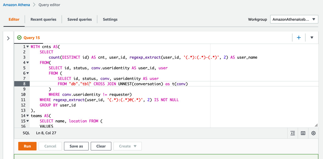
Figure 10.2 – Obtaining analytic data results by running a SQL query from the Athena console
In addition to the console, you can access Athena with APIs (https://docs.aws.amazon.com/athena/latest/APIReference/Welcome.html), SDKs (https://aws.amazon.com/getting-started/tools-sdks/), and more.
Athena can work with Glue Data Catalog as a Hive-compliant resource. Using Athena, you can create and read tables in/from the Data Catalog. If you need a data processing pipeline, you can build it with Athena. For example, you can build a simple pipeline so that Athena extracts data from S3 after creating a table with a Glue crawler, then writes the aggregated data to S3 using the access to Athena. This pipeline can be built by implementing a script that automates Athena queries and running the StartQueryExecution API (https://docs.aws.amazon.com/athena/latest/APIReference/API_StartQueryExecution.html) with AWS SDKs.
Athena charges your queries based on their data scanning size in terabytes. For more details about pricing, please refer to https://aws.amazon.com/athena/pricing/.
NOTE – Athena Service Quotas
When using Athena, you need to consider that Athena has default query quotas. For more information about service quotas, please refer to https://docs.aws.amazon.com/athena/latest/ug/service-limits.html.
AWS Glue ETL jobs
In AWS Glue ETL jobs, you can choose from Spark, Spark Streaming, and a Python shell. We’ll look at these types here.
Spark
In terms of Spark, you can run Apache Spark applications as Glue jobs (hereafter, Glue Spark jobs) and process your data within Glue and Spark frameworks. To run Glue Spark jobs, you don’t need to set up any resources for the computation. However, you need to implement scripts to process your data with Scala, Python (called PySpark), or SQL (called SparkSQL). Glue and Spark also provide many methods so that data processing can be enabled easily with a few pieces of code. The Data ingestion from streaming a data source section in Chapter 3, Data Ingestion, describes what Glue Spark is and how to use it. In Glue Spark jobs, you can choose a worker type that defines the memory, vCPUs, and disk size of each worker. Worker type is determined by your processing workloads, such as Standard for general use cases, G.1X for memory-intensive jobs, and G.2X for machine learning (ML) transform jobs.
Each worker type has a fixed allocated memory, vCPUs, and disk. At the time of writing, the details shown in the following table about these allocated resources are correct:
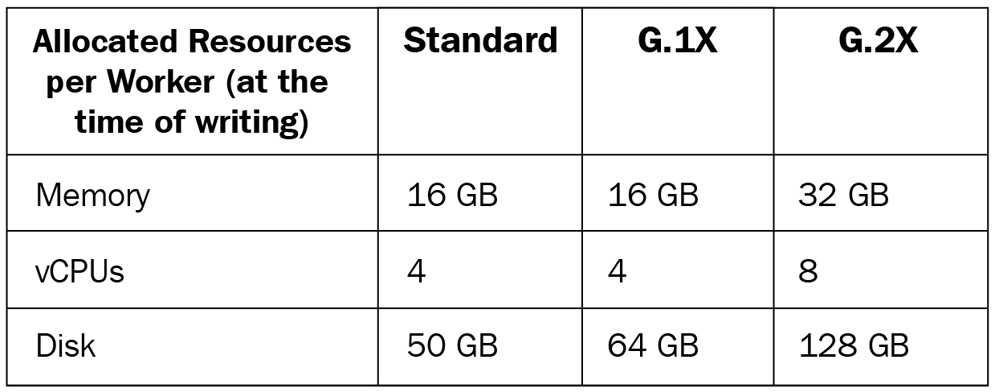
Figure 10.3 – Allocated resources of each worker type
In addition to the worker types, you need to set the number of workers, which defines how many workers with a specific worker type concurrently process your data.
The worker type and the number of workers define the capacity of the Glue computing resource (in other words, the Spark cluster) for your job. Specifically, they define how much memory and disk the job can use and how much concurrency the job processes. For example, when you set 10 G.1X workers to your Glue Spark job, the job can use a maximum of 160 GB memory, 40 vCPUs, and 640 GB disk for your entire Spark cluster.
Note – Data Processing Units (DPUs) and Maximum Capacity
The number of DPUs defines how many resources are allocated to your job. You are charged based on the DPUs you use in your job (please refer to https://aws.amazon.com/glue/pricing/ for more information). A DPU has 4 vCPUs with compute capacity and 16 GB of memory.
The maximum capacity is the same as the number of DPUs (for example, if you set 10 DPUs, the maximum capacity is also 10). When you choose Glue 1.0 and the Standard worker type, you need to set the Maximum capacity option instead of the Number of workers option.
Using Glue Spark jobs, you can use a distributed processing engine based on Spark, process your data with a lot of data processing methods, easily scale computing resources by changing the number of workers, and more.
Spark Streaming
Spark Streaming is one of the modules in Apache Spark for processing streaming data. This is different from Spark, which is typically used for batch jobs. Spark Streaming is used for streaming jobs for Glue (hereafter, Glue Streaming jobs). You can also implement Glue Streaming jobs with Scala, Python, or SQL, similar to Glue Spark jobs. The Data ingestion from streaming a data source section in Chapter 3, Data Ingestion, describes what Glue Streaming is and how to use it.
Regarding worker types and the number of workers for Glue Streaming jobs, you can configure them in the same way as you configure Glue Spark jobs. If you process the streaming data from streaming sources such as Amazon Kinesis Data Streams, Apache Kafka, and others, you can use this type. You are charged based on the DPUs per second you used in your job.
Python shell
If you select the Python shell type, you can run pure Python scripts, not PySpark, as Glue jobs (hereafter, Python shell jobs) on the Glue environment. Similar to the other Glue job types, you don’t need to set up any resources for the computation. The Data ingestion from the Amazon S3 object store section in Chapter 3, Data Ingestion, describes what a Python shell is and how to use one.
Regarding worker types and the number of workers, you can only set the maximum capacity or DPUs for a Python shell job, not the worker types and number of workers. In particular, you can set the value to 0.0625 (the default DPU value) or 1. In addition to this, Python shell jobs can be integrated with other Glue components such as crawlers and Glue Spark jobs using a Glue workflow (which we’ll see later in this chapter). You can also configure the job’s timeout. The default is 48 hours.
When you don’t need distributed processing via Spark jobs but you have a long-running job that, for example, simply checks multiple objects in S3 and deletes some objects based on a condition, you can use this type. You are charged based on the DPUs per second you selected (0.0625 or 1) in your job.
Amazon EMR
Amazon EMR (hereafter, EMR) provides a cluster management platform where you can run multiple big data-related applications such as Apache Hadoop, Apache Spark, Apache Hive, Presto/Trino, Apache HBase, Apache Flink, TensorFlow, and others in their latest versions. In addition to these applications, EMR also provides a lot of functionalities such as steps, bootstrap actions, and cluster configuration. We’ll provide a summary of EMR here.
When you run multiple software applications, you don’t always need to call each service API or log in each console/interactive shell. You can run these applications via EMR Steps (https://docs.aws.amazon.com/emr/latest/ManagementGuide/emr-work-with-steps.html), which runs applications on your behalf by adding your application implementation to EMR Steps.
You can also configure your cluster, such as its size, EC2 instance types, multiple versions of applications that match your needs, and so on. You can also add the software that you need to create an EMR cluster via the EMR Bootstrap action (https://docs.aws.amazon.com/emr/latest/ManagementGuide/emr-plan-bootstrap.html). This can be defined by implementing scripts and setting these scripts when creating the cluster. It’s also possible to connect to AWS Glue Data Catalog.
Compared to AWS Glue, EMR enables you to provide various flexible options for selecting applications, cluster size, cluster scaling, cluster nodes, customizing the cluster node system, and so on. Furthermore, you can choose a cluster running environment from Amazon EC2 (EMR on EC2), Amazon EKS (EMR on EKS), AWS Outposts, and Serverless (this is a preview feature). However, note that EMR is not serverless except for EMR Serverless, so you need to manage clusters yourself.
Regarding EMR pricing, you are charged based on your running node type and running duration. For more details, please refer to https://aws.amazon.com/emr/pricing/.
Orchestrating your pipelines with workflow tools
After selecting the data processing services for your data, you must build data processing pipelines using these services. For example, you can build a pipeline similar to the one shown in the following diagram. In this pipeline, four Glue Spark jobs extract the data from four databases. Then, each job writes data to S3. In terms of the data stored in S3, the next Glue Spark job processes the four tables’ data and generates an analytic report:
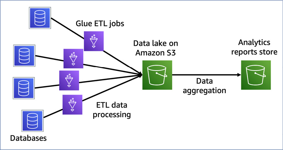
Figure 10.4 – A pipeline that extracts data from four databases, stores S3, and generates an analytic report by the aggregation job
So, after building a pipeline, how do you run each job? You can manually run multiple jobs to extract multiple databases. Once this has happened, you can run the job to generate a report. However, this can cause problems. One such problem is not getting a result if you run the generating report job before all the extracting jobs are completed. Another problem is that it will take a long time to generate a report if one of the extracting jobs takes a lot of time.
To avoid these problems, you can orchestrate pipelines with workflow tools such as AWS Glue workflows, AWS Step Functions, Apache Airflow, and others. Workflow tools for big data pipelines generally orchestrate not only multiple jobs but also multiple pipelines.
Recent modern workflow tools, such as the ones mentioned previously, represent the flow of jobs and the dependencies of jobs in a pipeline as a graph – in particular, a directed acyclic graph (DAG). A DAG has direction for each edge, but no directed cycles. In a cycle graph, the first and last edges are equal. The following diagram shows a DAG that represents the workflow example from earlier in this section, which involved generating a report pipeline:
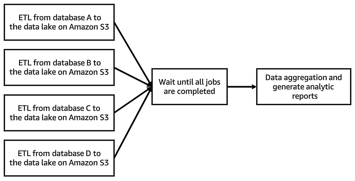
Figure 10.5 – A DAG workflow for generating a report pipeline
Using workflow tools, you can manage multiple jobs and pipelines as one workflow. Regarding the example of generating a report, a workflow tool can run each job, which may include extracting data from multiple databases, waiting for each job to complete, and generating a report. Thus, you don’t need to run each job manually.
In this section, we’ll walk through the workflow tools that AWS provides and learn how to combine them with the data processing services we looked at in the Selecting the appropriate data processing services for your analysis section:
- AWS Glue workflows
- AWS Step Functions
- Amazon Managed Workflows for Apache Airflow (MWAA)
First, we’ll look at AWS Glue workflows.
Using AWS Glue workflows
AWS Glue workflows allow you to create workflows that combine dependent Glue functionalities such as crawlers and ETL jobs as an orchestrator. In particular, Glue workflows execute crawlers and ETL jobs using Glue Trigger, which triggers crawlers and ETL jobs based on your configuration, such as on-demand, scheduled, or conditional, or via an EventBridge trigger. More information was provided in the Triggers section of Chapter 2, Introduction to Important AWS Glue Features. In addition to the role of the orchestrator, Glue workflows allow you to monitor each workflow component’s status, such as the success of ETL jobs, the failure of crawler runs, and so on.
To learn how we can configure and run Glue workflows, let’s orchestrate a simple data pipeline by building a pipeline and using Glue workflows.
Example – orchestrating the pipeline that extracts data and generates a report using Glue workflows
In this example, we’ll create a data pipeline that generates a customer reviews count report by aggregating each marketplace review in the Amazon Customer Reviews dataset (https://s3.amazonaws.com/amazon-reviews-pds/readme.html). Then, we’ll run this pipeline by creating a workflow. This workflow will run the pipeline by doing the following:
- The Glue workflow will trigger the crawler (ch10_1_example_workflow_acr), which analyzes a table schema of the sales data and populates a table in Glue Data Catalog.
- After running the crawler, the workflow will trigger the ETL job (ch10_1_example_workflow_gen_report), which will generate a report by computing sales by each product category and year. Then, the job will populate the report table in the Data Catalog.
Let’s start by creating the data pipeline.
Step 1 – creating a data pipeline with a Glue crawler and an ETL job
We'll download product sales data and create the Crawler which populates a table in the Data Catalog based on the table schema of the sales data. Follow these steps:
- Download the product sales data (sales-data.json) on your local machine from https://github.com/PacktPublishing/Serverless-ETL-and-Analytics-with-AWS-Glue/blob/main/Chapter10/sales-data.json Once downloading is completed, upload the file to your Amazon S3 bucket using the command; aws s3 cp sales-data.json s3://<your-bucket-and-path>/sales or from the S3 console ( https://s3.console.aws.amazon.com/s3/buckets)
- Access Crawlers (https://console.aws.amazon.com/glue/home?region=us-east-1#catalog:tab=crawlers) on the AWS Glue console and choose Add crawler.
- Type ch10_1_example_workflow as the crawler’s name and click Next.
- Choose Data stores for Crawler source type and Crawl all folders for Repeat crawls of S3 data stores. Then, click Next.
- Choose Specified path in my account in the Crawl data in section and specify s3://<your-bucket-and-path>/sales/ that is the data location of sales-data.json for Include path. Then, click Next.
- Set No for Add another data store.
- Choose your IAM role for this crawler. You can also create an IAM role by clicking Create an IAM role.
- Set Run on demand for Frequency.
- Choose your database to create the report table in and type example_workflow_ in Prefix added to tables (optional) for the table.
- Then, review your crawler’s configuration. If everything is OK, click Finish.
NOTE: Specification of table name created by Crawler
The table name that Crawler creates is determined as <Prefix><The deepest path that you specified in Include path>. For example, if you set example_workflow_ to Prefix, and s3://<your-bucket-and-path>/sales/ to Include path, Crawler creates the table with its name example_workflow_sales.
At this point, you will see the ch10_1_example_workflow crawler on the console.
Now, let’s create an ETL job to process the dataset and create a report table. Follow these steps:
- Download the Glue job script from this book’s GitHub repository (https://github.com/PacktPublishing/Serverless-ETL-and-Analytics-with-AWS-Glue/blob/main/Chapter10/workflow-tools/glue-workflows/ch10_1_example_workflow_gen_report.py).
- Open Jobs in the AWS Glue Studio console (https://console.aws.amazon.com/gluestudio/home?region=us-east-1#/jobs). Then, choose Spark script editor in the Create job section and Upload and edit an existing script in the Options section. Now, upload the job script by clicking Choose file:
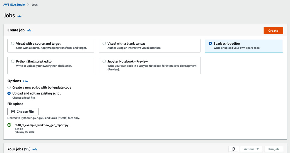
Figure 10.6 – The view for creating a Glue job in AWS Glue Studio
- After uploading the ch10_1_example_workflow_gen_report.py, click Create.
- Type ch10_1_example_workflow_gen_report as the job’s name and choose your IAM Role for running the Glue job.
- Scroll down the page and set Requested number of workers to 3, Job bookmark to Disable, and Number of retries to 0.
- Then, set each of your S3 bucket paths, using the details shown in the following screenshot:
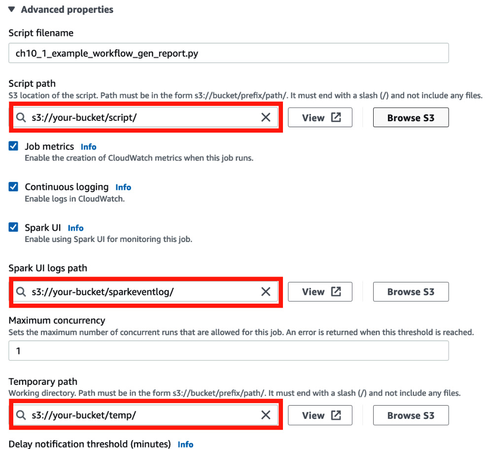
Figure 10.7 – Setting a script, Spark event logs, and temporary locations
- Scroll down the page and set s3://crawler-public/json/serde/json-serde.jar to Dependent JARs path.
- Save the job.
Now that you’ve created the data pipeline, you will create a workflow by using the crawler and glue job you created.
Step 2 – creating a workflow
Let’s create a workflow that will manage the crawler and ETL job that you created in Step 1 – creating a data pipeline with a Glue crawler and an ETL job. Follow these steps:
- Open Workflows in the AWS Glue console (https://console.aws.amazon.com/glue/home?region=us-east-1#etl:tab=workflows;workflowView=workflow-list) and click Add workflow.
- Set ch10_1_example_workflow_gen_report as the workflow’s name and set the following workflow run properties:
- Key: datalake_location, Value: s3://<your-bucket-and-path>; this is the report data S3 path.
- Key: database, Value: <the db name which you set to the Crawler you created in Step 1>; this is the table of the Amazon Customer Review dataset.
- Key: table, Value: example_workflow_sales; this table is created by the crawler and its name is set to this value.
- Key: report_year, Value: 2021; In this example, 2021 is set as the value.
- Then, click Add workflow at the bottom of the page.
- After adding the workflow, you can create a Glue trigger to run your workflow. Click Add trigger:
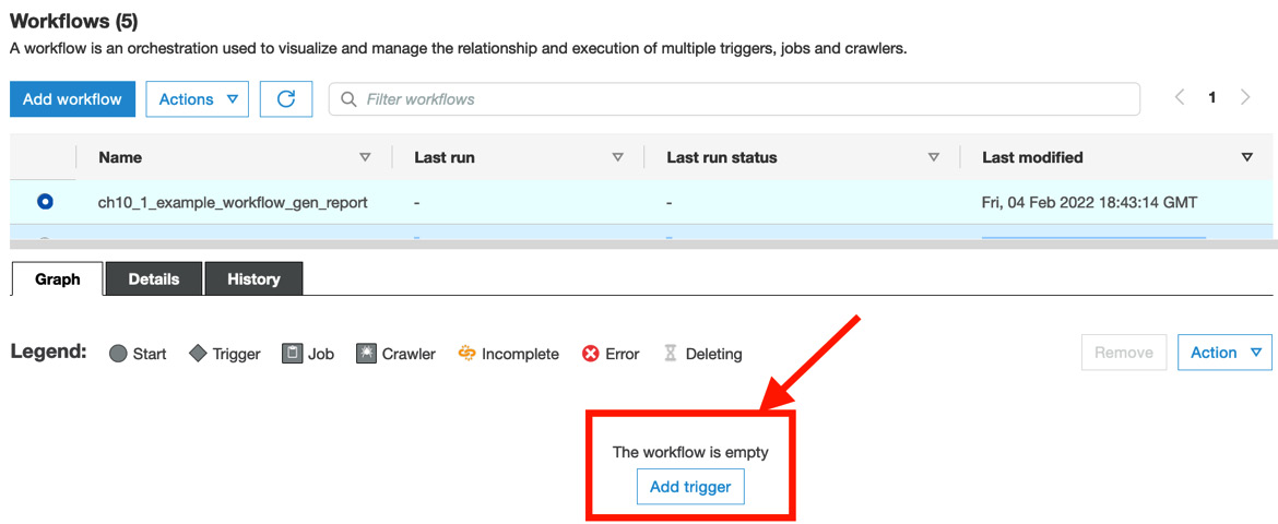
Figure 10.8 – Adding a trigger to the workflow
- Go to the Add new tab, type ch10_1_example_workflow_ondemand_start as the workflow’s name, and set On demand for Trigger type. Then, click Add.
- At this point, you will be able to see the first trigger in the Graph tab. Let’s add the Crawler first. Click Add node, as shown in the following screenshot:
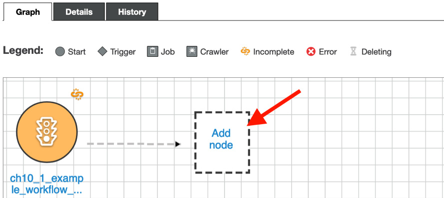
Figure 10.9 – Adding a node to the workflow
- Go to the Crawlers tab, specify the ch10_1_example_workflow crawler, and click Add.
- You will see the crawler in your workflow diagram. Now, create a new trigger to run the ETL job. Click Add trigger in the workflow diagram.
- In the Add new tab, type ch10_1_example_workflow_event_gen_report as a new trigger name. Set Event as its trigger type and Start after ALL watched event as its trigger logic. Then, click Add.
- The following screenshot shows the additional trigger that starts running ETL jobs. To set the job for this trigger, click Add node:
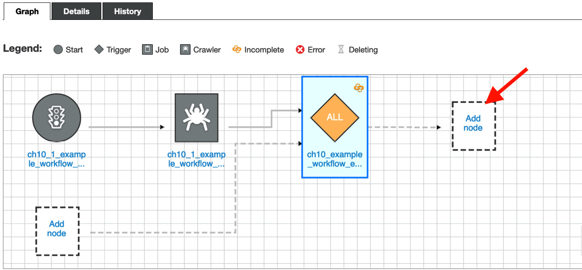
Figure 10.10 – Adding a new Glue job node to the workflow
- Go to the Jobs tab, specify the ch10_1_example_workflow_gen_report job, and click Add.
Once you’ve configured the workflow, you will see the following diagram in the Graph tab:
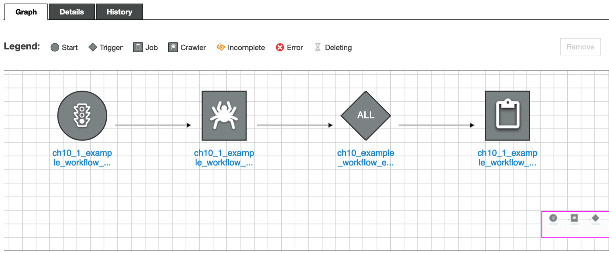
Figure 10.11 – The workflow diagram
Now, you’re ready to run the workflow! This is what we’ll do in the next step.
Step 3 – running the workflow
You can run the workflow via the Glue console. Follow these steps:
- Go back to the workflow in the Glue console and choose your workflow (ch10_1_example_workflow_gen_report). Then, choose Actions and click Run.
- After starting the workflow, you can see the workflow’s running status by going to View run details in the History tab.
- Once the workflow has finished running, you will see each node’s status, as shown in the following diagram (this workflow run may take around 4 or 5 minutes):
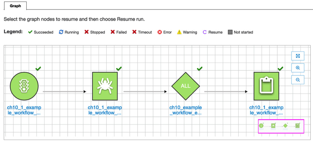
Figure 10.12 – The completed graphical workflow
The workflow run is now completed. Finally, let’s check the result.
Step 4 – checking the result
By running this workflow, two tables were created by the crawler and the ETL job, and the reviews count report was provided as output in the S3 bucket you specified as datalake_location in Step 2 – creating a workflow. Let’s have a look at these resources:
- The two tables that were created (you can see these tables in the Glue Data Catalog at https://console.aws.amazon.com/glue/home#catalog:tab=tables):
- example_workflow_sales: This was created by the crawler; that is, ch10_1_example_workflow. This table contains the table schema of the sales data.
- example_workflow_sales_report: This was created by the ETL job; that is, ch10_1_example_workflow_gen_report. This table has the table schema which includes, reported year as a partition key.
- The generated report data in the S3 bucket. The ETL job writes the report data in the S3 path as s3://<your-specified-bucket-and-path>/serverless-etl-and-analysis-w-glue/chapter10/example-workflow/report/. You can view the following bucket path and data by using the AWS CLI command:
$ aws s3 ls s3://<your-bucket-path>/serverless-etl-and-analysis-w-glue/chapter10/example-workflow/report/ --recursive
YYYY-MM-dd 01:23:45 799 <path>/serverless-etl-and-analysis-w-glue/chapter10/example-workflow/report/report_year=2021/run-xxxxxxxxxx-part-block-0-0-r-00113-snappy.parquet
- The ETL job output in the CloudWatch logs. You can access the log link from the Glue Studio console by choosing Output logs in the Runs tab. The page will redirect you to the CloudWatch Logs console. Choose the Spark driver task ID that doesn’t have an underscore (_) in the name of the Log stream; that is, jr_ea5565f6e248aa49dbbb….
You will see the following generated report. This report shows the product sales by each category in 2021:
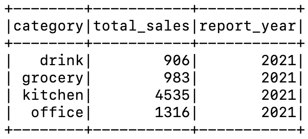
Figure 10.13 – The Glue job’s output in the Spark driver task log
In this section, we’ve done the following:
- Created a pipeline that is composed of a crawler and an ETL job:
- The crawler populates a table in the Data Catalog
- The ETL job generates a report by referring to the table data
- Created the workflow, which consists of two triggers for running the crawler and the ETL job. This workflow runs each component in the pipeline.
- Run the workflow and checked the result.
In this example, we learned that Glue workflows allow you to run data pipelines that consist of multiple crawlers and jobs. However, you may think that it’s a bit hard to build multiple workflows that have multiple triggers/crawlers/ETL jobs because you need to set each component one by one. This can be solved by using provisioning tools such as AWS CloudFormation, Glue Blueprints, and so on. We’ll look at these tools in the Automating how you provision your pipelines with provisioning tools section. Next, we’ll look at another workflow tool: AWS Step Functions.
Using AWS Step Functions
AWS Step Functions is a serverless orchestration service that allows you to combine multiple AWS services such as AWS Lambda, AWS Glue, and so on. It can also be used to orchestrate and run multiple data pipelines, including multiple AWS data processing services and their related data storage. You can define workflows with Step Functions’ graphical console, which visualizes your workflows.
Step Functions consists of state machines and tasks. Let’s look at them in more detail:
- A state machine is a workflow.
- A task is a state (or a step) in a workflow. This state represents a single unit of work that’s performed by a state machine.
To define a Step Functions workflow, you must create a state machine that has and combines multiple tasks, such as invoking a Lambda function, starting a Glue job run, running an Athena query, and so on.
Step Functions can handle AWS Glue APIs and you can create ETL workflows via Step Functions. Next, we’ll orchestrate the same data pipeline that we built in the previous Glue workflows example by building a workflow with Step Functions.
Example – orchestrating the pipeline that extracts data and generates a report using Step Functions
In this example, we’ll create the same data pipeline that we did in the Example – orchestrating the pipeline that extracts data and generates a report using Glue workflows section. Then, we’ll orchestrate the pipeline with Step Functions’ workflow. This pipeline will generate a product sales report by computing sales by each product category and year.
The Step Functions’ workflow runs the pipeline by doing the following:
- Step Functions’ workflow triggers the crawler (ch10_2_example_workflow_acr), which analyzes a table schema of the sales data and populates a table in Glue Data Catalog.
- After starting the crawler, the workflow polls the crawler’s running status. If it confirms that the crawler has finished running, it triggers the ETL job (ch10_2_example_workflow_gen_report), which generates a report by computing sales by each product category and year. Then the job populates the report table in the Data Catalog.
First, let’s create the pipeline.
Step 1 – creating a data pipeline with a Glue crawler and an ETL job
In this example, we’ll create the crawler and the ETL job. These will have the same configuration as the crawler (ch10_1_example_workflow) and ETL job (ch10_1_example_workflow_gen_report) we created in the Example – orchestrating the pipeline that extracts data and generates a report using Glue workflows section. If you haven’t created the crawler and ETL job, please refer to that section. Follow these steps:
- Go to Crawlers (https://console.aws.amazon.com/glue/home?region=us-east-1#catalog:tab=crawlers) in the AWS Glue console and choose ch10_1_example_workflow. Then, choose Duplicate crawler from the Action tab.
- Type ch10_2_example_workflow as the crawler’s name and choose Output in the left pane.
- In the crawler’s Output view (in the left pane), type example_workflow_sfn_ in Prefix added to tables (optional) for the table.
- After reviewing the crawler’s configuration, click Finish.
- Next, you must create the Glue job. Before creating the job, download the Glue job script from this book’s GitHub repository (https://github.com/PacktPublishing/Serverless-ETL-and-Analytics-with-AWS-Glue/blob/main/Chapter10/workflow-tools/step-functions/ch10_2_example_workflow_gen_report.py).
- Open the job in the AWS Glue Studio console (https://console.aws.amazon.com/gluestudio/home?region=us-east-1#/jobs). Then, choose the ch10_1_example_workflow_gen_report job and choose Clone job from the Actions tab to take over the previous job configuration.
- On the Job details tab, type ch10_2_example_workflow_gen_report as the job’s name. Confirm that the script’s filename is ch10_2_example_workflow_gen_report.py.
- On the Script tab, copy the downloaded job script to the editor. Then, click Save to save the job.
Next, we’ll create a Step Functions state machine by combining it with a Glue crawler and an ETL job.
Step 2 – creating a state machine
In this step, we’ll create a step machine that orchestrates a Glue crawler and an ETL job:
- Before creating the job, download the state machine definition from this book’s GitHub repository (https://github.com/PacktPublishing/Serverless-ETL-and-Analytics-with-AWS-Glue/blob/main/Chapter10/workflow-tools/step-functions/ch10_2_example_sfn.json).
- Open the AWS Step Functions console (https://console.aws.amazon.com/states/home#/statemachines) and click Create state machine.
- On the Define state machine page, click Write your workflow in code and then Standard in the Type section. Then, copy the downloaded definition to the script editor (by clicking the Reload button, you can see the visualized workflow, as shown in the following screenshot). After copying the script, click Next:
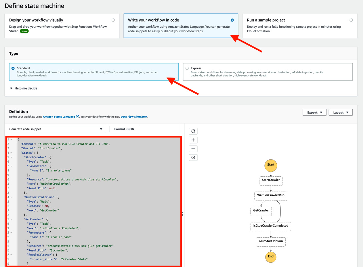
Figure 10.14 – Defining the state machine
As we’ve discussed, this state machine polls the crawler’s running status periodically (every 20 seconds). After that, the state machine starts the ETL job.
- On the Specify details page, type ch10_2_example_workflow_sfn as the state machine’s name and click Create new role (the IAM Role that includes the necessary permission is created by AWS). Regarding the Logging section, by default, logging configuration is not enabled. If necessary, you can set any log level such as ALL, ERROR, and so on.
When you scroll down the page, you may see a notification about insufficient permissions that states “Permissions for the following action(s) cannot be auto-generated ….” After creating the state machine, we’ll add these permissions to the IAM Role.
- Click Create state machine. Upon doing this, the state machine you defined will be created.
- To add the insufficient permission to the IAM Role for the state machine, open the IAM console (https://console.aws.amazon.com/iamv2/home#/policies) and create a new IAM policy. Copy the policy file in this bok’s GitHub repository (https://github.com/PacktPublishing/Serverless-ETL-and-Analytics-with-AWS-Glue/blob/main/Chapter10/workflow-tools/step-functions/ch10-2-sfn-additional-glue-policy.json). After creating the policy, attach it to the IAM Role.
Now, you’re ready to run the workflow. We’ll do this in the next section via the Step Functions console.
Step 3 – running the state machine
Let’s run the workflow. In this step, we’ll run it manually from the Step Functions console. You can also invoke the state machine via the StartExecution API (https://docs.aws.amazon.com/step-functions/latest/apireference/API_StartExecution.html). Follow these steps:
- Go back to the Step Functions console, choose the ch10_2_example_workflow_sfn state machine, and click Start execution.
- Specify the following input to the state machine. You can copy the input from this book’s GitHub repository: https://github.com/PacktPublishing/Serverless-ETL-and-Analytics-with-AWS-Glue/blob/main/Chapter10/workflow-tools/step-functions/ch10_2_input.json. Note that we need to replace the values of --datalake_locaiton and --table. These parameters are processed by the state machine and passed to the ETL job as job parameters:
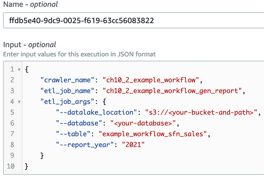
Figure 10.15 – The input to the state machine
- After starting the execution, you will be able to see the running status of each task. Once the execution has finished, you will see the following diagram:
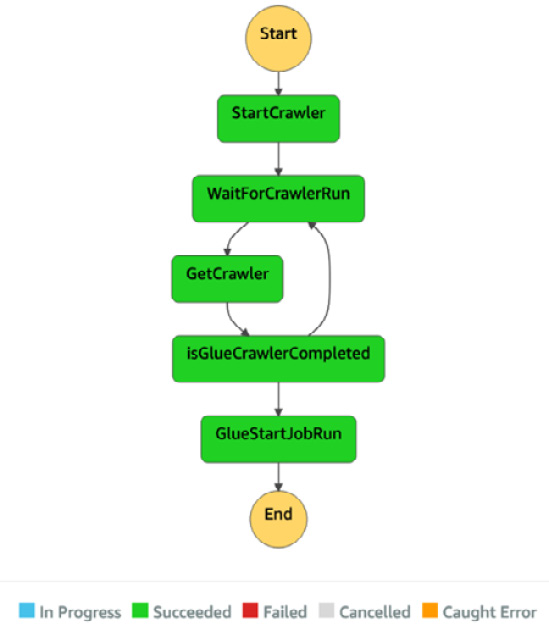
Figure 10.16 – The completed workflow diagram
Now, let’s check out the result of executing the workflow.
Step 4 – checking the result
Here, we get the same result that we got in the Orchestrating the pipeline that extracts data and generates a report by Glue workflows section. Therefore, we won’t look at the result in detail here, but we will look at the output:
- Two tables were created in the Data Catalog:
- example_workflow_sfn_sales: This was created by ch10_1_example_workflow crawler.
- example_workflow_sfn_sales_report: This was created by the ch10_2_example_workflow_gen_report job.
- The report data was generated in the S3 path as s3://<your-specified-bucket-and-path>/serverless-etl-and-analysis-w-glue/chapter10/example-workflow-sfn/report/.
- The ETL job’s output shows the sales data of each category and year in CloudWatch Logs. You can access this log from the Glue job, as we’ve seen previously.
In this example, we learned that Step Functions also provides running data pipelines that consist of multiple crawlers and jobs, similar to what Glue workflows provide. Using Step Functions, you can manage your workflows using a JSON-like template. This can make it easier to build and manage workflows compared to manually creating workflows via a GUI application because all you need to do is manage your templates.
Step Functions supports not only AWS Glue but also other AWS services such as AWS Lambda, Amazon Athena, and others. By using Step Functions, you can create various workflows by combining multiple AWS services.
Now, let’s look at Amazon Managed Workflows for Apache Airflow (MWAA) one of many available workflow tools.
Using Amazon Managed Workflows for Apache Airflow
MWAA is a distributed orchestration service that provides programmatic workflow management. MWAA is based on Apache Airflow (https://airflow.apache.org), whose resources are managed by AWS. Airflow runs workflows that are expressed as DAGs, as defined by Python. By defining workflows as DAGs, Airflow orchestrates and schedules your workflows. We won’t explain the details of Airflow in this book, but you can refer to the public Airflow documentation if you want to learn more: https://airflow.apache.org/docs/apache-airflow/stable/concepts/index.html.
You can use MWAA to create workflows that combine not only AWS Glue but also other AWS services, such as Amazon Athena, Amazon EMR, and others. Next, we’ll learn how to combine MWAA with AWS Glue by creating the same workflow that we created in the previous two examples.
Example – orchestrating the pipeline that extracts data and generates a report using MWAA
In this example, you’ll learn how to use MWAA as a workflow tool for Glue by creating the same workflow and pipeline that you created for Glue workflows and Step Functions. In the workflow, MWAA runs a crawler. After completing the crawler run, it starts an ETL job. If you haven’t set up the MWAA environment yet, please refer to https://docs.aws.amazon.com/mwaa/latest/userguide/get-started.html (this document link is also provided in the Technical requirements section).
Step 1 – creating a data pipeline with a Glue crawler and an ETL job
First, download the Glue job script from this book’s GitHub repository at https://github.com/PacktPublishing/Serverless-ETL-and-Analytics-with-AWS-Glue/blob/main/Chapter10/workflow-tools/mwaa/ch10_3_example_workflow_gen_report.py. The crawler and the ETL job that you will create here will be the same ones that you created in Step 1 – creating a data pipeline with a Glue crawler and an ETL job in the Example – orchestrating the pipeline that extracts data and generates a report using Glue workflows section. You’ll create the following resources with updating configuration:
- Crawler (ch10_3_example_workflow): Create this crawler by replicating ch10_2_example_workflow_acr crawler. Update the table prefix that the crawler creates from example_workflow_sfn_ to example_workflow_mwaa_.
- ETL job (ch10_3_example_workflow_gen_report): Create this job by copying the ch10_2_example_workflow_gen_report job. Update the job script from ch10_2_example_workflow_gen_report.py to ch10_3_example_workflow_gen_report.py (this can be downloaded from the aforementioned GitHub repository).
Now that you’ve created the crawler and job, you must set up the workflow via MWAA.
Step 2 – creating a workflow with MWAA
To create and run the DAG, you need to upload the DAG file that’s been written in Python to the S3 bucket that is specified for your MWAA environment. The DAG file (ch10_3_example_workflow_dag.py) can be downloaded from this book’s GitHub repository at https://github.com/PacktPublishing/Serverless-ETL-and-Analytics-with-AWS-Glue/blob/main/Chapter10/workflow-tools/mwaa/ch10_3_example_workflow_dag.py. After downloading it, upload it to the DAG location in your S3 bucket.
After uploading the DAG file, you will see the ch10_3_example_workflow_mwaa workflow from Airflow UI. Now, you can trigger this workflow by using the Trigger button in the Actions column in the Airflow UI.
Step 3 – checking the result
After running the workflow, you will see the following DAG execution result from the Airflow UI. In particular, you will see if the DAG was successful or not, as well as concrete components such as the sales_crawl task (which is ch10_3_example_workflow crawler-run) and gen_report (which is ch10_3_example_workflow_gen_report job-run):
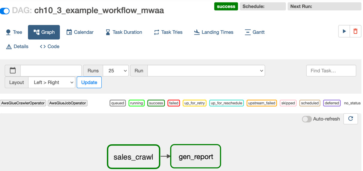
Figure 10.17 – The DAG’s execution result in Airflow UI
You will also see each of the component’s results, as follows:
- The example_workflow_mwaa_sales table is created by the sales_crawl task.
- The example_workflow_mwaa_sales_report table is created by the gen_report task.
- The gen_report task also writes the data in your specified S3 path.
By walking through this basic example, you’ve learned that you can also use MWAA as a workflow tool for Glue. Using MWAA, you can programmatically manage your workflows with Python. This can also make it easier to build and manage workflows compared to manually creating them. Additionally, you can provision workflows more safely by adding testing code steps (such as unit tests, integration tests, and so on) to your development life cycle.
As Step Functions does, MWAA supports not only Glue but also other AWS services, such as Amazon Athena, Amazon EMR, and others. You can find more examples of creating workflows, including Glue by MWAA in the AWS Glue public document and AWS big data blog posts. If you’re interested in this example, please refer to the Further reading section at the end of this chapter.
As you’ve seen, several workflow tools, such as Glue workflows, Step Functions, and MWAA, can run your pipeline components step by step based on your workflow’s definition, such as scheduling, on-demand, and so on. However, you need to create pipeline components before building and running workflows. If you need to create pipelines that consist of a lot of components, it’s not easy to manually create, update, and replicate the pipelines, which you did in each of the preceding examples. To make these operations easy, you can use another tool that builds resources on your behalf. This tool is generally called provisioning tools. We’ll look at this in the next section.
utomating how you provision your pipelines with provisioning tools
In the previous section, Orchestrating your pipelines with workflow tools, you learned how to orchestrate multiple pipelines and automate how they run with one tool. Using workflow tools for multiple pipelines can not only avoid human error but can also help you understand what pipelines do.
Note that as your system grows, you will build a lot of pipelines, and then you will build workflows to orchestrate them. If you have a lot of workflows as your system grows, you may need to consider how you should manage them. If you manually build several workflows and deploy them on your system, similar to how you would build and run pipelines manually, you may build some workflows that contain bugs. You can do this by specifying incorrect data sources, connecting incorrect pipeline jobs, and so on. As a result, this will corrupt your data and system, and pipeline job failures will occur due to broken workflows being deployed.
So, how can you avoid these kinds of errors when building workflows? One of the solutions involves using provisioning tools such as AWS CloudFormation (https://aws.amazon.com/cloudformation/), AWS Glue Blueprints (https://docs.aws.amazon.com/glue/latest/dg/blueprints-overview.html), Terraform (https://www.terraform.io), which is provided by Hashicorp, and others.
Provisioning tools generally deploy resources defined in the template, which you specify as JSON, YAML, and so on. Here’s a simple example template of AWS CloudFormation, which creates the glue_db database and then the glue_table table in your Glue Data Catalog:
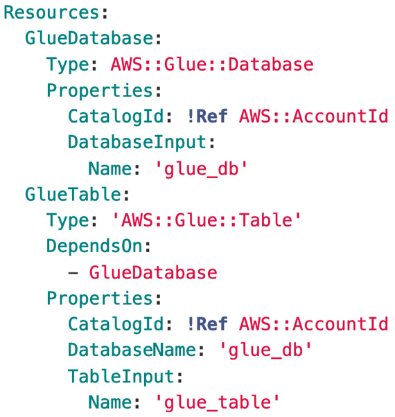
Figure 10.18 – An example of a CloudFormation template
As mentioned previously, in this example, by using provisioning tools, you can manage your pipelines and workflows as a template that’s in JSON, YAML format, and so on. In addition to this, there are provisioning tools that allow you to define and manage your pipelines and workflows as code. For example, you can define your data pipelines with popular programming languages, and you can also safely deploy them by running your resource definition code. AWS Glue provides this programmatic resource definition functionality via AWS Glue Blueprints. Other tools are provided by AWS for this purpose, such as AWS Cloud Development Kit (AWS CDK), which automatically creates CloudFormation templates based on your code.
In this section, you’ll learn how to build and manage your workflows and pipelines with provisioning tools. Specifically, we’ll focus on the following two services, which are provided by AWS:
- AWS CloudFormation
- AWS Glue Blueprints
First, we’ll look at AWS CloudFormation.
Provisioning resources with AWS CloudFormation
AWS CloudFormation allows you to model and set up AWS resources with a template where you define the necessary resources. CloudFormation mainly provides the following features for users:
- Simplifying your resource management: All you need to do is create or update a template. Based on this template, CloudFormation sets up resources for your environment on your behalf.
- Quickly replicating your resources: Once you have defined a template, by reusing it, you can create or update your resources over and over.
- Controlling and tracking changes in your resources: By defining your resources as a text-based file (we’ve been calling this a template), you can control and track your resources.
You can define the resources that you want to deploy, and related resource properties in a template in JSON or YAML format. In CloudFormation, defined resources in a template are handled as a single unit. This unit is called a stack. If you want to change your running resources and update a stack, you can create sets of your proposed changes before making changes to them. These sets are called change sets. They allow you to see how your running resources change before you update them.
By using CloudFormation for your data pipelines, you can build data pipeline resources such as data processing services, workflows, and more with a template. Additionally, CloudFormation can track changes in your pipeline resources. Once you have defined data pipelines and workflows in a template, you don’t need to manually create or update pipelines with GUI tools. Therefore, CloudFormation helps not only easily provision resources but also avoid human error, such as workflow misconfiguration and incorrectly setting data processing engines.
CloudFormation covers a lot of AWS services, including Glue. Through a template, you can set up Glue resources such as databases, tables, crawlers, jobs, and more. To learn more about the Glue resources that CloudFormation covers, please refer to https://docs.aws.amazon.com/glue/latest/dg/populate-with-cloudformation-templates.html.
Now, let’s learn how to set up a schedule-based data pipeline that consists of Glue ETL jobs and Glue workflows by defining resources in a CloudFormation template.
Example – provisioning a Glue workflow using a CloudFormation template
In this example, you will extend the data pipeline that you created in the Orchestrating your pipelines with workflow tools section. In particular, you will provision the ch10_4_example_cfn_ Glue workflow by CloudFormation (this workflow has been omitted in each component name in the following diagram). This workflow runs each component in the pipeline as follows:
- The ondemand_start component triggers the acr crawler, which populates a table based on the sales data.
- After crawler-run is completed, event_run_partitioning triggers the partitioning job. This job extracts the data from the Amazon Customer Reviews dataset and writes the data to the S3 path with year and month-based partitioning.
- Once the partitioning job has finished running, event_run_gen_report triggers the gen_report job. This job generates the same report that the job in the Orchestrating your pipelines with workflow tools section did:
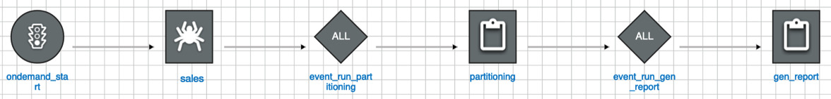
Figure 10.19 – The Glue workflow graph you’ll create via CloudFormation
Let’s create this workflow using CloudFormation.
Step 1 – putting ETL job scripts in your S3 bucket
Before provisioning the resources via CloudFormation, copy the necessary job scripts to your S3 bucket by using the S3 console or the aws s3 cp <your_local_script_location> s3://<your-bucket-and-path>/ AWS CLI command. You can download these job scripts from the following GitHub repository links:
- https://github.com/PacktPublishing/Serverless-ETL-and-Analytics-with-AWS-Glue/blob/main/Chapter10/provisioning-tools/cloudformation/ch10_4_example_cf_partitioning.py
- https://github.com/PacktPublishing/Serverless-ETL-and-Analytics-with-AWS-Glue/blob/main/Chapter10/provisioning-tools/cloudformation/ch10_4_example_cf_gen_report.py
Next, you’ll provision the crawler, ETL jobs, and workflow.
Step 2 – provisioning triggers, the crawler, ETL jobs, and the workflow via a CloudFormation template
You can provision the resources in this book’s GitHub repository with a CloudFormation template (https://github.com/PacktPublishing/Serverless-ETL-and-Analytics-with-AWS-Glue/blob/main/Chapter10/provisioning-tools/cloudformation/ch10_4_example_cf.yml). Follow these steps:
- Open the CloudFormation console (https://console.aws.amazon.com/cloudformation/home) and click Create stack, then With new resources (standard), at the top right of the page.
- Choose Template is ready and upload your downloaded YAML file (ch10_4_example_cf.yml).
- Follow each description and type in the necessary information. Then, click Next so that you can provision the resources. It will take a few minutes to create resources via the CloudFormation stack:
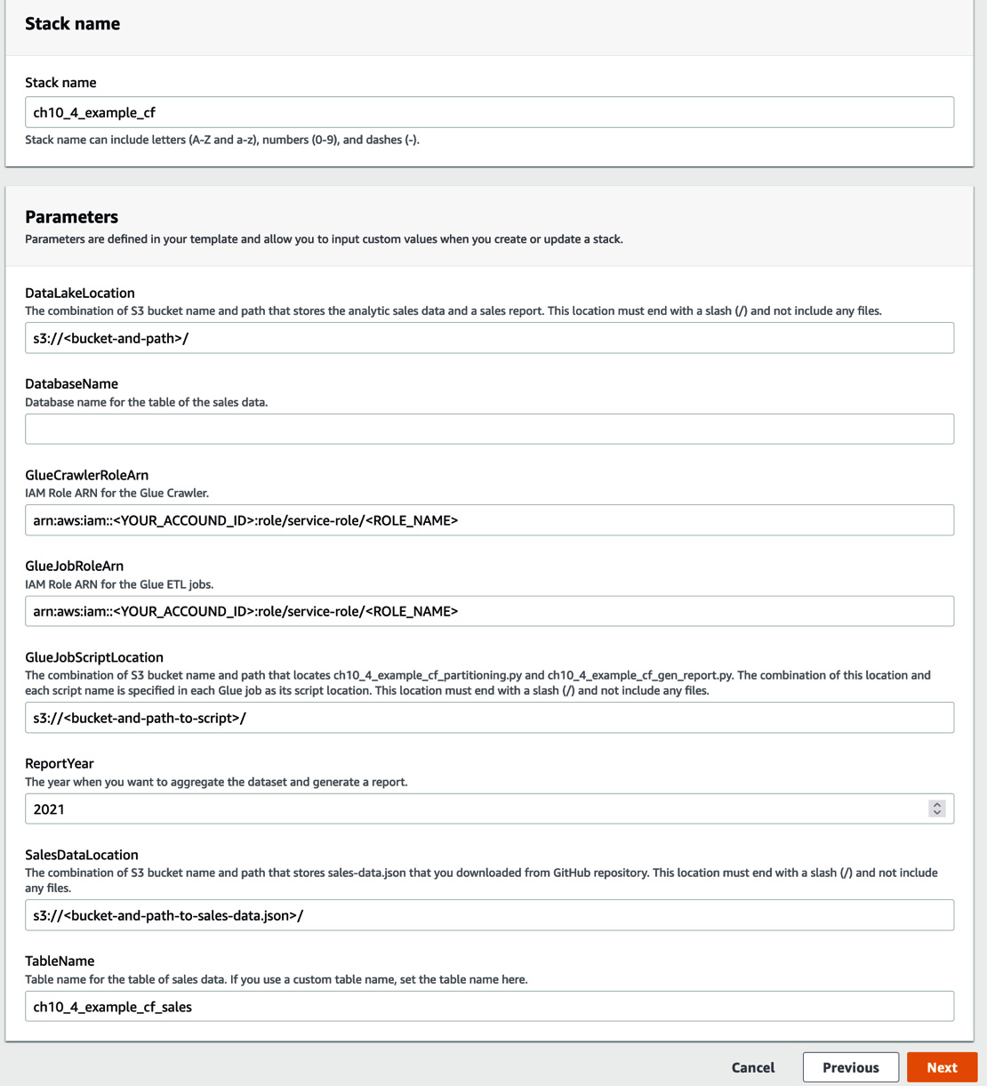
Figure 10.20 – The AWS Management console view for filling in parameters
- Once resource provisioning has been completed, the stack’s status will appear as CREATE_COMPLETE on the CloudFormation console.
Next, you will check the provisioned resources.
Step 3 – checking the provisioned resources
You will see the following resources that have been provisioned by the CloudFormation stack on the Glue console:
- Triggers:
- ch10_4_example_cf_ondemand_start
- ch10_4_example_cf_event_run_partitioning
- ch10_4_example_cf_event_run_gen_report
- Crawler: ch10_4_example_cf
- ETL jobs:
- ch10_4_example_cf_partitioning
- ch10_4_example_cf_gen_report
- Workflow: ch10_r_example_cf
This workflow visualizes the same diagram as the one shown in Figure 10.43.
You can also run this workflow by choosing Run from the Actions menu in the Glue console (https://console.aws.amazon.com/glue/home#etl:tab=workflows). In addition to the same generated reports that we got in the previous section, the pipeline also replicates the Amazon Customer Reviews dataset to the S3 bucket that you specified as the CloudFormation stack parameter. In particular, you will be able to see the replicated files by using the following AWS CLI command:
$ aws s3 ls s3://<your-bucket-and-path>/serverless-etl-and-analysis-w-glue/chapter10/example-cf/data/ --recursive
YYYY-MM-dd 01:23:45 XXXX <path>/serverless-etl-and-analysis-w-glue/chapter10/example-cf/data/category=grocery/year=2021/month=6/run-xxxxxxxxxx-part-block-0-0-r-xxxxx-snappy.parquet
In this example, you learned that CloudFormation helps with the resource provisioning process. If you create that workflow and pipeline on the AWS Glue console, you need to create and configure at least seven components – that is, three triggers, one crawler, two ETL jobs, and this workflow. Additionally, if you try to replicate this workflow too many times, the process will be difficult (for example, if you replicate this into 10 workflows, you need to set up at least 70 components). However, if you create a CloudFormation template and create resources using that template, it becomes easier to set up multiple workflows compared to setting up each workflow manually from the Glue console.
You can find more examples of Glue resource provisioning by CloudFormation in the AWS Glue public document and AWS big data blog posts. If you’re interested in such examples, please refer to the Further reading section at the end of this chapter.
Provisioning AWS Glue workflows and resources with AWS Glue Blueprints
AWS Glue Blueprints allows you to create and share AWS Glue workflows by defining your workflow as a single blueprint, which is similar to using a template. In particular, you can build pipelines by specifying Glue ETL jobs, a crawler, and related parameters that are passed to your Glue jobs, crawlers, workflows, and so on in your blueprint. Based on a blueprint, Glue Blueprints automatically generate workflows. Therefore, you don’t need to manually set up workflows from the AWS Glue console.
To create a blueprint, you need to define the following components and package them as a ZIP archive file:
- A layout file implemented by Python: You can define crawlers, ETL jobs, and the relevant workflow, including your pipeline logic, in this file. When the layout file is run by Glue, your defined workflows are returned and generated.
- A configuration file: You need to set the function name that returns workflows and is defined in the layout file. You can set relevant workflow components such as the workflow names, data types, user input properties, and so on.
- ETL job scripts and the relevant files (optional): Here, you can specify the location of your ETL job scripts to create them and specify the relevant files in the layout to process them.
Let’s look at a basic example of a blueprint that consists of a layout file (layout.py) and a configuration file (blueprint.cfg). By applying this blueprint for Glue, the workflow that contains an ETL job, sample_etl_job_bp, will be created. The job’s configuration, such as the Glue job’s script location, Glue job role, worker type, and so on, is set by the implementation in the layout.py file. Additionally, you can set any Glue job script location by parameterizing the script location that’s defined in ScriptLocation, in parameterSpec, in blueprint.cfg.
The following code shows the Glue workflow and component definitions in layout.py:
def generate_layout(user_params, system_params):
etl_job = Job(
Name=»sample_etl_job_bp",
Command={«Name»: «glueetl",
«ScriptLocation": user_params['ScriptLocation'],
«PythonVersion": "3"},
Role=»your_glue_job_role",
WorkerType="G.1X",
NumberOfWorkers=5,
GlueVersion="3.0")
return Workflow(Name="sample_worflow_bp", Entities=Entities(Jobs=[etl_job]))
The following code shows the Glue workflow parameter configuration in blueprint.cfg:
{«layoutGenerator": "project.layout.generate_layout",
«parameterSpec": { «ScriptLocation": {«type»: «S3Uri»,
«collection»: false,
«description»: «Specify the S3 path to store your glue job script.»
}
}
}
After creating a workflow with this blueprint, you will be able to see the workflow in the AWS Glue console, as shown in the following screenshot:
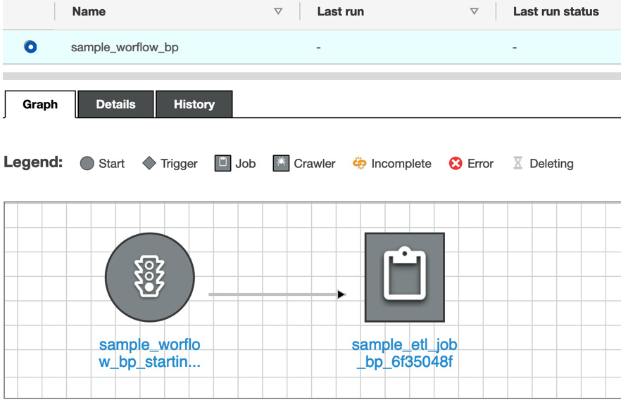
Figure 10.21 – A workflow that includes an ETL job generated by a blueprint
Using Glue Blueprints, you can easily create, replicate, and manage your workflow by implementing a layout file with Python and a configuration file with JSON. The AWS Glue public document (https://docs.aws.amazon.com/glue/latest/dg/blueprints-overview.html) shows what Glue Blueprints is, as well as what your job role needs to do based on three patterns of personas, such as Developer, Administrator, and Data Analyst. Next, you will set up the scheduled-based workflow that you tried to set up in the Provisioning a Glue workflow using a CloudFormation template section. You will do so by implementing a blueprint that includes a layout file and the necessary configuration.
Example – provisioning a Glue workflow using Glue Blueprints
In this example, by using Glue Blueprints, you will build the same workflow and pipeline that you did in the Provisioning a Glue workflow using a CloudFormation template section. In particular, the following resources will be provisioned via Glue Blueprints:
- Workflow: ch10_5_example_bp: This generates a report by running the necessary crawler and ETL jobs
- Triggers:
- Crawler: ch10_5_example_bp: This populates a table based on the Amazon Customer Reviews dataset
- ETL jobs:
To create and provision those resources, complete the following steps.
Step 1 – downloading and uploading the blueprint package
Download the ZIP-archived package from this book’s GitHub repository: https://github.com/PacktPublishing/Serverless-ETL-and-Analytics-with-AWS-Glue/blob/main/Chapter10/provisioning-tools/blueprints/chapter10_5_example_bp.zip. This package includes the following layout, configuration, and relevant job scripts. You can also view the content of each script in this book’s GitHub repository (https://github.com/PacktPublishing/Serverless-ETL-and-Analytics-with-AWS-Glue/tree/main/Chapter10/provisioning-tools/blueprints/scripts):
- layout.py
- blueprint.cfg
- ch10_5_example_bp_partitioning.py
- ch10_5_example_bp_gen_report.py
In this example, the two job scripts (ending with .py) are copied to the S3 location that you specify with layout.py. After downloading the ZIP package, upload it to your S3 bucket.
Step 2 – provisioning triggers, the crawler, ETL jobs, and the workflow via the blueprint
Now, you’re ready to provision the resources. First, you need to set up the blueprint. Follow these steps:
- Access Blueprints in the Glue console (https://console.aws.amazon.com/glue/home#etl:tab=blueprints) and click Add blueprint.
- Type ch10_5_example_bp as the blueprint’s name and specify the S3 path where you uploaded the package. Then, click Add blueprint.
Once the blueprint’s status is active, you must create the workflow. Follow these steps:
- Click Create workflow on the Blueprints page.
- Type in the necessary information, as shown in the following screenshot. Then, click Next so that you can provision the resources. After that, click Submit:
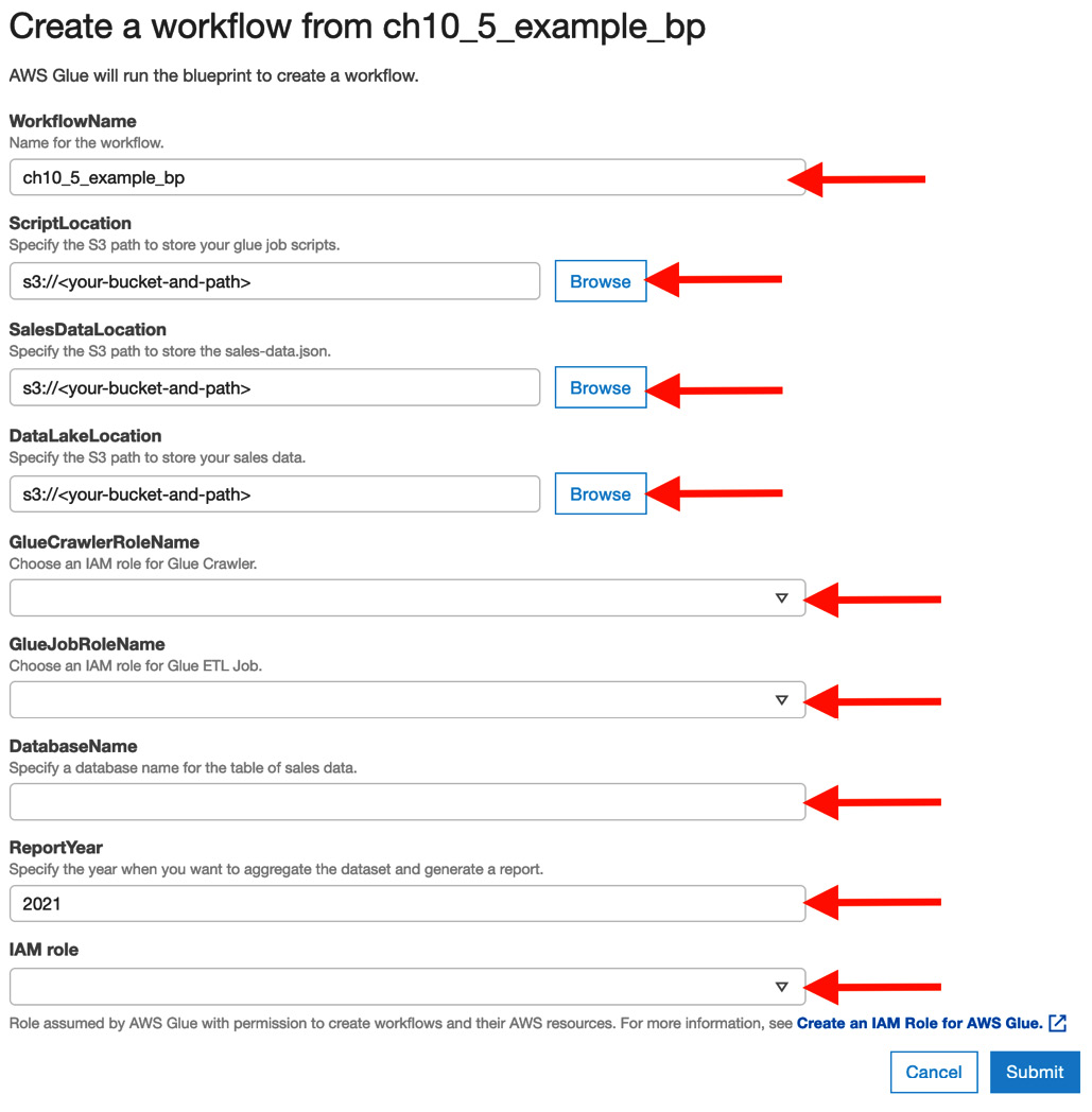
Figure 10.22 – Workflow configuration
- Once the blueprint successfully creates the ch10_5_example_bp workflow, go to View in the Actions menu in the Blueprints console. You will see the following output:
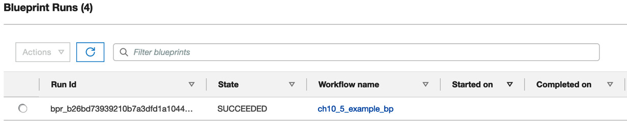
Figure 10.23 – Blueprint run status
Next, you will check the provisioned resources.
Step 3 – checking the provisioned resources
First, you can check the resources that have been created – that is, the workflow, triggers, the crawler, and the ETL jobs. The workflow visualizes the same graph as the one shown in Figure 10.43.
You can also run this workflow in the Glue console (https://console.aws.amazon.com/glue/home#etl:tab=workflows). Similar to what happened in the Provisioning a Glue workflow using a CloudFormation template section, the workflow replicates the Amazon Customer Reviews dataset to the specified S3 bucket and generates the report.
Blueprints also make provisioning resources easier than setting up resources manually from the Glue console. In addition to this basic example, you can try out more advanced examples by going to the GitHub repository provided by AWS: https://github.com/awslabs/aws-glue-blueprint-libs/tree/master/samples.
Developing and maintaining your data pipelines
Finally, let’s learn how to grow and maintain data pipelines. Your requirements and demands for data are always changing based on your company’s growth, market behaviors, business matters, technological shifts, and more. To meet the requirements and demands for data, you need to develop and update your data pipelines in a short period. Additionally, you need to care about the mechanism for detecting problems in your data pipeline implementations, safe pipeline deployment to avoid breaking your pipelines, and so on. For these considerations, you can apply the following system and concepts to your data pipeline development cycles. These are based on DevOps practices:
- Version control systems (VCSs): You can track changes, roll back code, trigger tests, and so on. Git is one of the most popular VCSs (more precisely, a distributed VCS).
- Continuous integration (CI): This is one of the software practices for building and testing all the changes on your system and integrating them only after successful tests.
- Continuous delivery (CD): This is similar to the concept of CI but is an extension of the concept. CI is usually for a single code base, while CD is for your systems. CD aims to continuously check if components, systems, and infrastructures have been prepared for production. The deployment usually needs explicit approvals. Sometimes, the deployment process is automated, which means that committed changes are instantly deployed on production after all tests are successfully passed. This automatic deployment is called continuous deployment.
There are a lot of references to deployment pipelines (NOT data pipelines), including the CI/CD process, such as about what CI/CD is, how to build CI/CD pipelines, and so on. Furthermore, actual deployment pipelines depend on company, organization, team, and system environments. Therefore, we won’t cover the deployment process in this section. However, we will look at the basic development process of data pipelines by focusing on AWS Glue and the related tools we’ve seen so far:
- Developing AWS Glue ETL jobs locally
- Deploying your AWS Glue ETL jobs
- Deploying your workflows and pipelines using provisioning tools such as Infrastructure as Code (IaC)
First, you will learn how to develop Glue ETL jobs locally.
Developing AWS Glue ETL jobs locally
AWS Glue provides various local development environments for effectively coding Glue ETL job scripts. You can use various environments for your local development. Let’s take a look at each module quickly:
- AWS Glue ETL Library: You can download the ETL library on your desktop and develop Glue ETL jobs using Python or Scala. The public documentation (https://docs.aws.amazon.com/glue/latest/dg/aws-glue-programming-etl-libraries.html) shows how to use the library.
- Docker images for Glue ETL: You can also use the ETL jobs with Docker images (https://hub.docker.com/r/amazon/aws-glue-libs) provided by AWS. At the time of writing, up to Glue 3.0 is supported. We won’t cover the steps to develop Glue ETL jobs with a Docker image, but you can refer to the concrete steps that use PyCharm by going to https://aws.amazon.com/blogs/big-data/developing-aws-glue-etl-jobs-locally-using-a-container/.
- Interactive Session: This is one of the Glue functionalities that allows you to develop Glue ETL jobs easily. You can interactively develop your ETL job scripts on Jupyter Notebook by connecting the Glue ETL job system. In the Glue Studio console, you can set up Jupyter Notebook and use it for development purposes. Furthermore, AWS Glue provides a Python module so that you can connect from your local desktop to the Glue job system and use the interactive session. You can install the module via pip from https://pypi.org/project/aws-glue-sessions/. Please refer to the public document for details about the setup steps: https://docs.aws.amazon.com/glue/latest/dg/interactive-sessions.html.
Note – Local Development Restrictions
When you use the local library, at the time of writing, the JobBookmarks, Glue parquet writer, and FillMissingValues/FindMatches transforms in Glue ML are not supported. You need to use them within the Glue job system.
Regarding the Glue ETL job development cycle, Interactive Session is one of the ways to start checking how you process data, how you can implement Glue job scripts, and so on. If you already have Jupyter Notebook, you can use it on the Glue Studio console by uploading it to the console. You can also use Glue ETL Library and Docker images for your Glue ETL jobs development cycle to write tests, implement code, commit changes, build a package, and more.
Next, you will learn how to deploy your developed Glue ETL job code in the Glue job system.
Deploying AWS Glue ETL jobs
In this section, you’ll learn how to deploy Glue ETL jobs by applying changes to your code base. When you initially create or update your ETL jobs, the following two styles are considered:
- Update your job scripts and relevant packages in the S3 location: In this style, you define the ETL jobs first. Then, you continuously update the scripts and packages in the S3 location that you specified as a script filename, Python library path, dependent Jars path, and/or reference files path in your ETL jobs.
- Deploy your Glue jobs: In addition to updating job scripts and packages, you can deploy your Glue job by using provisioning tools. We’ll look at this in the next section.
For both styles, you can create a CI/CD pipeline and make it take on the following challenges while developing ETL jobs:
- Continuous development with unit and integration tests
- Continuous integration and build
- Testing ETL jobs for actual (small) datasets
- Testing the quality of datasets
- Delivering ETL jobs in test and production environments
For these challenges, AWS provides developer tools (https://aws.amazon.com/tools/#DevOps_and_Automation) such as AWS CodeCommit, AWS CodePipeline, AWS CodeBuild, and others. You can build CI/CD pipelines by combining these tools. There is a variety of AWS-provided tools to help with the development process, but we will cover the ones mentioned previously as they are often used in the ETL jobs development process to create a basic pipeline. Let’s take a quick look at each tool and how to use it in the ETL jobs development process.
- AWS CodeCommit: This is an AWS-managed version control service. You can use it as a code repository to manage your job scripts using Git. CodeCommit can also integrate with other AWS tools such as AWS CodeBuild, AWS CodePipeline, AWS Lambda, and others.
- AWS CodeBuild: This is an AWS-managed build service. By using CodeBuild, you can compile your code, run tests, and create artifacts for deployment. CodeBuild covers various environments, such as operating systems (Amazon Linux 2, Ubuntu, and Windows Server 2019), programming language runtimes (Java and Python), build tools ( Apache Maven and Gradle), and so on. You can also specify your custom image as a build environment. CodeBuild supports not only CodeCommit as a source provider but also Amazon S3, GitHub, BitBucket, and more. You can build, test, and create an updated ETL job script in this process.
- AWS CodePipeline: This is an AWS-managed continuous delivery service. By defining release pipelines, CodePipeline automates the pipelines, including build, test, and deploy. For CodePipeline, you define the source, build, and deploy stages. For the source stage, you can specify your code repository and its branch, such as AWS CodeCommit, Amazon ECS, Amazon S3, GitHub, and so on. For the build stage, you can select AWS CodeBuild or Jenkins. For the deploy stage, you can select a deployment provider, such as AWS CloudFormation, AWS ECS, or Amazon S3. For example, if you select Amazon S3 as your deployment provider, CodePipeline delivers your job scripts in your ETL job’s S3 location. Then, you can run the updated job.
By using these tools, you can effectively develop Glue ETL jobs in a CI/CD pipeline.
Note – Data Quality Tests
AWS provides Deequ (https://github.com/awslabs/deequ), an open source data quality unit test tool. This tool checks whether your data is malformed or corrupted, and then computes quality metrics of your data. Please refer to the Managing data quality section in Chapter 6, Data Management, to learn how to use Deequ with Glue. If you wish to consider data quality tests for your data processing, please refer to the following blog post: https://aws.amazon.com/blogs/big-data/test-data-quality-at-scale-with-deequ/. This describes how to use it within Apache Spark.
Now, let’s learn how to deploy workflows and pipelines.
Deploying workflows and pipelines using provisioning tools such as IaC
In this section, you’ll apply the concept of the CI/CD pipeline for AWS Glue ETL jobs to the data pipelines and workflows you’ve developed. You can also manage the development process of your workflows, data pipelines, and relevant components such as Glue ETL jobs, Glue crawlers, and so on using CI/CD pipelines. In particular, you can use template-based workflows or provisioning tools to automatically deploy and manage your data processing infrastructure. This infrastructure management is based on IaC, which applies software development practices to infrastructure automation. By managing your infrastructure based on code, you can automate building or changing your infrastructure quickly and safely within CI, CD, and so on.
Regarding workflows and data pipelines, you can build, test, and deploy workflows and their relevant components in CI/CD pipelines by developing template-based files or provisioning tools such as AWS Step Functions, JSON templates, AWS CloudFormation, YAML templates, MWAA Python DAGs, Blueprint Python code, and more.
Let’s take a quick look at the example from the Provisioning AWS Glue workflows and resources with AWS Glue Blueprints section. There, you defined workflows, a crawler, and Glue ETL jobs in the same repository and deployed each component. Blueprints allows you to programmatically manage workflows and the relevant components. Therefore, you can manage workflows, crawlers, and ETL jobs in the same repository as a data pipeline resource. You can also add tests for Blueprints, not just ETL job scripts. Then, you can build, test, and deploy the Blueprints code and ETL job scripts at the same time in a CI/CD pipeline that contains your data processing infrastructure. This can make your development process safer and faster compared to manually validating your infrastructure code.
Summary
In this chapter, you learned how to build, manage, and maintain data pipelines. As the first step of constructing data pipelines, you need to choose your data processing services based on your company/organization/team, supported software, cost, your data schema/size/numbers, your data processing resource limit (memory and CPU), and so on.
After choosing the data processing service, you can run data pipeline flows using workflow tools. AWS Glue provides AWS Glue workflows as workflow tools. Other tools you can use for this process include AWS Step Functions and Amazon Managed Workflows for Apache Airflow. We looked at each tool by covering examples.
Then, you learned how to automate provisioning workflows and data pipelines with provisioning tools such as CloudFormation and AWS Glue Blueprints.
Finally, you learned how to develop and maintain workflows and data pipelines based on CI and CD. To achieve this, AWS provides a variety of developer tools such as AWS CodeCommit, AWS CodeBuild, and AWS CodePipeline. You also learned how to safely deploy workflows and data pipelines based on IaC.
In the next chapter, you will learn to monitor your data platform and also learn about its specific components like AWS Glue.
Further reading
To learn more about what was covered in this chapter, take a look at the following resources:
- Examples of provisioning Glue resources by AWS CloudFormation:
- https://docs.aws.amazon.com/glue/latest/dg/populate-with-cloudformation-templates.html
- Build a serverless event-driven workflow with AWS Glue and Amazon Eventbridge: https://aws.amazon.com/jp/blogs/big-data/build-a-serverless-event-driven-workflow-with-aws-glue-and-amazon-eventbridge/
- An example of creating workflows using AWS Glue and MWAA: https://aws.amazon.com/blogs/big-data/building-complex-workflows-with-amazon-mwaa-aws-step-functions-aws-glue-and-amazon-emr/