
Chapter 8: Navigation Mesh
As we saw in Chapter 7, A* Pathfinding, the most critical decision in pathfinding is how to represent the scene's geometry. The AI agents need to know where the obstacles are, and it is our job as AI designers to provide the best representation we can to the pathfinding algorithm. Previously, we created a custom representation by dividing the map into a 2D grid, and then we implemented a custom pathfinding algorithm by implementing A* using that representation. But wouldn't it be awesome if Unity could do all that for us?
Fortunately, Unity can do this using Navigation Meshes (NavMeshes). While in the previous 2D representation, we divided the world into perfect squares, with NavMeshes, we will divide the world using arbitrary convex polygons. This representation has two exciting advantages: first, every polygon can be different, and therefore we can use a small number of big polygons for vast open areas and many smaller polygons for very crowded spaces; second, we do not need to lock the Agent on a grid anymore, and so the pathfinding produces more natural paths.
This chapter will explain how we can use Unity's built-in NavMesh generator to make pathfinding for AI agents much easier and more performant. Some years ago, NavMeshes were an exclusive Unity Pro feature. Fortunately, this is not true anymore; NavMeshes are available in the free version of Unity for everyone!
In this chapter, we will cover the following topics:
- Setting up the map
- Building the scene with slopes
- Creating navigation areas
- An overview of Off Mesh Links
Technical requirements
For this chapter, you just need Unity3D 2022. You can find the example project described in this chapter in the Chapter 8 folder in the book repository: https://github.com/PacktPublishing/Unity-Artificial-Intelligence-Programming-Fifth-Edition/tree/main/Chapter08.
Setting up the map
To get started, let's build a simple scene, as shown in the following screenshot. This is the first scene in the example project and is called NavMesh01-Simple.scene. You can use a plane as the ground object and several cube entities as the wall objects:
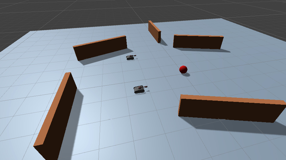
Figure 8.1 – An image of the NavMesh01-Simple scene, a plane with obstacles
In the following subsections, we will set up the walls as obstacles, bake the NavMesh, and configure the tanks.
Navigation static
Once we add the floor and the obstacles, it is essential to mark them with the Navigation Static tag so that the NavMesh generator knows that they need to be taken into account during the baking process. To do this, select all of the objects, click on the Static button, and choose Navigation Static, as shown in the following screenshot:
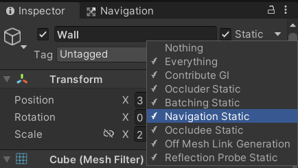
Figure 8.2 – The Navigation Static property
Baking the NavMesh
Now that we have completed the scene, let's bake the NavMesh. To do that, follow these steps:
- Navigate to Window | AI | Navigation, and you should be able to see this window:
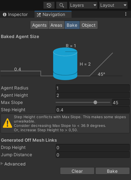
Figure 8.3 – Navigation window
Info
All the properties in the Navigation window are pretty self-explanatory: Agent Radius and Agent Height represent the size of the virtual agent used by Unity to bake the NavMesh, Max Slope is the value in degrees of the sharpest incline the character can walk up, and so on. If we have multiple AI agents, we should bake the NavMesh using the radius and height of the smallest AI character. For more information, you can check out the following Unity reference documentation: https://docs.unity3d.com/Manual/Navigation.html.
- Select the plane and, in the Object tab, set its area to Walkable.
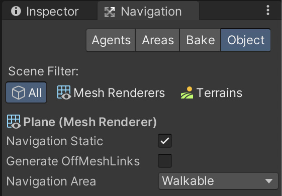
Figure 8.4 – The Object section of the Navigation panel
- Leave everything else with the default values and click on Bake.
- You should see a progress bar baking the NavMesh for your scene, and after a while, you should see the NavMesh in your scene, as shown in the following screenshot:
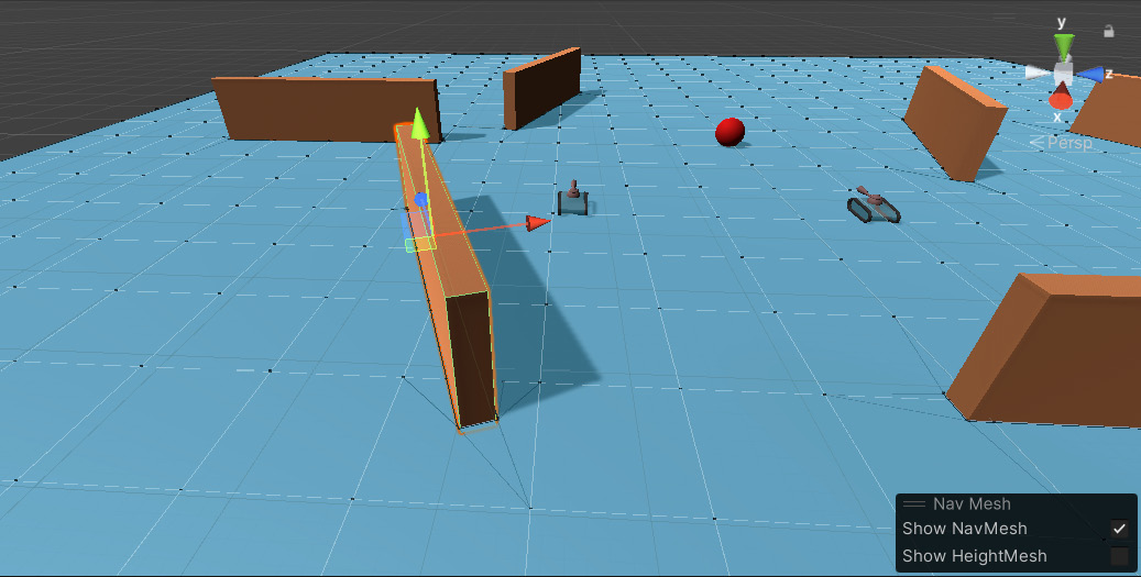
Figure 8.5 – The baking of a NavMesh
NavMesh agent
At this point, we have completed the super-simple scene setup. Now, let's add some AI agents to see if it works:
- As a character, we use our trustworthy tank model. However, do not worry if you're working in a different scene and have a different model. Everything works the same way independently of the model.
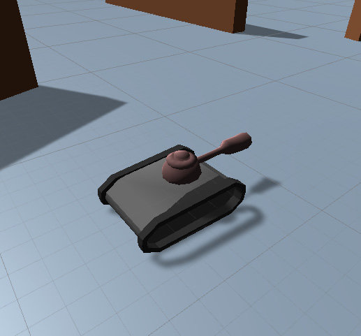
Figure 8.6 – Tank entity
- Add the Nav Mesh Agent component to our tank entity. This component makes pathfinding easy. We do not need to implement pathfinding algorithms such as A* anymore. Instead, we only need to set the destination property of the component at runtime, and the component will compute the path using Unity's internal pathfinding algorithm.
- Navigate to Component | Navigation | Nav Mesh Agent to add this component:
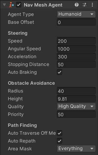
Figure 8.7 – Nav Mesh Agent properties
Info
You can find the official Unity reference for the Nav Mesh Agent at https://docs.unity3d.com/Manual/class-NavMeshAgent.html.
One property to note is the Area Mask property. It specifies the NavMesh layers that this NavMesh agent can walk on. We will talk about navigation layers in the Baking navigation areas section.
Updating an agent's destinations
Now that we have set up our AI agent, we need a way to tell it where to go and update the destination of the tank to the mouse click position.
So, let's add a sphere entity, which we use as a marker object, and then attach the Target.cs script to an empty game object. Then, drag and drop this sphere entity onto this script's targetMarker transform property in the Inspector.
The Target.cs class
This script contains a simple class that does three things:
- Gets the mouse click position using a ray
- Updates the marker position
- Updates the destination property of all the NavMesh agents
The following lines show the Target class's code:
using UnityEngine;
using System.Collections;
public class Target : MonoBehaviour {
private UnityEngine.AI.NavMeshAgent[] navAgents;
public Transform targetMarker;
public float verticalOffset = 10.0f;
void Start() {
navAgents = FindObjectsOfType(
typeof(UnityEngine.AI.NavMeshAgent)) as
UnityEngine.AI.NavMeshAgent[];
}
void UpdateTargets(Vector3 targetPosition) {
foreach (UnityEngine.AI.NavMeshAgent agent in
navAgents) {
agent.destination = targetPosition;
}
}
void Update() {
// Get the point of the hit position when the mouse
// is being clicked
if(Input.GetMouseButtonDown(0)) {
Ray ray = Camera.main.ScreenPointToRay(
Input.mousePosition);
if (Physics.Raycast(ray.origin, ray.direction,
out var hitInfo)) {
Vector3 targetPosition = hitInfo.point;
UpdateTargets(targetPosition);
targetMarker.position = targetPosition +
new Vector3(0, verticalOffset, 0);
}
}
}
}
At the start of the game, we look for all the NavMeshAgent type entities in our game and store them in our referenced NavMeshAgent array (note that if you want to spawn new agents at runtime, you need to update the navAgents list). Then, whenever there's a mouse click event, we do a simple raycast to determine the first object colliding with the ray. If the beam hits an object, we update the position of our marker and update each NavMesh agent's destination by setting the destination property with the new position. We will be using this script throughout this chapter to tell the destination position for our AI agents.
Now, test the scene, and click on a point that you want your tanks to go to. The tanks should move as close as possible to that point while avoiding every static obstacle (in this case, the walls).
Setting up a scene with slopes
Let's build a scene with some slopes, like this:
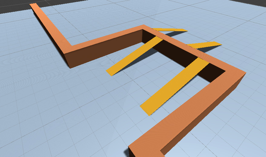
Figure 8.8 – Scene with slopes-NavMesh02-Slope.scene
One important thing to note is that the slopes and the wall should be in contact. If we want to use NavMeshes, objects need to be perfectly connected. Otherwise, there'll be gaps in the NavMesh, and the Agents will not be able to find the path anymore. There's a feature called Off Mesh Link generation to solve similar problems, but we will look at Off Mesh Links in the Using Off Mesh Links section later in this chapter. For now, let's concentrate on building the slope:
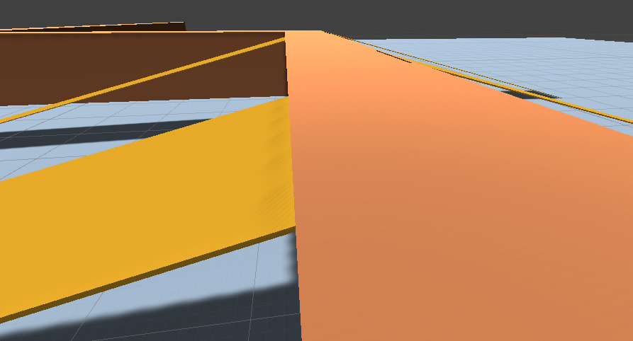
Figure 8.9 – A well-connected slope
- We can adjust the Max Slope property in the Navigation window's Bake tab according to the level of slope in our scenes that we want to allow the Agents to travel. We'll use 45 degrees here. If your slopes are steeper than this, you can use a higher Max Slope value.
- Bake the scene, and you should have generated a NavMesh, like this:
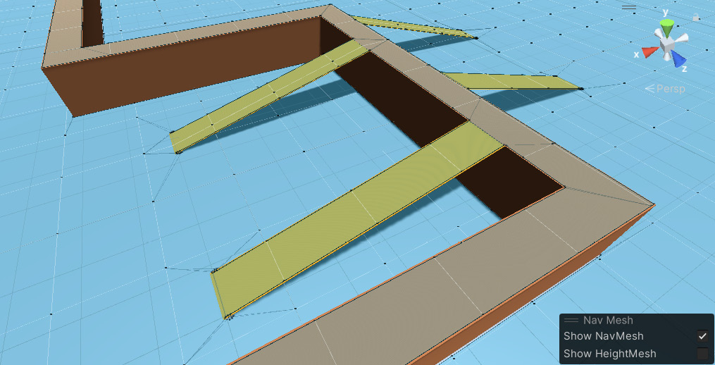
Figure 8.10 – The generated NavMesh
- We will place some tanks with the Nav Mesh Agent component.
- Create a new cube object and use it as the target reference position.
- We will be using our previous Target.cs script to update the destination property of the AI agent.
- Test run the scene, and you should see the AI agent crossing the slopes to reach the target.
Congratulation, you have implemented your first basic NavMesh-powered AI. Now, you can implement agents able to navigate over simple plains. What if we want more complex scenarios? That's the topic of the next section.
Baking navigation areas with different costs
In games with complex environments, we usually have areas that are harder to traverse than others. For example, crossing a lake with a bridge is less challenging than crossing it without a bridge. To simulate this, we want to make crossing the lake more costly than using a bridge. This section will look at navigation areas that define different layers with different navigation cost values.
For this, we build a scene, as shown in Figure 8.11. Three planes represent two ground planes separated by a water plane and connected by a bridge-like structure. As you can see, crossing over the water plane is the most direct way to traverse the lake; however, passing through the water costs more than using the bridge and, therefore, the pathfinding algorithm will prefer the bridge to the water:
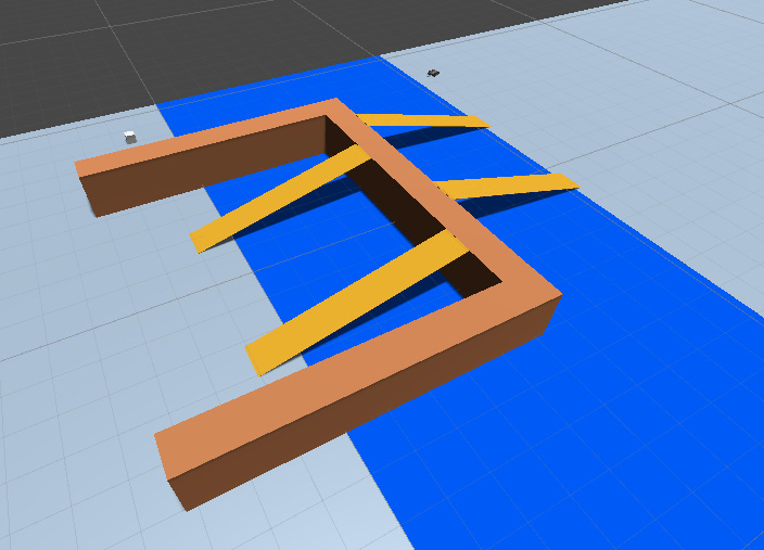
Figure 8.11 – Scene with layers – NavMesh03-Layers.scene
Let's follow a step-by-step procedure so that we can create a navigation area:
- Go to the Navigation window and select the Areas section:
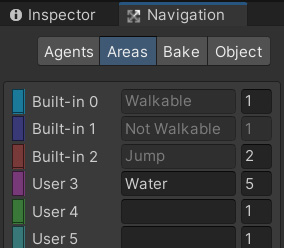
Figure 8.12 – The Areas section in the Navigation window
Unity comes with three default layers: Default, Not Walkable, and Jump, each with potentially different cost values.
- Let's add a new layer called Water and give it a cost of 5.
- Select the water plane.
- Go to the Navigation window and, in the Object tab, set Navigation Area to Water:
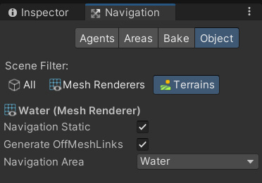
Figure 8.13 – Water layer
- Bake the NavMesh for the scene and run it to test it.
You should see that the AI agents now choose the slope rather than going through the plane marked as the water layer because it's more expensive to traverse the water. Try experimenting with placing the target object at different points on the water plane. You should see that the AI agents sometimes swim back to the shore and sometimes take the bridge rather than trying to swim across the water.
Info
You can find the official Unity documentation for NavMesh Areas at https://docs.unity3d.com/Manual/nav-AreasAndCosts.html.
Using Off Mesh Links to connect gaps between areas
Sometimes, there may be some gaps in the scene that can make the NavMeshes disconnected. For instance, the Agents do not find a path in our previous examples if we do not tightly connect the slopes to the walls, so we need to make it possible to jump over such gaps. In another example, we may want to set up points where our agents can jump off the wall onto the plane below. Unity has a feature called Off Mesh Links to connect such gaps. Off Mesh Links can be set up manually or can be automatically generated by Unity's NavMesh generator.
Here's the scene that we're going to build in this example. As you can see in Figure 8.14, there's a small gap between the two planes.
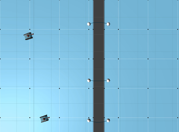
Figure 8.14 – The scene with Off Mesh Links – NavMesh04-OffMeshLinks.scene
In this section, we will learn how to connect these two planes using Off Mesh Links.
Generated Off Mesh Links
Firstly, we use autogenerated Off Mesh Links to connect the two planes. To do that, we need to follow these steps:
- Mark these two planes as Off Mesh Link Generation and Static in the property Inspector, as shown in the following screenshot:
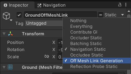
Figure 8.15 – Off Mesh Link Generation and Static
- Go to the Navigation window and look at the properties on the Bake tab. You can set the distance threshold to autogenerate Off Mesh Links:
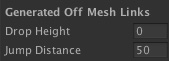
Figure 8.16 – Generated Off Mesh Links properties
- Click on Bake, and you should have Off Mesh Links connecting the two planes, like this:
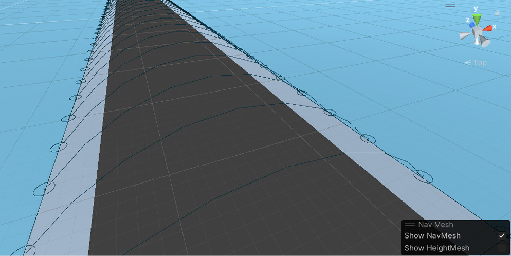
Figure 8.17 – Generated Off Mesh Links
- Now, our AI agents can find the path between the planes. But first, ensure that the tanks have Jump enabled in the Area Mask property of the Nav Mesh Agent component, as shown in Figure 8.18:
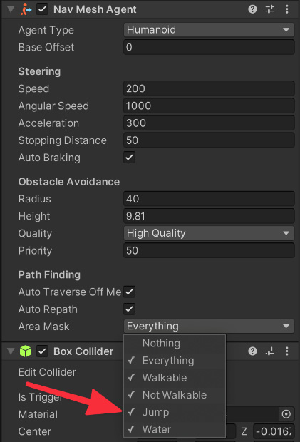
Figure 8.18 – The Area Mask configuration for the Tanks
If everything is correct, agents will essentially jump to the other plane once they reach the edge of the plane and find an Off Mesh Link component. But, of course, if jumping agents are not what we want (after all, who has ever seen a jumping tank?), we should instead put a bridge for the Agents to cross.
Manual Off Mesh Links
If we don't want to generate Off Mesh Links along the edge and, instead, we want the Agents to reach a certain point before teleporting to the other side, then we need to set up the Off Mesh Links manually, as we can see in Figure 8.19:
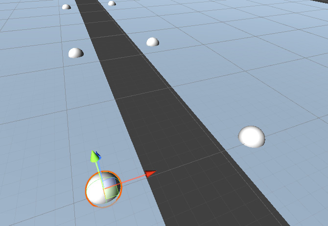
Figure 8.19 – Manual Off Mesh Links setup
Execute the following steps to set up the Off Mesh Links manually:
- We initialize a scene with a significant gap between the two planes. Then, we place two pairs of sphere entities on each side of the plane.
- Choose a sphere and add an Off Mesh Link component by navigating to Component | Navigation | Off Mesh Link. We only need to add this component to one sphere.
- Next, drag and drop the first sphere to the Start property and the other sphere to the End property:
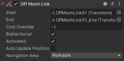
Figure 8.20 – Off Mesh Link component
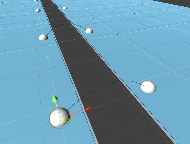
Figure 8.21 – Manually generated Off Mesh Links
- The manual Off Mesh Links now connect the two planes, and AI agents can use them to traverse terrain, even in the presence of gaps.
Info
You can find Unity's official reference for Off Mesh Links at https://docs.unity3d.com/Manual/nav-CreateOffMeshLink.html.
This last demo concludes our exploration of Unity's NavMeshes. You should now know all the basics of this vital tool for AI character development.
Summary
In this chapter, we learned how to generate and use NavMeshes to implement pathfinding for our games. First, we studied how to set up different navigation layers with varying costs for pathfinding. Then, using the destination property, we used the Nav Mesh Agent component to find the path and move toward the target. Next, we set up Off Mesh Links to connect the gaps between the NavMeshes using the autogeneration feature and a manual setup with the Off Mesh Link component.
With all this information, we can now easily create simple games with a reasonably complicated AI. For example, you can try to set the destination property of AI tanks to the player's tank's position and make them follow it. Then, using simple FSMs, they can start attacking the player once they reach a certain distance. FSMs have taken us far, but they have their limits. In the next chapter, we will learn about Behavior Trees and how we can use them to make AI decisions in even the most complex games.