
12
System Design and Architecture Landscape
In this chapter, we’ll cover two of the most important technical skills that a TPM possesses: system design and architectural landscape design. These are the levers we use to influence the technical direction of our organizations.
We start out in our career focusing on system designs in individual projects and influencing the right design for the requirements and services. As we grow, we start looking at the architectural landscape around our projects and programs to see patterns of opportunity and areas of risk. We start to influence the teams around us and the organization as a whole.
We’ll explore system designs and the architectural landscape through the following:
- Learning about common system design patterns
- Seeing the forest and the trees
- Examining an architecture landscape
Let’s dive in!
Learning about common system design patterns
As a TPM, you split your time between the high-level scope, which spans across multiple systems, and the weeds of a specific feature design. It’s due to this breadth and depth that system design is one of the most important technical skills a TPM can have. It’s important enough that it shows up in most interviews for the bigger tech companies. I’ll cover the aspects of system design that you need to consider to ensure that your design is well thought out.
When we think about system design, we often conjure up a diagram of multiple services, each covering a single function or area of concern. However, system designs come in many different sizes and complexities. On a smaller scale, a feature design, such as a feature to add a new contact to your contact list in the Mercury messenger app, is its own system design. Somewhere in between these is a system design for an entire desktop or mobile application.
As a TPM, you need to be prepared to work with a design at any of these levels of complexity. Many designs will comprise more than one design pattern, especially for complex systems. The names and behaviors of these patterns may be used in the designs themselves and therefore need to be understood. Knowing the behaviors and key features of design patterns will also make evaluating them more effective. As such, I’ll walk through some of the more predominant system design patterns (often referred to as architectural patterns) that are in use today.
Model-View-Presenter
The Model-View-Presenter (MVP) design pattern is a variant of the Model-View-Controller (MVC) pattern. Where MVC is popular in client-server applications, MVP is used often in desktop applications:
- The model is the data model of the application. All the data manipulation and storage happens in this layer.
- The view is the user interface at the top of the diagram. This displays all of the data in the application in ways that make sense to the user.
- The presenter sits in between the model and view and acts as the connecting layer between them. The user interacts with the presenter, usually through input fields in the view such as text boxes and buttons, which triggers events. The events live in the presenter and make changes in the model based on the event that occurred.
Let’s try to understand this better with the help of an example:
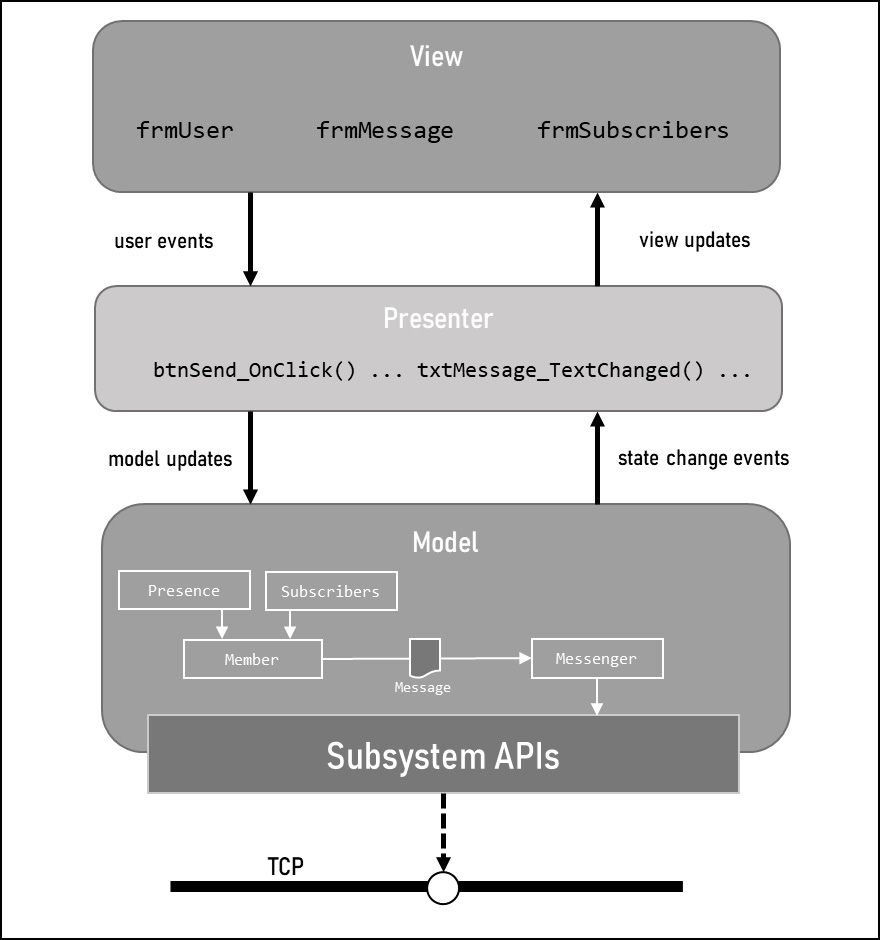
Figure 12.1 – Windows Mercury application system design
In this example, the model is broken down into three sub-components, the first of which are the business objects. These are the classes that house the data for the user (the member), their messages, their contacts, and their subscribers. The second is the messenger class that handles sending and receiving of messages across the network. Lastly is the subsystem that is shared across the operating systems that talks to the TCP network layer (via system APIs) to transport the messages.
The view displays the data model based on the context of the user actions from the presenter. For instance, the PresenceInformation class may be displayed as a colored dot beside the username of the client logged in, where the color represents a specific status. The user may also click a drop-down button to update their status, which would be relayed back to the model as an update to the PresenceInformation class via an event in the presenter on the IndexChanged() event for the dropdown.
Object-oriented architecture
Object-Oriented Architecture (OOA) is where you use objects to model real-world concepts. Though this seems straightforward due to Object-Oriented Programming (OOP) being widespread, it does not dictate what the objects themselves are and, in many cases, the objects created are bespoke to the problem space that the application is in. However, in many industries where the software is a byproduct of or in support of the main business, the software tends to emulate real-world functions that are digitized. Actions such as filling out forms give rise to form-based applications centered around this architectural concept.
Figure 12.2 shows how OOA applies to a form-based application.
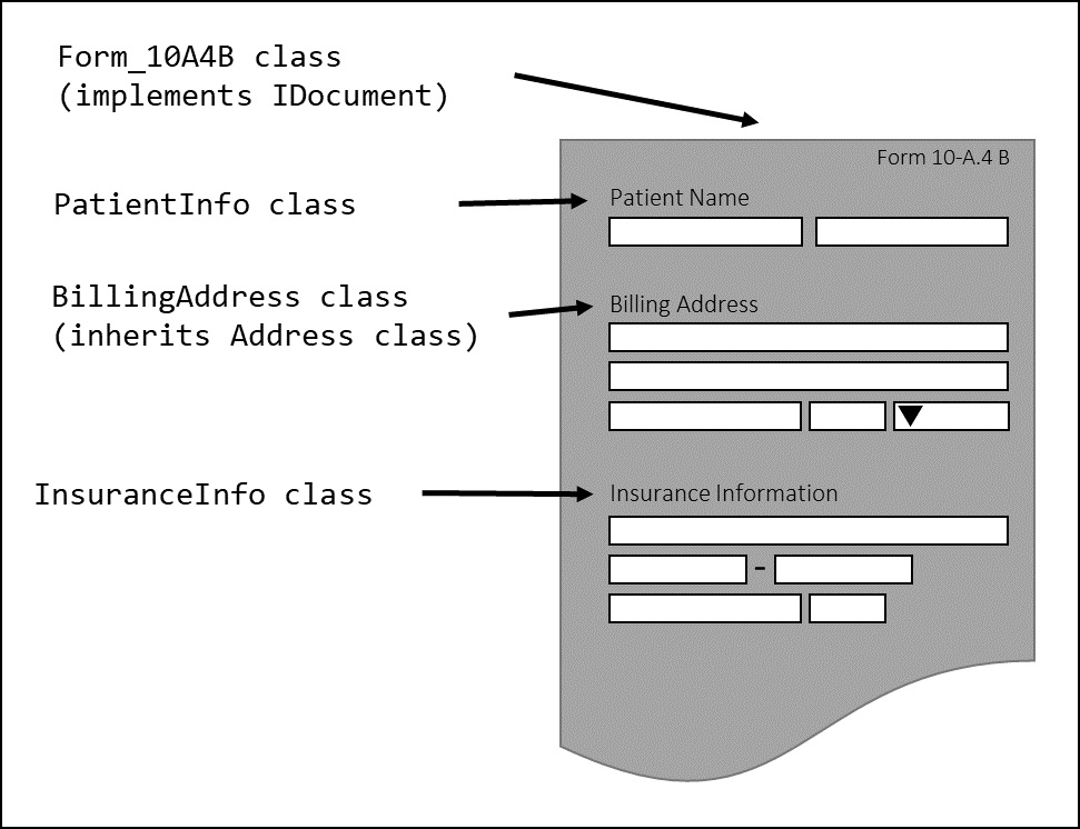
Figure 12.2 – Object-oriented architecture
The preceding figure shows a fictional US healthcare form on the right-hand side with typical information, such as the patient’s name and billing address, as well as their insurance information. Each of these bits of information is represented by a class, and these are all combined into an object that represents the form. Grouping objects together and inheriting through abstract classes, such as a generic Address class, highlights abstraction and inheritance, tenets of OOP that OOA takes advantage of.
Domain-driven design architecture
Domain-Driven Design (DDD) is a concept where domain experts work alongside the development team to influence the data model and data flow of an application. This is used in domain-heavy scenarios such as healthcare and financial systems where specific procedures, nomenclature, and protocols need to be followed.
On the surface, this feels very similar to OOA since OOA models real-world objects. However, you can model real-world objects in some cases and then not in others. In the case of DDD, the entire design is based directly on the domain, and, in some instances, the user interface is a direct reflection of the underlying model. This type of stricter coherence is not the goal of OOA.
DDD does not require the use of an OOP language, but there are natural similarities. However, there are cases where a Domain-Specific Language (DSL) such as SQL, which isn’t an OOP language, is used in conjunction with DDD for relational databases.
Event-driven architecture
Event-Driven Architecture (EDA) is where the application’s data model is updated through user-triggered and system events, which often signal to change something about the data model state. As we saw in the Model-View-Presenter section, the presenter utilizes events that are triggered by actions taken by the user on the user interface (for example, clicking a button). As such, EDA is often associated with OOA and can also be used in conjunction with DDD.
P2P architecture
This book covered P2P in Chapter 3 to some degree, but it is worth expanding upon here. There are two types of P2P networks, structured and unstructured.
A structured network has a strict topology that is adhered to as hosts leave and join the network. Every host has a list of nearby hosts, or neighbors, so that any one host can easily access another host. This type of network results in a lot of discovery traffic being broadcasted but allows you to find a peer or file quickly.
An unstructured network has no imposed structure and is resilient to changes in hosts dropping and adding to the network. However, finding a specific host or file is not guaranteed. This is a problem particularly when using P2P for file sharing, as rare files will be just as rare to successfully find. For a messaging app, the biggest hurdle to this type of structure would be finding your contacts on the network, if relying strictly on searching. A way to share direct-connect information between two parties would alleviate some of this pain.
Service-oriented architecture
Service-Oriented Architecture (SOA) is arguably the most-used architecture in the tech industry today. SOA is the basis for cloud-based architectures and offers a logical separation of concerns in larger organizations.
Figure 12.3 takes the Mercury desktop application from Figure 12.1 and re-imagines it in an SOA setting. Let’s take a look at how this changes the design and behavior of the system.
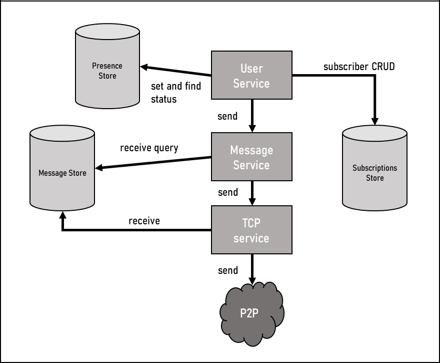
Figure 12.3 – Mercury re-imagined as an SOA
In the preceding figure, the three sections of the model from the MVP are now distinct services. User Service is essentially the user model objects and controls all aspects of the user. Now that what was a single desktop application is represented by multiple services and is decentralized, we need storage mechanisms to house what might have been in memory or serialized to the local disk in a desktop application. User Service connects to Presence Store as well as Subscriptions Store. User Service connects to Message Service, which is an analog for the Message class in Figure 12.1. It connects to TCP Service, which handles both sending and receiving messages. This is the most important difference between the desktop system design and the SOA design. Since this is a distributed system, a user isn’t logged into a specific physical device and thus their location on the P2P network isn’t static, so a user cannot reliably be reached to receive inbound messages. TCP Service circumvents this issue by storing incoming messages in a data store that a user can query for unretrieved incoming messages.
Although not a practical example given the requirements of the P2P messaging service, this does serve as a good illustration of where certain aspects of a design might change. The lack of a centralized system often leads to a high reliance on centralized or synced data stores to handle stateful data. On the other hand, having individual services allows for scaling to be handled on the pieces of the system that need it and not others. It also serves as a concrete mechanism to ensure the separation of concerns by forcing data contracts between any two services that interact with one another.
Client-server architecture
A client-server architecture is a classic design used to connect a user to a centralized service. This is the architecture used to browse the internet and to connect to a specific website. It is also used in mobile architectures where the mobile application (the client) connects to the application’s backend on a centralized server to send and receive data.
Throughout the book, I’ve been referencing a program that builds a P2P-backed messaging system across multiple operating systems. A P2P system is relatively straightforward, so I’m going to expand the program requirements for the sake of a more representative system design. For this exercise, I’m going to add the requirement of a web-based interface for the messaging application. It will still be P2P-backed and the operating system-specific applications are still present, but this design will focus on the web interface.
Figure 12.4 showcases the system design of the web portal interfacing with the P2P network.
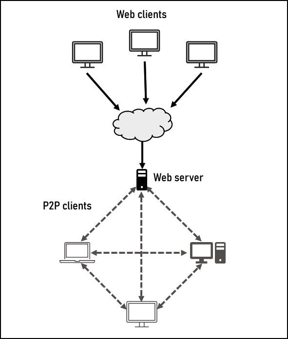
Figure 12.4 – Web browser Mercury system design
This system design is a hybrid between a traditional client-server pattern and a P2P pattern, with the biggest difference between this design and the one used in Chapter 3 being the addition of Web server. This server is the gateway for the web-based interface. Once a user connects to the web portal, the backend behaves in the same manner as a single host on the network would because the server is just another host in the network. The difference is that this particular host – or fleet of hosts – maps to multiple users instead of a single user on a single host.
This design isn’t perfect, as it is a first pass at integrating the two patterns. This is a good time to talk about some design considerations that can help when working with any design and then we’ll take a second look at this example.
Design considerations
These design considerations will help ensure your designs convey a clear intention, which will reduce project churn and has the added bonus of helping you during an interview for system design. Pay close attention to these concepts:
- Avoid vague design traits: You want your system design to be clear, so make sure you are not generalizing aspects of the design so much that you lose your key understanding of the interactions between components. Ensure that pointers between components are directional when direction matters. For instance, a network topology doesn’t need to specify directional flow, as data flows in both directions on a network. However, when a component is accessing a read-only datastore, the direction makes a difference and conveys the read-only nature through the data flow.
- Don’t omit key functionality: Missing out on functionality is usually due to an expectation of familiarity where the missing piece is seen as obvious – or parts of the design are overly generalized, which blurs the functionality between two or more parts of the system.
Latency
As is the case in most companies in the tech industry, latency, or the amount of time for which a request and response are processed, is of the utmost concern when creating a system design. Long responses, or even perceived long responses, can turn users away from using a system. This could mean lost sales revenue through not placing orders, missed ad revenue, or a reduction in market share by driving users to the competition. For these reasons, you must ensure that your system design takes latency into account when it’s applicable.
There are a few ways to combat latency that you can consider depending on how they fit with the needs of your system. If you have a lot of microservices, you can minimize network hops by co-locating services onto a single server. If you have a data store, ensure that the right data store is chosen based on the needs of the system. A system that focuses more on reads than writes, for instance, should have a data store that is optimized for reads that will reduce the overall latency of the system. The system design can show the specific database being used to highlight the high read or high write capabilities.
Though not easy to show on a system design, you can hide latency by increasing the amount of asynchronous data processing to reduce the overall time for the call to process. This is akin to swarming a project with multiple resources to bring the calendar time down.
Design patterns have a varying impact on the latency of the system, so the latency requirements both now and projected in the long term should be evaluated when selecting the right patterns to use. This does not mean you shouldn’t use a pattern just because it introduces latency, but that measures may need to be put in place to counter the latency introduced. These long-term considerations of the requirements and needs of the system are key contributions from a TPM during the design process.
Availability
Availability, or the ability of a system to respond to high volumes of requests without experiencing an outage due to no resources, is a key performance indicator that is tracked in every client-service architecture. As this architecture pattern is utilized to make thousands or millions of connections to a system, ensuring that the system can handle that load and not fail is critical to the success of the system. To mitigate availability outages, you need to increase the number of hosts that are ready to take requests. In order to ensure that the web client doesn’t need to know how many hosts you have and where they are, you can utilize a load balancer service that takes all requests to the web client and distributes the requests across the fleet of servers. Most load balancers can detect server outages and switch off traffic automatically to a misbehaving host to reduce the number of bad responses as well. In some cases, a fleet of load balancers may also be needed. Equally, when increasing hosts, other factors such as concurrent database connections need to be adjusted as well and may factor into which type of database you use for your system.
Scalability
Scalability, or the ability to quickly respond to a fluctuating call volume, is often discussed at the same time as availability, as they have similar solutions. Once the servers are behind a load balancer, servers can be added or removed without compromising client connections. In many systems, the ability to add and remove on-demand is key to scalability, as it can save on costs to reduce the fleet size in off-peak times and only have a large fleet when it is needed.
Now that we’ve discussed some common concerns with client-server architecture, let’s take a look at the architecture diagram again.
Defendable choices
Above all of these individual design considerations and patterns, you’ll want to ensure that the design you have created is defendable. There is more than one way to solve a problem and a system design is no exception to that rule. As such, you need to understand the choices you have made in the design and why you made them. I’ve found that in most interviews, so long as you understand the trade-offs you are making, the outcome is often favorable. You can always be taught new ways of solving problems, so the goal here is more to demonstrate that you can think critically and adjust as new data comes in that may impact your design considerations.
If you are already a TPM, then you will often review designs from your development team and can use these concepts to ensure that the design holds up to scrutiny. Aside from these high-level checks, you will also look at the designs and see how they hold up to the other projects and programs that are in flight and are there to ensure that other teams, services, and projects are considered in the design.
Now that we’ve discussed some design considerations, let’s take a second look at the client-server architecture from Figure 12.4 with some of these considerations applied to Figure 12.5 here.
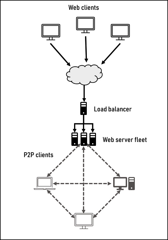
Figure 12.5 – System design with availability and scalability mitigations
As you can see, the network diagram now has a fleet of boxes for the web service, all backed by the added Load balancer to distribute the requests. As the Mercury application is a single local application, there are no latency concerns that need to be addressed at the system design level, although this will be revisited at the architectural landscape level. The availability and scalability have been addressed through the addition of a load balancer, which supports multiple web servers to ensure enough connections are available during peak demand. As with Figure 12.3, this design has a similar concern where a web client doesn’t have a persistent connection to the P2P network, so inbound requests won’t know which server to send the connection to. A similar database solution that stores incoming messages that the web client can query would be one solution to this.
Now that we’ve talked about all of the system design patterns and how to make a good and defensible design, let’s expand our scope and learn to see the forest and the trees.
Seeing the forest and the trees
The architectural landscape is not often talked about as a standalone topic outside of specific instances such as migrating from on-premises to the cloud. In many ways, it’s similar to system design in its intention, as well as patterns. In most cases, the design of a single system within a larger ecosystem will match the design patterns of the systems around it. If the trend at your company is to utilize SOA, then you will see SOA at every level. The biggest difference between the architectural landscape and system design is the scope that the design encompasses.
You can’t see the forest for the trees is a proverb that was first published in 1546 in The Proverbs of John Heywood. The idea is that from the middle of a dense forest, you can see every tree that surrounds you in great detail from the trunk all the way to the crown of the tree – but from this vantage point, you literally cannot see the whole forest; you don’t know how vast it is or the directions in which it flows, as the breadth and depth are lost. This saying has become so common it is now an idiom in the English language.
People often relate to this idiom when they are too close to a problem to see the bigger picture or have been too close for too long to see clearly. Think back to a time when a problem was frustrating you and you worked to solve it with no progress. Then, you stepped away from the problem and when you came back, the solution came to you quickly! It came because you changed your perspective by allowing different information to come into play. Simply put, you saw the forest.
Pro tip
I offer a slightly different version of this proverb as a directive to all TPMs: You must see the forest as well as the trees.
A TPM must have both a breadth and depth of knowledge. The depth (or the trees) refers to system designs and the breadth refers to the architectural landscape (or the forest). You can extend this analogy further and see where a system design and an architecture landscape are one and the same; when no other systems surround the one that the system design describes, then it is both the system design and the architectural landscape, like a lone tree on a hill. However, you can then zoom out from that tree far enough to see other trees and understand where it fits into the larger picture of the trees around it. That is to say, no modern system is in isolation, but the level at which you focus will depend on the needs of your role. It may be at the team level, organization or department level, or company level.
Important tools we use to see the bigger picture better (the forest) are program, product, and team roadmaps. These roadmaps encompass different components of an architectural landscape. Each one looks into the future deliverables of a group of systems. More importantly, they describe either directly or indirectly the intention of that group of systems, why they exist, and what they are striving to become. The intentions, as well as discrete deliverables, are what determine the picture of the architectural landscape both as it exists today and how it will change in the future. Some companies publish technology directives that give the general direction that the company’s platforms are evolving toward, which can include the technologies that will be centralized.
A TPM will be expected to pick up on these cues from roadmaps and directives and point out when there’s an issue or an opportunity between multiple projects or programs. A Principal TPM is expected to see these issues or opportunities without being prompted whereas a Senior TPM is expected to see these connections as they relate to the projects or programs they run.
On the other hand, we also need to recognize the individual trees. Your contribution to design reviews at the system level will lean on your knowledge of the architectural landscape as you set outside context against the proposed system design. In general, an SDE’s focus is on the system design and its interactions within the context of their own software. Just like a TPM, the SDE’s breadth also grows as they ascend the corporate ladder. Even so, the TPM’s job of looking across projects and cross-organization is always required.
Figure 12.6 illustrates the varying areas of concern of a TPM, SDM, and SDE across an architectural landscape.

Figure 12.6 – Areas of concern across job families
In the preceding figure, each column of boxes represents the services owned by a single SDM. These services are the purview of our SDM, and they are expected to understand each one in its entirety, as well as how they interact with each other. It’s often necessary for our SDM to know about the services outside of their team that have a relationship with one or more of their own services. In these instances, the SDM area of concern will look similar to the Senior SDE area of concern.
The circles represent the three main areas of concern for our SDE. The smallest inner circle is an entry-level SDE who is mainly concerned with a single service. An industry SDE will need to stretch to related services, often under the same SDM that they report to. They know how these services work and how they interact with one another and are starting to learn about outside dependencies. The largest circle is the Senior SDE who needs to know about all services under their SDM, as well as the services that have a relationship with them from other teams.
The last group is our TPM, represented by the rounded squares in the figure. An entry-level TPM starts out with the same expectations as an industry SDE in that they need to know the complete architecture of their SDM (also known as an embedded TPM) or the services they are focused on. An industry TPM is expected to know about the dependent systems of their focus area as the initiatives going on in that space. Lastly, a Senior TPM is expected to understand the architecture of their organization – not necessarily to the same level of detail as with the services they focus on, but at least the high-level data flow and interactions.
This illustration is a common example of the areas of concern and how they overlap but is by no means the only breakdown. Highly specialized TPMs may focus more on the depth of their services or on certain aspects such as security. In some organizations, the Senior SDE’s purview may be the same as a Senior TPM, especially for a seasoned SDE on the path to Principal. In cases where a TPM isn’t present, an SDM’s area of concern and influence may also need to expand to fill in the gap.
We’ve focused on seeing the trees through various system designs and how this aligns with your day-to-day role as a TPM. We also see how the areas of concern grow as your level grows. Next, we’ll take a look at the forest by learning what an architectural landscape is and how it is different from a system design.
Examining an architecture landscape
To get a good understanding of what an architecture landscape is, we’ll compare a system design with an architecture landscape. We’ll follow this up with a look into the implementation of the Mercury messaging application on a corporate network.
There is more in common between a system design and an architectural landscape than not. The design patterns between the two are the same and are often referred to as architectural patterns. They also both describe the relationship between components of an ecosystem that share some relationship either in the data they process and handle or the function that they collectively perform.
Where they can differ is the scope and depth of the design. A system design is limited in scope, as it often covers a single feature or limited data flow between highly related systems. The design may dive into API definitions, as well as illustrate the data model and how it flows through the system.
An architectural diagram usually covers higher-level system interactions and multiple systems and features that share a common theme. APIs and data field flows are less relevant at the level of the architectural landscape.
To start, in Figure 12.7, we compare a system design to an architectural landscape.
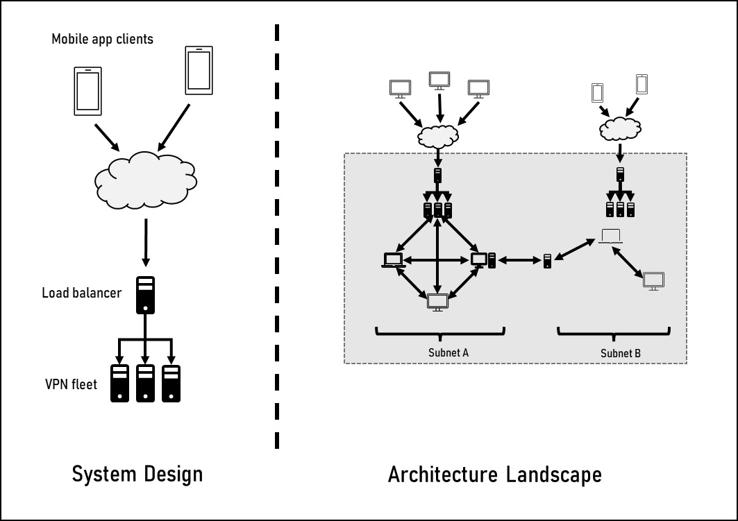
Figure 12.7 – System design versus architectural landscape
In the preceding figure, the left-hand side is the system design of a Virtual Private Network (VPN). A VPN provides a secure connection to a specific network as though your device were on that network and is often used in corporate settings to give employees access to the corporate network while working remotely. This design describes a single feature of gaining access to a network through a load-balanced VPN.
On the right-hand side is the architecture diagram for the Mercury application implemented in a corporate network. On the upper right-hand side of this picture, you can see the VPN system design within the architectural landscape. The landscape tells the story of the entire Mercury system, including all points of entry and network traversals. It does not detail the Mercury application as we saw in Figure 12.1, but it does include multiple independent system designs, including the web-based client system design from Figure 12.5.
Next, let’s take a closer look at the architectural landscape including labels, and discuss the various components. Figure 12.8 shows the Mercury corporate installation in greater detail.
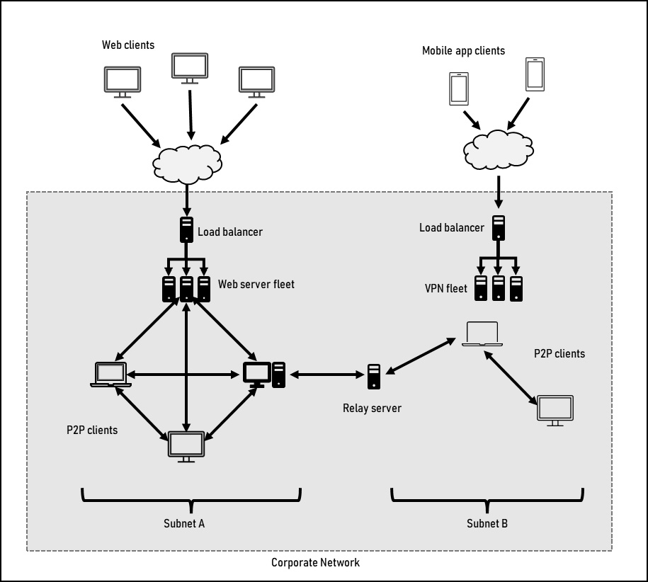
Figure 12.8 – Mercury corporate installation architectural landscape
We’ve seen various parts of this architectural landscape throughout the book, starting with the P2P network on the right-hand side. This is representative of an unstructured P2P network and is contained within the same network as well as on the same subnet – in this case, denoted as Subnet A. The web client that we added in this chapter to illustrate a client-server architecture is above the P2P network and connected to the network as Web server fleet where each member of the fleet is on the network.
New to this architecture landscape is the second subnet, Relay server, and VPN fleet. A large corporate network may need to be segregated into multiple sub-networks (subnets) to reduce network collisions by having fewer devices share the same physical wire for data transmission. In a traditional network, routers are used to transmit data across subnets. In a P2P network, all hosts have direct connections to other hosts, which does not include routers. To get around this limitation, the relay server that is part of the P2P network would need to receive a P2P packet and then relay it to the correct subnet to which it is also connected. Lastly, to get the Mercury application on mobile devices onto the corporate network, the design incorporates a VPN. Through the Mercury application on the device, it first establishes a connection to the P2P network via the VPN. In this sense, it behaves a lot like the web client in how it connects to and interacts with the P2P network.
To be clear, many of these additions to the architecture go against the original requirements of the Mercury program, specifically around not requiring any centralized setup or maintenance. On a hyper-local, single subnet network, none of these components are necessary and the simple P2P design would suffice. However, these are good additions to illustrate key design concepts and the overall complexity that can come up when working through requirements.
All of these system designs come together to paint a larger picture of how the Mercury messaging system could be implemented. As a TPM, I may be on the Windows team and thus largely focused on the internal system design of the application itself as seen in Figure 12.1. I might also be the lead TPM for the Mercury program and thus need to understand the full architectural landscape in order to effectively oversee all projects in the program.
Lastly, it’s worth noting that both the architectural landscape and the system design utilized multiple design patterns to fit the needs of the ecosystem.
Summary
In this chapter, we explored the trees as well as the forest. Just as a forest is made up of trees and therefore trees and forests share a lot in common, so do system designs and architectural landscapes.
We learned about various design patterns that are used in both system designs and architectural landscapes. We discussed the elements of a good design, as well as a bad design. Above all, we discussed the importance of defensible choices, as there is always more than one way to design a system.
Finally, we dove into the differences between a system design and architectural landscape and how this relates to the areas of concern for a TPM throughout their career.
In Chapter 13, we’ll close by discussing how to use your technical background to enhance your project and program management skills.
Further reading
- Architectural Patterns, by Pethuru Raj, et al.
This book covers all of the system design patterns discussed in this chapter, as well as additional patterns. If this is an area of particular interest to you, this is a good place to start.
https://www.packtpub.com/product/architectural-patterns/9781787287495
- Solutions Architect’s Handbook – Second Edition, by Saurabh Shrivastava, et al.
The work of a solutions architect is a popular field, as it focuses on moving from on-premises to the cloud. To do this, a full understanding of the current architecture is needed in order to determine the right solution for the cloud. As such, this offers a great view of understanding an entire architecture.
https://www.packtpub.com/product/solutions-architect-s-handbook/9781801816618
- Hands-On Design Patterns with Java, by Dr. Edward Lavieri
This book gives you a real hands-on approach to learning about a large number of design patterns using Java. All the design patterns I covered are also covered here in greater depth, making it a good next step to dive deeper.
https://www.packtpub.com/product/hands-on-design-patterns-with-java/9781789809770