
Chapter 2. Architecture of Mule and ServiceMix
In chapter 1 we defined an ESB, explored its features, and showed you how an ESB can be used to solve integration problems. We also introduced two popular open source ESBs, Mule and Apache ServiceMix, and you saw a hello world example of these two ESBs in action.
In this chapter we look deeper into these two technologies. More specifically, we examine the architecture of Mule 2.0.2 and ServiceMix 3.2.1. We start by explaining Mule and show you its main concepts and how they work together.
Next, we explore ServiceMix in two distinct sections. In section 2.2 we address Java business integration (JBI), since that’s the foundational specification of ServiceMix. Then, we investigate ServiceMix in more detail in section 2.3.
At the end of this chapter you’ll have learned the architecture of both Mule and ServiceMix and how the basic components of these two ESBs are designed. You’ll also have a good knowledge of JBI and how that specification is used in ServiceMix.
Just a reminder: you can download all the source code for the examples in this book from the book’s website. In the next chapter we explain in more depth how you can set up a local environment in which you can run these examples.
2.1. Mule architecture and components
In this section we give you more in-depth information on the ideas behind Mule 2.0. This section provides a good overview of how messages flow through the Mule ESB and thus forms a good foundation for the examples in upcoming chapters.
In the following subsections we explain the main architectural concepts of Mule and show you how they all work together by diving into a complete Mule configuration file. For the moment we only focus on the most important parts of Mule and tackle the more advanced topics in the following chapters.
2.1.1. Mule components overview
Mule’s architecture consists of a number of components that work together to provide all the features an ESB should provide. Figure 2.1 shows the main parts and how they interact.
Figure 2.1. This figure illustrates the main concepts of the Mule ESB that enable it to process incoming messages to the proper target applications.
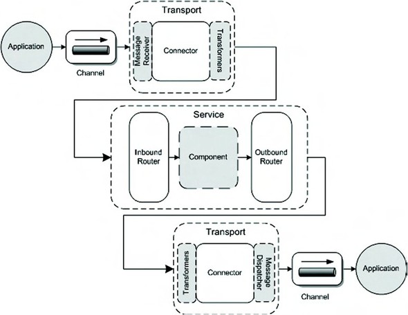
Figure 2.1 shows most of the foundational concepts of Mule. The figure is designed to illustrate the logic order of processing, from receiving an incoming message to sending the message to the right destination. Mule uses transports to receive and send messages from and to all kinds of sources, including Java Message Service (JMS), HTTP, FTP, and files. Another important concept of Mule is the service definition, which consists of an inbound router, a component, and an outbound router. The service definition is where you as a Mule developer will implement the integration logic necessary to solve your integration challenge.
In the next sections, we discuss the various concepts shown here and things will become a lot clearer. Before we delve into each component, we begin by introducing them. Table 2.1 describes the Mule components shown in figure 2.1.
Table 2.1. The main concepts of the Mule architecture
|
Name |
Description |
|---|---|
| Application | This identifies the application we’re integrating with. It can be anything—an old legacy Cobol system, a .NET application, a J2EE application, or even another Mule instance. |
| Channel | A channel (an Enterprise Integration pattern) provides a way for external applications to communicate with Mule. Channels can also be used inside Mule to wire services together. |
| Message receiver | As the name implies, this component can receive information from a certain channel. Mule provides receivers for a lot of common standards and technologies. |
| Connector | A connector understands how to send and receive data from certain channels. As you can see in the previous figure, the connector is present both at the receiving and the sending ends. The message receiver and message dispatcher are part of the connector. |
| Transformer | We’ve already seen this component in chapter 1. A transformer transforms data from one format to another. |
| Inbound router | An inbound router determines what to do with a message once it’s received from a channel. |
| Component | The component is the logical place within the Mule architecture to implement integration logic not provided by other Mule parts. A component can be implemented with a number of technologies: POJO, Groovy Script, REST service, and BPM, among others. |
| Outbound router | This is much the same as the inbound router, but this component determines where a message is sent to after it’s processed by the component. |
| Message dispatcher | This is the opposite of the message receiver. This component knows how to send information over a specific channel. |
To be able to comprehend all the concepts from table 2.1, let’s look at the example shown in figure 2.2.
Figure 2.2. This example shows the use of the main concepts of Mule. A CSV file is sent to Mule with an FTP server, and Mule transforms the message to XML and sends it on to the payment system.

In the example shown in figure 2.2, a comma-separated values (CSV) message is read from an FTP server, transformed into an XML message, and then sent to the payment service. After the payment service finishes processing the message, the message is again transformed to CSV and dropped on the file system.
If we implement this using Mule and look at the various components we need, we can list the following actions taking place:
- The application of company A puts the CSV file in a specified FTP directory.
- This directory serves as a channel into the running Mule instance.
- Mule uses a message receiver, which is part of the incoming connector, to read the file from the file channel, so that it can be processed further.
- The transformer converts the incoming message to the XML format required by the payment service.
- The inbound router checks where the message needs to be sent to. In this case the message is sent to the payment service.
- The payment service is declared as a component, implemented as a POJO that can receive messages from Mule.
- After the message has been processed by the payment service, Mule uses an outbound router to determine where the message needs to be sent to next.
- A message dispatcher, which is part of the outgoing connector, is now used to send the message to a channel. In this case this channel is once again a file directory on the FTP server, where the application from company A can pick it up again.
As you can see, the Mule architecture provides all the basic components that are needed for application integration. Before we look at the various parts in more detail, let’s quickly look at how you as a developer configure Mule. Configuring Mule is done using XML. You create a file that specifies the transformers you want to use, which routers need to be used, and so forth. Let’s look at the parts this file contains in figure 2.3 before we move on to the code examples.
Figure 2.3. An overview of the main parts of a Mule configuration file. This figure also shows that Spring beans can be easily integrated in the Mule configuration.

As you can see in figure 2.3, a lot of the already mentioned Mule concepts are configured in this file. If you want to use message filters, specific transformers, and connectors for technologies, they are all configured in this XML file. We must also define a Mule model to contain all our Mule services. A Mule service is a simple container component that specifies on which channels we’re listening (the inbound router), how the routing is handled (the outbound router), and which component is invoked.
Now that we’ve introduced you to the basic architecture and concepts of Mule, let’s look somewhat deeper into these concepts.
2.1.2. Mule endpoints
Channels provide a way for external systems to communicate with Mule and to let components interact with one another. However, an application needs to have a way to connect to a channel, and this can be done by creating an endpoint. The channels, connectors, senders, and receivers work together to accomplish this.
The configuration of an endpoint changed between Mule version 1.4 and Mule version 2.0. To understand the use of endpoints in Mule, let’s first look at the old definition of endpoints, which can still be used in Mule 2.0. In the next subsection we focus on Mule 2.0–style endpoints.
Mule endpoints, old style
Before explaining how Mule works with these endpoints, let’s look at a couple of these endpoints. The ones listed here are examples of basic endpoint definitions:
<endpoint address="pop3://user:[email protected]"/>
<endpoint address="jms://topic:myTopic"/>
<endpoint address="http://mycompany.com/mule"/>
<endpoint address="file:///tmp/data/in"/>
<endpoint address="axis:http://mycompany.com/mule/services/MyUMO"/>
As you can see from this list, Mule endpoints are easy to read and understand. They describe the technology used (for example, pop3:// for email, file:// for access to the file system) and where to read or send a message to. Let’s look a bit more closely at the POP3 endpoint of the previous list:
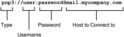
So what does the endpoint from this illustration tell us?
- We’re connecting using POP3, a protocol for accessing your email.
- Next we see the username and password that are required to connect to this endpoint.
- The final part from this endpoint is the host that we’re connecting to.
Some endpoints have additional parameters or specific naming conventions (e.g., the topic part of the JMS URL), but generally an endpoint looks like this example.
Now let’s see what can be configured on a Mule endpoint. The following shows how an endpoint in Mule is defined:
scheme://[username][:password][host][:port]/
                                 [endpoint name]/[address]?[params]
The fields from this URI are explained in table 2.2.
Table 2.2. Mule URI fields description
|
Name |
Description |
Required? |
|---|---|---|
| scheme | This is the type of connection we want to make. If we want to connect using a JMS broker, the scheme would be jms. If we need to write something to the file system, the scheme would be file. Mule already provides support for over 20 different schemes. | Yes |
| username | If a connection to a certain host requires a username, it can be provided in this part. | No |
| password | If we need to specify more than just the username, a password can also be provided by using this part. | No |
| host | Here we specify to which host we connect. If both a username and a host are used, they should be separated by a @. | Yes[*] |
| port | Here we specify to which port on the server we need to connect. If this isn’t filled in, the default port for the service is used. | No[*] |
| endpoint name | It’s possible to create reusable endpoints. These endpoints can be defined globally and used throughout the configuration file. | Yes[*] |
| address | The address specifies where we need to connect to on the previously defined host. This can, for instance, be a specific URL on an HTTP server, a specific queue name for a JMS broker, or a certain location on the file system. | Yes |
| params | Some schemes allow additional parameters that you can use to customize the behavior of this endpoint. A file endpoint, for instance, allows you to specify whether a file is deleted after it’s picked up, or that a file should be moved to a certain directory. | Yes |
*Either a host, an endpoint name, or both is required. Usually, though, you won’t use an endpoint and a host:port together. It’s possible, however. If it’s done, the host:port specified will override the host and port specified in the global endpoint.
You’ve now seen how Mule allows you to connect to various systems by using these endpoints. However, we haven’t told you everything you need to know about these endpoints. As you’ll see in later chapters, it’s also possible to define a transformer directly on an endpoint. We explain that in more detail in the following section.
A couple of more complex endpoint addresses are listed next, and with the information provided in this section you should be able to know what they do:
smtp://mule:[email protected]?subject=HelloWorld&[email protected]
file://work/incoming?pollingFrequency=10000&moveToDirectory=work/processed
jms://topic:information?username=mule&password=secret
ejb://localhost:1099/SomeService?method=remoteMethod
If you can understand what these endpoints do, you understand one of the most important concepts of the Mule architecture.
Mule endpoints, new style
Starting with Mule 2.0, the configuration of endpoints has become easier with the introduction of transport-specific namespaces and attributes. For instance, when we look at the JMS endpoint configuration from the previous section, we can also configure it with an endpoint specific to the JMS transport in Mule 2.0. It would look like this:
<jms:inbound-endpoint queue="order.queue"/>
<jms:outbound-endpoint topic="order.topic"/>
The main advantage is that you get code completion for the configuration of an endpoint related to a specific transport. This also makes it simpler to determine which properties you can use for an endpoint of a specific transport. Because this style of configuring endpoints is more powerful, we use the transport-specific namespaces in this book.
Another important difference is the use of inbound-endpoint and outbound-endpoint elements in Mule 2.0 instead of the endpoint element in Mule 1.4. This means that the inbound and outbound endpoint definitions are clearly separated and that the attributes and child elements for these endpoint definitions can be different. Let’s look at a couple of examples of more complex endpoint definitions, to be able to compare them with the Mule 1.4 complex endpoints of the previous section:
<file:inbound-endpoint path="inbox" fileAge="1000"
    pollingFrequency="2000" />
<smtp:outbound-endpoint host="localhost" port="1234"
    to="[email protected]" subject="hello" />
Now that you know how Mule interacts with incoming and outgoing messages, let’s go ahead and look at the way incoming and outgoing messages can be transformed.
2.1.3. Transformers
The next concept we discuss is the transformer. As we mentioned earlier, transformers are used to transform data from one format to another. For instance, if you decide to use a common data format for all your ESB message flows, you can use transformers to create the mappings for that format.
If you look back at figure 2.1 earlier in this chapter, you can see that transformers are applied after the message receiver has received a message. The main question here is, what does the source message look like when we receive it for transformation? If we receive one message from a JMS queue, and another one from a mail provider, you can assume the format in which we receive the messages is different.
Well, you’re partly right. Although Mule tries to hide the transport and its technical implementation as much as possible, there are some factors you need to take into account. Mule applies a sensible default transformation to an incoming and outgoing message based on the type of transport on which we receive or send the message. When we receive a message over JMS, Mule automatically transforms it based on the JMSMessage received. If a TextMessage is received, it’s transformed into a String, an ObjectMessage is transformed into an Object, and the other JMS message types also have their Java object equivalents. This is all done automatically and doesn’t require you to specify anything.
You can, of course, specify your own transformations that can override the default transformations or be applied together with them. One thing to keep in mind, though, is that when you specify your own transformers, the internal Mule transformers aren’t executed by default anymore. So if you want to also execute the default transformers, you have to configure them explicitly.
Let’s assume we want to convert a message, received from a JMS queue, from one XML format to another. To transform this message, we need the transformers specified in figure 2.4.
Figure 2.4. An example of stacked transformations, which shows how a message is transformed in two steps. First, the default JMS transformer is executed, and then an XSLT transformation converts the incoming message into a different XML format.

When the message is received, the following take place:
- The message is transformed by the default JMSToObjectTransformer, which we now have to specify explicitly because we’re also using another transformer. A JMS TextMessage goes into this transformer and a String object comes out.
- The String object is passed into the XSLT transformer, the style sheet is applied, and the message is transformed into the required XML format.
You’ve seen in the previous section that endpoints are an important part of the Mule configuration. Configuring transformers is also partly done using those endpoints. It consists of two steps. The first step is to define the transformers and assign a logical name. The XML configuration to define the transformers is shown in listing 2.1.
Listing 2.1. Transformers configuration in Mule

The JMS transformer
![]() and the XSLT transformer
and the XSLT transformer
![]() are provided by Mule, so we can easily define these transformers using the transport-specific namespace. For this example,
we don’t need any additional transformers, but to show how to configure your own developed transformer, we include the custom-transformer element
are provided by Mule, so we can easily define these transformers using the transport-specific namespace. For this example,
we don’t need any additional transformers, but to show how to configure your own developed transformer, we include the custom-transformer element
![]() . For more details about the implementation of a custom transformer, check out chapters 4 and 5.
. For more details about the implementation of a custom transformer, check out chapters 4 and 5.
The second step involves configuring these transformers on an endpoint. In this example, they’re added to an inbound endpoint:
<jms:inbound-endpoint queue="query.response">
  <transformer ref="JMSToStringTransformer"/>
  <transformer ref="XSLT"/>
</jms:inbound-endpoint>
As you can see, the transformers can be configured using the transformer element with a ref attribute, which can be set on an inbound and outbound endpoint. To configure multiple transformers, you can just use multiple transformer elements.
We’re halfway there! You’ve seen how Mule can connect to various technologies and how the messages received from and sent to those technologies can be transformed. Let’s now explore the most interesting and powerful part of Mule: the routers.
2.1.4. Routers
Looking back again at figure 2.1, you can see that there are two different types of routers: inbound and outbound. You can also see that the inbound router is applied after the transformation of a message and the outbound router is applied before the transformation. As the name implies, routers allow you to determine what to do with a message when it’s received and before it’s sent. Let’s look at an example of an inbound and an outbound router provided by Mule, so you can see how they work. In the following chapters, when we discuss routing in more depth, we also look at some of the other routers Mule provides.
Inbound router
The inbound router we’ll be looking at is called the selective consumer. With the selective consumer, we can use a filter to specify the types of messages we want to receive. For instance, we could specify that we only want to receive messages that contain a String or that match a certain XPath expression. Listing 2.2 shows a simple inbound router configuration.
Listing 2.2. Sample inbound router definition for Mule

This configuration gives a glimpse of what’s possible with Mule. In the next chapter we explain what you see in this example in greater depth. For now, this list will give you a high-level overview of what the configuration does:
- A catchall strategy
 allows you to define an endpoint to which messages are sent when they aren’t matched by any of the filters. In this case,
they’re routed to a JMS endpoint.
allows you to define an endpoint to which messages are sent when they aren’t matched by any of the filters. In this case,
they’re routed to a JMS endpoint.
- The router defined here is a SelectiveConsumer
 . The filter in this section defines whether a message is received by this service. In this example we define an out-of-the-box
JXPath filter as an element of the selective router. Another option would be to define your own filter with the custom-filter element.
. The filter in this section defines whether a message is received by this service. In this example we define an out-of-the-box
JXPath filter as an element of the selective router. Another option would be to define your own filter with the custom-filter element.
- The filter expression is a JXPath expression
 , which is applied to the incoming message on the endpoint that’s specified
 . If the result is true, the message is accepted by this service.
The previous example was just a short introduction to the inbound routers. Mule has a number of standard routers that you can use. Table 2.3 lists most of the inbound routers, which we come back to in later chapters.
Table 2.3. The most common inbound routers provided by Mule
|
Router name |
Description |
|---|---|
| Idempotent receiver | This router ensures that only messages are received that contain an unique ID. |
| Aggregator | The aggregator router combines two or more messages together and passes them on as a single message. |
| Resequencer | The resequencer will hold back messages and can reorder the messages before they are sent to the component. |
| Selective consumer | With a selective consumer, you can easily specify whether or not you want to receive a certain event. |
| Wiretap router | With the wiretap router, it’s possible to route certain incoming events to a different endpoint as well as to the component. |
| Forwarding consumer | This router forwards the message directly to the outbound router without invoking the component. |
Outbound router
In addition to inbound routers, Mule has a large set of standard outbound routers. Let’s look at one in detail before listing them all. The outbound router we examine, called the the list message splitter, is a bit more complex than the previous inbound router, but you should get a good idea of how routers work. This particular router accepts a list of objects and, based on their type, routes them to one of the specified endpoints. Listing 2.3 shows how this outbound router is configured.
Listing 2.3. Configuration showing how to use an outbound router

We see a number of new things here. The first thing, of course, is the whole outbound router definition. As you can see, we
define a list-message-splitter-router
![]() . This router allows us to specify multiple endpoints, each with its own filter. In our example we specify three endpoints
on this router, and each endpoint once again has its own filter
. This router allows us to specify multiple endpoints, each with its own filter. In our example we specify three endpoints
on this router, and each endpoint once again has its own filter
![]() . So based on the type of object in the supplied list, the message is sent to a specific endpoint. An interesting thing to
notice here is that we can also specify a filter on the router itself
. So based on the type of object in the supplied list, the message is sent to a specific endpoint. An interesting thing to
notice here is that we can also specify a filter on the router itself
![]() , to make sure the message is of the expected type before we attempt to split it up.
, to make sure the message is of the expected type before we attempt to split it up.
This router was just one of the many routers that Mule provides. In the following chapters we look at most of the others in detail. Table 2.4 describes the outbound routers that Mule provides.
Table 2.4. The most common outbound routers provided by Mule
|
Router name |
Description |
|---|---|
| Filtering outbound router | This is a simple router that routes based on the content of the message. |
| Recipient list | This router can be used to send a message to multiple endpoints. |
| Multicasting router | A multicasting router can be used to send the same message to multiple endpoints. |
| Chaining router | A chaining router can be used to tie various endpoints together. |
| Message splitter | This router can be used to split an outgoing message into separate messages and to send each to a certain endpoint. |
| Filtering XML message splitter | This router is much the same as the one we discussed in this section, but it works on XML documents. |
| Exception-based router | This router is used for sending messages over unreliable endpoints. It allows you to specify a set of endpoints that the router tries until one succeeds. |
| List message splitter | This router allows you to split an incoming list of objects into separate messages. |
As with all the components we discuss in this chapter, you can also write your own inbound and outbound routers; you’ll learn how in chapter 9. With the routers we’ve discussed the most complex part of Mule; the final concept we discuss is the component.
2.1.5. Component
A component is invoked when a message is received by an inbound router and has passed all the filters. This default component is just a POJO without any dependencies to the Mule framework. It can be a simple POJO, but it’s also possible to use external containers to manage these components for you. For instance, it’s possible to use Spring (as we do throughout this book) to manage these components. Additionally, these components can be implemented with other technologies, such as a Groovy script or a REST component. The component implementation is extensible, so any technology of interest can be plugged in.
To show you how easy it is to implement a Java component in Mule, check out listing 2.4.
Listing 2.4. Example of a simple component with Java implementation
public class ExampleComponent {

    public void processCustomer(Customer customer) {
        // do something interesting with the customer
    }
}
Listing 2.4 contains a valid component implementation that can be used in a Mule configuration. The following code snippet shows all you have to do to configure the Java class in Mule:
<component class="esb.chapter2.ExampleComponent"/>
The one question that always remains is, if these components have no dependencies to Mule, how can Mule tell which method to invoke on these components? Well, there are three possible options:
- Let Mule decide— Normally Mule decides for itself what method to invoke on your component. It does so by enumerating all the available public methods on the component and checks to see whether one of those matches the pay-load type of the message that’s received.
- Specify a method name— We’ve already seen that some endpoints allow the specification of properties. If we specify a property with the name “method,” the value of that parameter is used as method name on the component you want to invoke.
- Use the entry point–resolving functionality of Mule— The first two options use the default entry point–resolving functionality. The ReflectionEntryPointResolver is used for the first option and the ExplicitMethodEntryPointResolver is used for the second. There are, however, more options, including the Callable-EntryPointResolver (which invokes the onCall method of the Callable interface that the component implements) and the custom entry point resolver that you can write yourself by implementing the EntryPointResolver interface.
Once a component has processed the message, the result of the invoked method is used as the new message. If that method returns void, the method’s parameters are sent to the outbound router. One thing to keep in mind is that when a component returns null from an invoked message, the message processing stops. So keep this in mind when calling your own custom components.
2.1.6. Mule deployment models
Thus far we’ve talked about how Mule works and the architecture of Mule. We haven’t yet discussed the different ways you can run Mule, so we focus on that next.
Run Mule as a stand-alone server
In this book we use Mule as a stand-alone server. With this model, we start Mule from the command line and Mule itself is responsible for managing it resources (such as JDBC data sources, JMS connection factories, and transactions). If you want a lightweight ESB, this is usually the best way to run Mule. It’s easy to start and manage, but you’ll lose some of the functionality provided by the container.
Run Mule from a servlet engine
You can also run Mule from a servlet engine such as Tomcat or Jetty. That way, you can easily deploy Mule as part of a web application and make use of all the resources managed by the web container. Getting Mule started from a servlet engine requires some configuration in your servlet’s web.xml. When you run Mule as a stand-alone server, you use command-line arguments to specify the configuration with which Mule should start. For a servlet, this isn’t possible. So if you want to start Mule from a servlet, you have to do two things. First, you must define the configuration files you want to use. You can do this by setting a servlet context parameter:
 <context-param>
  <param-name>org.mule.config</param-name>
  <param-value>
      mule-configuration-1.xml,
      mule-configuration-2.xml
  </param-value>
</context-param>
As you can see in this code snippet, you can use this parameter to specify the configuration files you’d like Mule to load when it’s started. The second thing you need to do is add a context listener, which will start up the Mule ESB. Mule has already provided a listener for this purpose, so you all you have to do is configure Mule’s context listener in your web.xml:
<listener>
  <listener-class>
    org.mule.config.builders.MuleXmlBuilderContextListener
   </listener-class>
</listener>
With both the context parameters and the listener in place, Mule will start automatically when your web application is deployed.
Run and connect to Mule from an application server
When you want to run Mule in an application server, you’ve got a couple of options. You can use the method we described earlier where you package Mule in a web application and deploy Mule as a web archive (WAR) to the application server, or you can deploy Mule as a resource adapter. Mule has a JCA 1.5–compatible resource adapter, so if your application server supports JCA 1.5, you can use JCA to communicate with the Mule resource adapter from your application server.
Resource adapter configuration is specific for each application server, so we don’t go into detail here. Mule has support for Geronimo, JBoss, Oracle, WebLogic, and WebSphere, and provides extensive documentation online explaining how to configure these application servers.
2.1.7. Mule wrap-up
In the last couple of sections, we’ve examined the Mule architecture. As you’ve probably seen for yourself, Mule isn’t that difficult to work with. As long as you understand the core concepts, working with this ESB is easy.
Let’s quickly summarize these main concepts by walking through the process of how Mule receives and sends a message:
- Mule receives messages by listening on a channel; a message receiver will receive the message using the specific technology required by this channel.
- After the message is received by the channel, it’s passed on to the next Mule concept in the process: the transformer. If the message needs to be modified before it’s passed into the component, this is the place to do it.
- Before our custom login in the component is invoked, we first have to pass through the inbound router, which decides whether we want to process this message in the component.
- The next step in the process is passing the message on to the place where we can put our custom integration logic: the component. After we’ve applied our custom integration logic, we repeat the incoming process, only in the reverse direction.
- So the message is now passed on to the outbound router, which determines where the message is sent to. After that, another transformer is invoked and the message is sent to the message dispatcher that puts it onto the destination channel.
Next we take a look at ServiceMix, beginning with an exploration of its underlying architecture, JBI.
2.2. JBI, the foundation for ServiceMix
Java business integration (JBI) is the standard on which ServiceMix is built. JBI defines a standards-based architecture that can be used as the basis for Java-based integration products, in particular an ESB. Besides ServiceMix, a couple of other open source ESBs are based on this standard: OpenESB and PEtALS. Since the focus of this book is on open source ESBs and not the JBI specification, we only show you the important parts of this specification. To learn more, check out the complete specification, available at http://jcp.org/en/jsr/detail?id=208. Even though this is a 240-page document, it’s very well written and readable. In figure 2.5 you can see a simplified overview of what JBI defines.
Figure 2.5. A high-level overview of the JBI specification with a focus on the component-based architecture
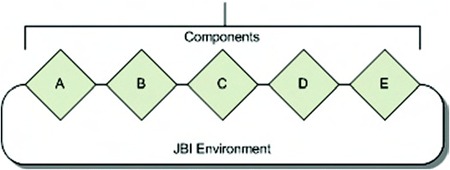
JBI defines an architecture that allows integration products to be built based on components that can be plugged into the JBI environment. These components can then provide additional services, consume services, or do both. For instance, component A could provide XSLT transformation functionality, while component B could consume incoming JMS messages. This provides a high degree of flexibility and also allows components to be reused by multiple JBI environments. In other words, JBI-compliant components that work in ServiceMix will also work in other JBI environments.
There are a number of concepts described by the JBI specification that you need to understand. In this section we describe those concepts and explain how they’re used. In upcoming chapters, when we show you more about ServiceMix, we again visit these concepts.
Let’s start by looking at a detailed overview of the JBI specification (see figure 2.6).
Figure 2.6. A high-level JBI container showing the most important concepts: the normalized message router, the service engines, and the binding components
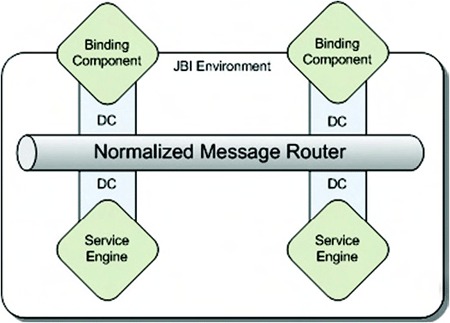
In the following sections wel explain the concepts shown in figure 2.6 in more detail. First, we look at the binding components, which handle the communication with external systems, and service engines, which contain your business logic.
2.2.1. Service engines and binding components
Service engines (SEs) and binding components (BCs) are the components in the JBI environment that provide services to other components and that allow external systems to communicate with the JBI environment. An SE provides functionality to other components and can consume services provided by other components. If you already have custom Java components that provide reusable functionality, you can easily make them available as a service engine. What you need to keep in mind, though, is that when you make a service available through an SE, only other JBI services can access this service.
In this section on JBI and the next on ServiceMix, we talk a lot about consumers and providers. Consumers and providers are the two roles a component inside a JBI container can have. If a component provides services to another component, the component’s role is the provider. If a component uses a service provided by another component, it consumes this service, and the component is called a consumer.
A good example of a provider is an XSLT service engine. This component’s role is provider, since it provides transformation services to other components. If you look at a BPEL component, a component that can orchestrate various services, you’ve got a good example of a consumer. The BPEL process consumes various services provided by other components. The BPEL process itself also provides a service to other components.
The binding component (BC) is a JBI component that provides connectivity to existing applications and services that are located outside the JBI environment. For instance, if you want to communicate with existing applications, you have to do that by using binding components. The same is true if you want to integrate with non-Java-based protocols or communication protocols (such as JMS and HTTP). Besides providing access to external services, BCs can be used to expose internal JBI services to the outside world. For instance, if you’ve got a transformation service running in an XSLT SE, you can’t access it from outside the JBI container. If you want to make this service available to the world outside the JBI container, you’ll have to use a BC to expose this service. You could, for instance, use a JMS BC to expose this service on a JMS queue.
The main thing to remember is that if you want to communicate with services outside the JBI environment or you want to allow an external application to communicate with the JBI environment, you must use binding components. For components that only provide and consume services in the JBI environment, you can use service engines.
If you dive somewhat deeper into the various interfaces and deployment descriptors associated with JBI, you’ll find out the implementation differences between an SE and a BC are minimal. It’s merely a pragmatic and conceptual distinction. The BC contains the infrastructure specific logic and the SE contains the business logic. This provides a good separation between the two different types of JBI components on a JBI container.
Besides this pragmatic distinction, there’s also an administrative distinction. JBI defines a set of Ant tasks that you can use to list information about the deployed component in your JBI environment. You can use one of these tasks to list all the SEs deployed, and another one to list the BCs deployed.
Before we go into more detail on how the components communicate with one another, take a look at figure 2.7.
Figure 2.7. This JBI container example shows service engines (SEs) and binding components (BCs) linked to the normalized message router via a delivery channel (DC).

Figure 2.7 shows a JBI container on which a couple of JBI components are installed. In this container three BCs are installed: an HTTP BC, a JMS BC, and a File BC. As you can see, each of these BCs allows communication over a certain technology. A BC doesn’t just allow incoming communications; it also provides a way for the other components in the container to communicate with external technologies.
Inside the container you see three SEs:
- An XSLT SE that can transform XML
- A BPEL SE that can be used to orchestrate services and implement a business process
- A Rules SE, which provides the functionality to execute a set of business rules
Now that we’ve seen the type of components that can exist inside a JBI container, let’s see how these components can interact with one another.
2.2.2. Services and endpoints
The following is a high-level summary of services and endpoints. This should help you grasp these concepts without having to dive too deep into the JBI specification.
We’ve mentioned that a JBI container contains a number of JBI components (BCs and SEs). What we haven’t mentioned yet is that each of these components in itself can act as a container. Let’s look again at the architecture described in figure 2.7, but now we zoom in on the XSLT SE (see figure 2.8). Remember that this SE provides us with XML transformation functionality.
Figure 2.8. XSLT SE with a number of services (XSLT style sheets) deployed

Figure 2.8 shows the XSLT SE, which is the JBI component as it’s installed in the JBI container. Four services (S1, S2, S3, and S4) are running inside this SE. Don’t worry now how to deploy services to a service engine; we explain that later in this chapter.
Each of these services executes some specific XSLT functionality. For instance, in this example S1 might transform an XML message based on a static configured XSLT file, while S2 might use a property from a message header to select the transformation to be applied.
A service can’t be accessed directly. To access a service, you need to use an endpoint. Each service must have at least one endpoint, but it can have many more. So when you want to consume a service provided by a JBI component, you need to know the name of the service and the name of the endpoint to invoke. This combination of a service and a specific endpoint on that service is called a service endpoint.
2.2.3. Normalized message router
If you look back at figure 2.6, you can see that at the center of all the components is a component called the normalized message router (NMR). This means that the JBI components (SE or BC) don’t directly communicate with each other—they communicate using the NMR. The components don’t connect directly to this NMR, but instead use a delivery channel (DC). It’s the NMR’s job to make sure that the messages are exchanged correctly among the various components in the JBI environment.
The NMR can exchange messages in a number of ways, or patterns. The following is the list of patterns that must be supported by each JBI implementation. Note that you should consider each pattern from the provider’s point of view.
- In-Only— With this pattern the consumer makes a request but doesn’t expect a response back. This also means that should a fault occur, this fault isn’t sent back to the consumer.
- Robust-In-Only— This pattern is similar to the previous one, only this time the provider can send a fault message if something goes wrong.
- In-Out— In this traditional request/reply scenario, the consumer sends a request and expects a response from the provider. If an error occurs, the provider is free to send a fault message.
- In-Optional-Out— This pattern is similar to the previous one, only this time the response is optional, and during the message interaction both parties can send a fault message.
Let’s look a bit closer at one of these exchanges. In figure 2.9 the interaction between a consumer, a provider, and the NMR is shown for an In-Out message exchange.
Figure 2.9. An overview of the communication between a consumer and a provider for an In-Out message exchange, including the communication with the normalized message router.
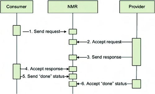
The following steps are executed here:
1. The consumer creates a message exchange for a specific service and endpoint (this combination of service name and endpoint is called the ServiceEndpoint). The consumer sets the “in” part of the message exchange with the request body. After this step, it sends the message by putting it on its delivery channel, and thus sending it to the NMR.
2. The NMR determines to which provider this exchange needs to be sent and queues it for delivery to the provider. The provider accepts this message exchange and executes its business logic.
3. After the provider has finished processing, the response message is added to the “out” part of the message exchange and the message exchange is again presented to the NMR.
4. The NMR once again queues the message for delivery to the consumer. The consumer accepts the message exchange.
5. After the response is accepted, the consumer ends this exchange by setting the status to “done.” The consumer sends the “done” response status to the NMR.
6. Finally, the provider accepts this “done” status and the complete exchange is finished.
This might look a bit complex just to send a simple message from one component to the other, but ServiceMix and the other JBI implementations as well will hide most of this complexity for you. Besides that, with the number of available service engines and binding components, you won’t often have to deal with the internals.
The message exchange patterns described here aren’t specific to JBI. The patterns are the same ones defined in the Web Services Description Language (WSDL) 2.0 specification. JBI only uses the four patterns we described earlier. However, the specification defines a couple of extra patterns (http://www.w3.org/TR/2004/WD-wsdl20-patterns-20040326) that aren’t used in JBI. As you can see from the previous patterns, they’re all written from the perspective of the provider. For instance, when we look at the In-Out pattern, the provider receives an incoming message and sends a message back to the consumer. Alternatively, the provider only receives a message and doesn’t send anything back (the In-Only pattern).
The WSDL 2.0 specification also specifies message exchange patterns the other way around. These are exchanges that are initiated by the provider and, just like the other patterns, are written from the provider point of view. So instead of the In-Only pattern, you also get the Out-Only pattern. You should consider these kinds of messages to be event messages; for instance, a certain service provider can notify its consumers that it’s going offline for an hour, or send out warnings or other events.
2.2.4. Service description, invocation, and message exchanges
We’ve talked a bit about message exchanges and you’ve seen how messages are exchanged from a high-level point of view. In this section, we dive a bit deeper into the message exchanges and explore how they’re defined and how a consumer can create a message exchange.
We’ve already talked about consumers and providers. A provider provides a certain service, and a consumer can consume that service. But how can the consumer tell what kind of operations you can invoke on a certain provider, what do the messages look like that need to be sent, and what kind of errors can you expect? There are two possible sources to get more details about the interface of a service provider. The first one is the obvious one: just look closely at the documentation and determine which operation is provided and what kind of messages can be sent. There is, however, also a more dynamic way of doing this: self-describing services.
Let’s quickly look at what the JBI specs have to say about this:
[S]ervice providers declare to the NMR the particular services they provide. Each declaration must be accompanied by a corresponding metadata definition, which describes the declaration. (This metadata definition is supplied by a Component-supplied SPI.) JBI requires that WSDL 1.1 or WSDL 2.0 be used for all such declarations. The NMR presumes (but does not enforce) that all such declarations are compliant with the WSDL specifications. However, if the metadata is malformed, it is a likely consequence that service consumers will be unable to properly invoke the service.
What this says is that each provider should publish its service description to the normalized message router as a WSDL 1.1 or WSDL 2.0 document. However, the NMR doesn’t check whether or not they are valid. Figure 2.10 illustrates the publication and consumption of services.
Figure 2.10. An overview of the publication and consumption of services via the normalized message router. A provider publishes a service on the NMR and a consumer can consume this service.
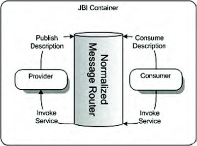
As you can see in figure 2.10, a provider can publish a service on the NMR and a consumer can consume this service. Knowing this, you can simply tell a consumer to look up the service description for a certain service endpoint and the consumer will know what kind of operations are supported and the type of messages that can be sent.
A WSDL 2.0 document is split into an abstract part and a concrete part. The abstract part defines the operations, the messages, and the XML structures a service implements. The concrete part shows how the operations can be called (such as SOAP over JMS, or by using a file in a certain directory). You can view the abstract WSDL as a Java interface definition and the concrete part as the implementation.
When you consider this from the JBI point of view, the abstract part of the WSDL is used inside the NMR. When you look up a certain description for a provider, you’ll only need the abstract part to determine how to invoke a certain service. The concrete part is often used to configure business components and service engines. For instance, Open ESB uses the concrete part of a WSDL to configure its JBI components.
Now that you know how to determine what kind of operations and messages a service provides, let’s see how a consumer can create a message exchange with a certain provider.
Invoking a certain operation on a provider isn’t that hard. You simply create a new MessageExchangeFactory for a certain service or interface. Using this factory, you create an exchange for a specific operation. Once you have the message exchange, just set the correct message and pass it on the NMR. The NMR will route the message to the correct service. This might all seem a bit complex, but you don’t have to worry. All the JBI-based ESBs out there provide a large set of components so usually you don’t have to be concerned with these internals, unless you’re writing your own SEs or BCs.
You’ve now seen how the services can communicate with one another, which roles services can have, and what service engines and binding components do. In the next section we show how you can deploy artifacts to service engines and binding components.
2.2.5. Service unit and service assembly
We’ve talked about service engines and binding components and explained that they can be containers themselves to which resources can be deployed. For instance, you could have a service engine that provides validation services and allows you to deploy XML Schemas that can be used for validation.
The resources that you can deploy to such a container are called service units (SUs). If you group these service units together, you can create a service assembly (SA), as shown in figure 2.11.
Figure 2.11. An overview of the service unit and service assembly concepts for a JBI container. A service assembly can consist of multiple service units.
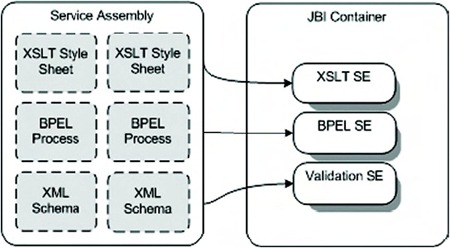
In figure 2.11 a service assembly is shown that contains multiple service units. Once this service assembly is deployed to a JBI container, each of the service units is deployed to its specific SE or BC.
The JBI specification doesn’t specify a format for these SUs and SAs, so each service engine and binding component is free to handle those in its own way. We come back to SUs and SAs in section 2.3.
2.2.6. JBI wrap-up
Let’s quickly summarize what we’ve learned about JBI so far. Table 2.5 summarizes the most important parts.
Table 2.5. The main concepts of the JBI specification
|
Component |
Description |
|---|---|
| Service engine | A JBI component that can provide services to other JBI components and can also consume services provided by other JBI components. |
| Binding component | A JBI component used to consume and provide services to services outside the JBI container. |
| Normalized message router | This component of a JBI environment takes part in delivering a message from one component to another component. This exchange always follows one of the standard message exchange patterns. |
| Delivery channel | The delivery channel connects a JBI component (a service engine or a binding component) to the normalized message router. |
| Service unit | This is an artifact that can be deployed into a running service engine or binding component. |
| Service assembly | A group of service units is called a service assembly. |
Remember, though, that JBI implementations take away much of the complexity from JBI. But it’s still important to know how JBI works internally, in case you have to solve some JBI container–related problem when implementing your integration solution.
2.3. ServiceMix architecture and components
ServiceMix is a JBI container, and therefore it provides all the infrastructure and tools required by the JBI specification. We don’t have the space to explain exactly how ServiceMix implements the JBI specification, but instead we focus on how ServiceMix allows you to easily create your own services and enables those services to communicate with one another.
2.3.1. ServiceMix overview
ServiceMix provides a list of JBI components that you can use to solve your integration problems, as you can see in figure 2.12.
Figure 2.12. Overview of a number of service engines and binding components provided by ServiceMix

The ServiceMix JBI components as shown in figure 2.12 are binding components as well as service engines. The binding components, shown above the NMR, include the servicemix-http and servicemix-file components. The service engines, shown below the NMR, include the servicemix-bean and servicemix-eip components.
Table 2.6 describes the JBI components provided by ServiceMix.
Table 2.6. The most-used JBI components provided by ServiceMix
|
Component |
Description |
|---|---|
| servicemix-bean | This service engine allows you to use POJOs as components within the JBI container. |
| servicemix-eip | ServiceMix’s EIP service engine provides various router implementations that can be used to allow more dynamic routing than the default NMR allows. The patterns in the component are based on the patterns from Hohpe and Woolf’s Enterprise Integrations Patterns book. |
| servicemix-file | This binding component allows easy access to the file system. |
| servicemix-http | This binding component allows easy access to SOAP and HTTP-based services. |
| servicemix-jms | This binding component provides access to JMS implementations like Apache ActiveMQ. |
| servicemix-camel | Camel is a routing library that contains many of the EIP patterns. This service engine allows you to use Apache Camel functionality for the routing of messages between services. |
| servicemix-cxf | Apache CXF provides us with web services support. This component, which provides an SE as well as a BC implementation, allows us to easily consume and provide web services. |
In section 2.2.5 we mentioned that service units are artifacts that can be deployed to a certain JBI component. All the components in table 2.6 support this. If you want to use the SE or BC functionality, you can deploy a service unit (which is nothing more than a JAR file containing a standard file layout) that contains an xbean.xml file.
The service unit JAR file, including the xbean.xml configuration, can be deployed to a JBI component, which will use the information configured in the service unit to create new services and register endpoints to those services. The XML data shown in listing 2.5 shows a complete xbean.xml file that can be deployed as part of a service unit to the servicemix-file binding component.
Listing 2.5. Sample XBean configuration for the ServiceMix file BC

This configuration will create a new service in the file BC with the service name esb:poller
![]() . It will also make the file BC register an endpoint with the name pollerEndpoint, through which the service can be invoked
. It will also make the file BC register an endpoint with the name pollerEndpoint, through which the service can be invoked
![]() . This service endpoint combination must be unique inside the JBI container. After this service unit is deployed, it will
be started and will monitor the inbox directory for files
. This service endpoint combination must be unique inside the JBI container. After this service unit is deployed, it will
be started and will monitor the inbox directory for files
![]() ; it will poll every 10 seconds
; it will poll every 10 seconds
![]() . Once a file is found there, it’s picked up and sent as an InOnly message exchange to the service and endpoint
. Once a file is found there, it’s picked up and sent as an InOnly message exchange to the service and endpoint
![]() specified as target service and target endpoint.
specified as target service and target endpoint.
If you look back at the examples from the Mule architecture, you’ll immediately see a big difference. Mule has chosen a generic configuration that’s used by all the different services. For Mule, it doesn’t matter whether you’re connecting over JMS or over HTTP—the configuration you use is pretty much the same. ServiceMix, however, through the means of the service units in combination with XBeans, has a unique, XML Schema–backed configuration for each technology. Apache XBean is a subproject of the Apache Geronimo application server project, which provides integration with the Spring framework. With Apache XBean you can easily define your own XML configuration language, and this is exactly what Apache ServiceMix does.
2.3.2. Routing and transformations in ServiceMix
In Mule, routing and transformation are an integral part of the architecture. Because ServiceMix itself is based on JBI, and JBI doesn’t specify anything about complex routing and transformations, it isn’t part of ServiceMix’s architecture.
Luckily, the developers of ServiceMix have provided us with a couple of options that fill in this gap. In this section, we show you a high-level overview of these options and explain how you can use them. In later chapters we describe these approaches in greater detail.
Routing using the EIP service engine
The EIP service engine provides an implementation of a number of Enterprise Integration patterns that can be used for routing. These components are used just like any of the other service engines used in ServiceMix: via an XML-based configuration. Listing 2.6 shows an XML fragment from such a configuration.
Listing 2.6. Content-based routing using the EIP service engine

In listing 2.6 we define a content-based router service
![]() . If a message is sent to this service, the service uses routing rules
. If a message is sent to this service, the service uses routing rules
![]() and
and
![]() to determine what to do with the message. In a routing rule, a number of predicates
to determine what to do with the message. In a routing rule, a number of predicates
![]() are defined. If all the predicates match, the message is sent to the specified target
are defined. If all the predicates match, the message is sent to the specified target
![]() . If no routing rules match, the message is sent to the routing rule with no predicates
. If no routing rules match, the message is sent to the routing rule with no predicates
![]() .
.
This is just one of the many routing patterns available in ServiceMix and the EIP service engine. Table 2.7 describes the routing patterns provided.
Table 2.7. The routing patterns supported by the EIP service engine provided with ServiceMix
|
Router name |
Description |
|---|---|
| Content-based router | Routes a message to a certain service based on its content. |
| Message filter | Drops a message if it doesn’t match a certain criterion. |
| Pipeline | Serves as a bridge between an In-Only message exchange pattern (MEP) and an in-out MEP. |
| Static recipient list | Sends a message to a number of different services (multicast). |
| Static routing slip | Routes a message to a number of services in sequence. |
| Wire tap | Listens in on the messages being sent on the line. |
| XPath splitter | Splits a message based on an XPath expression and routes the resulting messages to the specified service. |
| Splitter/aggregator | Combines the messages from the XPath splitter back into a single message. |
| Content enricher | Enriches the message with information from an additional service. |
| Resequencer | Resequences the order of the messages before sending them on to the target. |
Routing using Camel
Besides routing using the EIP service engine, ServiceMix can use the Apache Camel project to handle its routing. Apache Camel is a subproject of Apache ActiveMQ that implements a full set of Enterprise Integration patterns that can be configured in either Java or XML. We don’t go too deep into Apache Camel in this section; we save that for the later chapters, including chapter 5 (where we examine routing support). Just to give you a taste of the functionality of Apache Camel, the following is a quick example of how it works in combination with ServiceMix.
Apache Camel has two different configuration types. You can either write the routing rules in Java using a Java Domain Specific Language (DSL), or you configure the rules in XML. First we see how the most basic routing rule looks in Java (listing 2.7).
Listing 2.7. Camel route using Java
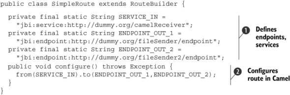
In listing 2.7 we use plain Java to configure a route. We first define a number of fully qualified names (names with namespaces)
![]() , and in the configure method, we tell Apache Camel how it should route a message. The route described in
, and in the configure method, we tell Apache Camel how it should route a message. The route described in
![]() is a basic route; it listens for messages that are sent to the service specified as SERVICE_IN and sends those messages to the endpoints defined as ENDPOINT_OUT_1 and ENDPOINT_OUT_2. So with this simple configuration we’ve implemented the recipient list pattern, where each incoming message is sent to multiple
targets.
is a basic route; it listens for messages that are sent to the service specified as SERVICE_IN and sends those messages to the endpoints defined as ENDPOINT_OUT_1 and ENDPOINT_OUT_2. So with this simple configuration we’ve implemented the recipient list pattern, where each incoming message is sent to multiple
targets.
Doing this in XML is pretty much the same as in Java, except we use a different notation (listing 2.8).
Listing 2.8. Camel route using XML
<route>
  <from uri="jbi:service:http://dummy.org/camelReceiver" />
  <to>
    <uri>jbi:endpoint:http://dummy.org/fileSender/endpoint</uri>
    <uri>jbi:endpoint:http://dummy.org/fileSender2/endpoint</uri>
  </to>
</route>
As you can see in listing 2.8, the XML is very readable and easy to understand. You once again specify where the message is coming from, and where you want it to be sent to.
With the EIP and Camel options for routing, ServiceMix provides good support for routing messages from one service (or endpoint) to the other. Next we show you how ServiceMix deals with applying transformations to messages.
Applying transformations
Transforming messages from one format to another is less important in ServiceMix (or in any other JBI container) than it is in Mule. Since the internal format used has to be XML, all the messages that are sent between the various components are guaranteed to be XML. However, XML messages also come in a lot of different flavors, so we still need message transformation. To implement transformations in ServiceMix, you can use the Saxon service engine, which uses XSLT style sheets, as shown here:
<saxon:xslt service="esb:xslt-transformation"
            endpoint="trans-endpoint"
            resource="classpath:OrderTypeAToOrderTypeB.xsl">
In addition to the Saxon service engine, ServiceMix provides an Xquery-based transformation component.
2.3.3. ServiceMix deployment models
So far we’ve mainly talked about how JBI and ServiceMix work and how all the various concepts are related to one another. Now let’s take a quick look at the various ways you can run ServiceMix.
Running ServiceMix as a stand-alone server
In this book we use ServiceMix as a stand-alone server. We’ve created an Ant target start that starts up ServiceMix and allows you to deploy artifacts to it. In this model you have to manage all resources yourself by configuring them in the servicemix.xml configuration file or by adding them to the ServiceMix-provided jndi.xml file.
Running ServiceMix from a servlet engine
ServiceMix can easily be run from a servlet engine such as Apache Tomcat since it already provides a complete web application that can be used to deploy ServiceMix as a web application to a servlet engine. In the ServiceMix distribution you’ll find an example folder; in this folder is a project named servicemix-web. This folder contains all the information you need to create a web application that starts ServiceMix.
If you want to play around with servicemix-web, you only have to use Maven to package ServiceMix into a WAR. Use the mvn package command in the root directory of this example to create a WAR file, which you can deploy to Tomcat or any other servlet engine.
The ServiceMix web application is also provided as a separate distribution download on the ServiceMix website. This WAR file can be deployed directly to a servlet engine such as Tomcat.
Running and connecting to ServiceMix from an application server
There are two options for deploying ServiceMix to an application server. The first approach is to use ServiceMix’s support for Geronimo and JBoss. In this case, ServiceMix will be tightly integrated with Geronimo and JBoss. The ServiceMix website provides tutorials that will help you to complete this integration. For the other application servers, you can use the servlet option we just explained in the servlet engine section.
2.3.4. ServiceMix wrap-up
ServiceMix makes working with JBI easier by hiding much of JBI’s complexity and providing a simple way to configure and deploy service units. In the following chapters, you’ll learn how to work with ServiceMix and create your own custom components.
2.4. Summary
This chapter showed you how easy it is to create your own components in Mule. There’s a lot more to learn about Mule, and we explore this functionality in the following chapters. Rest assured, though, that with the examples from this chapter, you now have a solid foundation to build on.
You also learned the basic concepts of JBI and explored how ServiceMix implements this specification. We promise that in the following chapters things will get easier, since we’ll start using ServiceMix and won’t have to worry much about the JBI specification details.
In the next chapter we introduce you to three technologies that we use throughout the book in our examples—Spring, JiBX, and Apache ActiveMQ—and show you how to set up an environment in which you can play around with the examples from this book.