
Chapter 9. Implementing a case study using patterns
- Overview of the Enterprise Integration patterns
- Introduction of a pattern-based design approach
- Implementing a complex case study with Mule
- Implementing a complex case study with ServiceMix
We’ve discussed a lot of different open source ESB technologies and capabilities throughout the previous chapters, but you may wonder where this leaves you when you need to implement a full-blown integration project. If you only understand the technical functionality of an open source ESB, you aren’t ready to implement an integration project from beginning to end. You need some guidance to help you with all the phases of such a project.
In this chapter, we look the different phases of an integration project, from analysis and design to the deployment of the integration solution. The main part missing from the technical foundation we’ve discussed so far is a decent design approach. Luckily, we don’t have to invent this, because a great foundational book about design patterns is available: Enterprise Integration Patterns by Gregor Hohpe and Bobby Woolf. We give you an overview of these integration design patterns and introduce a pattern-based design approach to help you in the design phase.
We use a case study about reserving restaurant tables at a large hotel to guide you through a typical integration project. We start with designing the integration solution using some of the Enterprise Integration patterns.
In addition to the project guidance we provide in this chapter, we show you some interesting functionality of Mule and ServiceMix. You’ll design the table-reservation solution and also implement an integration solution with both Mule and ServiceMix. We discuss useful functionality provided by both these tools, like the easy way to implement a publish-subscribe mechanism and the powerful routing rules available.
9.1. Introducing a design approach for integration projects
Patterns are well known in the area of application architecture and design. If you talk to Java developers and ask whether they understand the Singleton or Proxy pattern, they’ll think you’re trying to make a joke. The Gang of Four patterns are mandatory literature, or at least should be, for every object-oriented developer.
In the world of integration, the use of patterns is less common. Integration specialists are less familiar with integration patterns. Why is this? Hohpe and Woolf’s Enterprise Integration Patterns proves that a large number of patterns can be identified. Why aren’t we integration specialists using these patterns in our projects?
Most developers have a tendency to start developing without designing the solution first. The integration specialist may take the patterns into account while developing an integration solution, but the implementation still may not contain any patterns. The implementation of the message flow depends on the flow elements that the enterprise service bus product provides. ESBs generally adhere to some of the Enterprise Integration patterns, and ESB products primarily implement a selection of routing patterns. Think of the Content-Based Router and Recipient List patterns as good examples of these routing patterns.
A number of routing patterns are part of ESB product functionality and are therefore also part of the common vocabulary of integration specialists. But other categories of patterns are also valuable when you’re implementing integration solutions, such as Message Construction and Message Channel patterns. We present a restaurant case study, beginning with a pattern-based design phase and providing guidance throughout the integration project. In this section, we focus on introducing the Enterprise Integration patterns and the pattern-based design approach.
9.1.1. Introducing the Enterprise Integration patterns
Let’s do a quick recap of the Enterprise Integration patterns. For more information, you can read Enterprise Integration Patterns or visit http://www.enterpriseintegrationpatterns.com, which lists and describes all the patterns of the book in detail.
The best way to start this discussion is to look at the six pattern categories. Figure 9.1 shows them in combination with a message flow definition.
Figure 9.1. An overview of the six Enterprise Integration pattern categories from the book by Hohpe and Woolf. Each category focuses on a different aspect of a typical message flow.

The typical message flow definition shown in figure 9.1 consists of messaging elements similar to those in the examples in part 2 of this book. For example, we looked at message routing and transformation in chapter 5, and these ESB functionalities are also Enterprise Integration pattern categories. The flow definition in figure 9.1 starts with a messaging endpoint in service A. The endpoint dispatches a message that is constructed in the messaging endpoint to a message channel. Remember that a message channel can be, for example, a JMS queue, an HTTP URI, or even a file system. The message is then routed, transformed, and sent to the endpoint of service B via another message channel. The message flow is monitored with system-management patterns so you can administer the integration environment. Table 9.1 summarizes the six pattern categories.
Table 9.1. The six Enterprise Integration pattern categories
|
Pattern category |
Description |
|---|---|
| Messaging endpoints | Patterns related to the production and consumption of messages from a messaging channel. Typical examples of end-point patterns are the Idempotent Receiver and Selective Consumer patterns. |
| Messaging construction | Patterns that describe different kinds of message types and message elements. Typical examples are the Correlation Identifier and Document Message patterns. |
| Messaging channels | Ways to exchange messages between message flow elements. Typical examples are the Point-to-Point Channel and Guaranteed Delivery patterns. |
| Message routing | Ways to determine the target endpoint for an incoming message. Typical examples are the Content-Based Router and Aggregator patterns. |
| Message transformation | Patterns that transform the content of a message. Typical examples are the Message Translator and Content Enricher patterns. |
| System management | Patterns that deal with monitoring and administration functionality. Typical examples are the Wire Tap and Control Bus patterns. |
The primary advantage of the Enterprise Integration patterns is their powerful expression in a message flow design. Complex integration problems like message splitting and aggregation or content-based routing can be simplified in a message flow design with one graphical element. In the next section, we discuss a design approach based on these patterns.
9.1.2. Analyzing a pattern-based design approach
To use the Enterprise Integration patterns, you must be able to incorporate them into your integration development process. Because the pattern descriptions are combined with a graphical element notation, the patterns are perfectly suited for the design phase of an integration project. You can use the Enterprise Integration patterns like you use the Unified Modeling Language (UML) for application development projects. The Enterprise Integration patterns can also be used as a Domain Specific Language (DSL), which is growing in popularity in the software development market. (A DSL combines the powerful functionality of a modeling language with a constraint set of modeling elements based on the target domain. For example, a DSL for developing a CRUD application is different from a DSL for an integration project.)
When you’re ready to design an integration solution, you’ve already analyzed the integration problem area. This means you at least know the applications and services that are involved in the integration solution, and you know the format of the message exchanges between the applications and services. It’s also nice to be familiar with any routing rules that are applicable to the integration problem domain and to be in contact with the application’s and service’s administrators and experts.
Imagine that you have an integration domain with three services, where service A sends a message to service B or C. When the message is a purchase order, it must be sent to service B with a transformation step; and when the message is an invoice, it must be sent to service C. If the incoming message is neither a purchase order nor an invoice, it can be considered invalid. The final requirement is that the message exchange between service A and the integration solution must be reliable.
This example consists of many requirements, and it’s difficult to describe them all in one integration flow design. The Enterprise Integration patterns can help you design a simple diagram that explains the whole integration problem area; see figure 9.2.
Figure 9.2. An example of a design diagram using the Enterprise Integration patterns. The complex integration problem domain can be described in a simple diagram with the use of only six patterns.
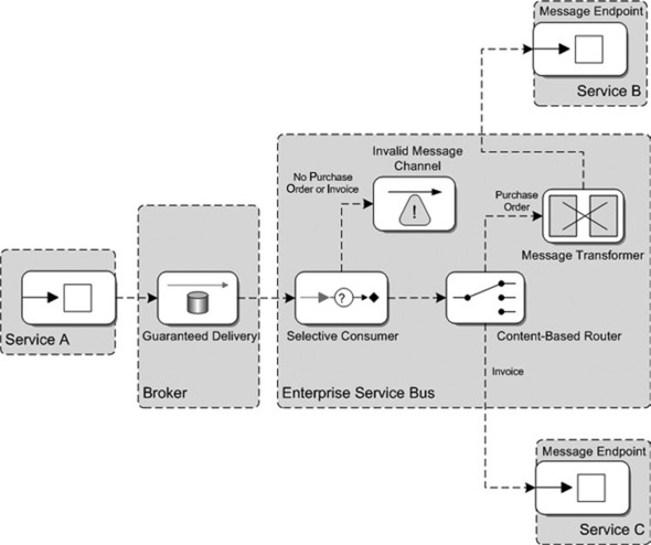
Take your time as you analyze this design diagram, because it includes six Enterprise Integration patterns, a message flow definition, and a distinction in physical domains. You can easily read the message flow definition by following the arrows. The first part of the message flow shows the Message Endpoint pattern that enables service A to send a message to a messaging infrastructure. The reliability requirement is covered by the Guaranteed Delivery pattern, which is implemented by a message broker (for example, ActiveMQ).
The functionality that is implemented by the ESB focuses on the implementation of the routing and transformation requirements. The message that is sent to the message broker is consumed by the Selective Consumer pattern, which makes it easy to only accept purchase orders and invoices. When another message type is consumed, the selective consumer sends the incoming message to an Invalid Message Channel. An ESB administrator is alerted via email or SMS message when a message arrives at the Invalid Message Channel.
Then a Content-Based Router pattern is used to route purchase orders to service B and invoices to service C, based on the content of the incoming message. This can, for example, be a message-type element or another combination of message elements to make a distinction between a purchase order and an invoice. Before the purchase order is sent to service B, the message is first transformed with a Message Transformer pattern. Eventually, the purchase order or invoice message is consumed by a message endpoint in service B or service C, respectively, which ends the message flow.
Most of this explanation can easily be determined from figure 9.2. This self-explanatory design makes it extremely useful for describing an integration problem. Another advantage of this design notation is that it’s product independent. We don’t define which ESB product we use to implement the design or which message broker we use to implement the guaranteed delivery.
It also isn’t difficult to map the design to an integration implementation solution for Mule, ServiceMix, or any other ESB product. Most of the functionality can easily be mapped onto an ESB-specific implementation element. The content-based router, for example, can be mapped onto a filtering outbound router in Mule or onto a content-based router in the EIP service engine for ServiceMix.
Now let’s use this pattern-based design approach to implement a case study in the rest of this chapter.
9.2. Introducing a restaurant table reservation case study
Suppose you’re working as an integration specialist at the SleepingBeauty hotel. The SleepingBeauty wants to offer guests an easy way to reserve a table in one of its three restaurants: Lakeview, The Royal Duck, and Yokohama.
Because all rooms are equipped with LCD televisions, the hotel manager wants to provide a simple application that lets guests reserve a table via the TV menu. A guest should be able to ask the application which restaurants have a table available for a specific number of people and at a specified time. The guest can finalize the reservation by confirming one of the offered possibilities.
Because the hotel’s restaurants are fully booked most days, the restaurant managers want to be sure that the table that’s offered to a guest is valid only for a restaurant-dependent amount of time. Each of the three restaurants has a different validity time for table offerings; these values are provided by the restaurant managers.
The project started some weeks ago, and an information analyst has already created a high-level functional design diagram of the table-reservation functionality; see figure 9.3.
Figure 9.3. Message exchanges between the actors in the restaurant table reservation case study. In this example, the hotel guest reserves a table at The Royal Duck restaurant.

The case study overview in figure 9.3 focuses on the interaction between the different actors in the case study. The hotel guest starts by entering the number of people and the dinner time in the table-reservation menu on the TV. Eventually, the hotel guest has to confirm with one of the possible restaurants to reserve the table. Then the chosen restaurant responds with an acknowledgment of the confirmation.
Although this is a simple description, the implementation of such an integration solution is complicated. The hotel manager wants you, as the SleepingBeauty integration specialist, to start the implementation right away. But because your experience with other projects has taught you that a clear and well-considered design saves time later in the project, you decide to begin with a design.
9.3. Designing the restaurant table reservation solution
The table-reservation integration solution consists of several message exchanges. It’s wise to look for request/reply exchanges and combine them into one design. By looking at figure 9.3, you can see that one message exchange asks the restaurants if a table is available. Another message exchange involves the response messages from the restaurants saying whether a table is available for the specified number of people and at the specified time.
Because these are request/reply exchanges, you can combine them into one message flow design. The confirmation exchange can then be placed in a separate message flow design to improve the readability of the diagram.
9.3.1. Designing a publish-subscribe message flow
The first thing you have to decide is how the messages should be sent to the three restaurants. From section 9.1, you know that this decision area falls under the Message Channel patterns. The two patterns in the message channel category that can solve this problem are Point-to-Point and Publish Subscribe.
With the Point-to-Point pattern solution, you introduce three new message channels, which have a fixed message producer and consumer application. The Publish Subscribe pattern seems better suited because you publish a message to a topic, and subscribed consumers can consume the message. If you want to increase the number of restaurants that participate in the table-reservation application, you can easily do so with a publish-subscribe channel. So this case study implements the publish-subscribe channel to ask the restaurants for their table availability.
To implement the response-message exchange with the restaurants, it at first seems that you don’t have to think about specific integration functionality. But if you look more closely at the requirements described in the previous section, you must consider the validity of the restaurant table availability response. When the hotel guest sends a confirmation message to reserve a table at one of the restaurants, you must be able to determine whether the confirmation message is still valid. One option would be to store the restaurant-response message with the current time in a database. You must also be able to correlate the confirmation message sent from the TV to the original restaurant response. To do so, you’ll need to add a correlation identifier to the restaurant-response message before it’s sent back to the TV menu. That Correlation Identifier pattern is part of the Message Construction pattern category.
You could use other options to determine the validity of the confirmation message. For example, you could send a validity time value in the response message to the TV and let the TV application handle the evaluation. But we’re focusing on the implementation of integration functionality in this book, and therefore we implement the validity check in the open source ESB.
At this point, you can make a design of this part of the table-reservation solution; see figure 9.4.
Figure 9.4. The message flow design diagram of the first part of the restaurant table application, using a number of Enterprise Integration patterns to visualize the integration solution
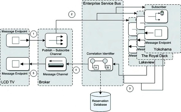
Notice that the graphical notation is similar to the example in figure 9.2, where we introduced the pattern-based design approach. The message flow starts with the message endpoint in the TV, which sends a table-availability inquiry message to a publish-subscribe message channel. Because you want the restaurant reservation applications to consume the messages from the topic, the ESB doesn’t implement any additional functionality for this message exchange. The diagram uses the Durable Subscriber pattern to show the distinction between the consumption of a message from a normal queue and a topic.
But for this case study, the Durable Subscriber pattern isn’t suitable, because the restaurant application has to respond quickly while the hotel guest is waiting; a durable subscriber means the subscriber can also be offline, and the message is delivered when the subscriber has started again. We’ve misused the graphical representation of this pattern to show that you’re implementing a subscriber on a topic instead of a messaging endpoint. We’ve done this because no better-suited Enterprise Integration pattern is available.
To implement the restaurant responses, you use the Correlation Identifier pattern. The restaurant responses are persisted into the reservation database, and the database row identifier (the primary key) is set as a message header value in the restaurant-response message. Then the restaurant-response messages are sent to a default message channel, where the table-reservation menu shows the responses to the hotel guest.
9.3.2. Designing a filtering and routing message flow
The second message flow diagram that we need to discuss addresses the confirmation of the table reservation. This includes the functionality to determine the validity of the confirmation message. When the confirmation message is consumed by the ESB, the correlation identifier is retrieved from the message header, and the reservation database is queried for the stored restaurant-response message. Then the time that has passed between the persistence of the restaurant response and the confirmation from the hotel guest is compared to the validity time specified by the chosen restaurant. Remember that each restaurant can specify its own validity time for a table reservation. Only when the validity time hasn’t been exceeded is the message sent further down the message flow.
When the message has exceeded the validity time, the message is forwarded to an invalid message channel. When the confirmation message is valid, a content-based router is used to route the message to the chosen restaurant application. The content-based router inspects the content of the message; based on the restaurant name, it determines the correct target endpoint. The TV receives a confirmation validity error message or a confirmation acknowledgment message, depending on the validity of the incoming confirmation message. Figure 9.5 shows an overview of this confirmation-message flow.
Figure 9.5. This message flow diagram shows the design of the table-confirmation message exchange. Only confirmations that haven’t timed out are accepted by the ESB. A content-based router eventually sends the confirmation message to the correct restaurant application and an acknowledgment to the TV application.
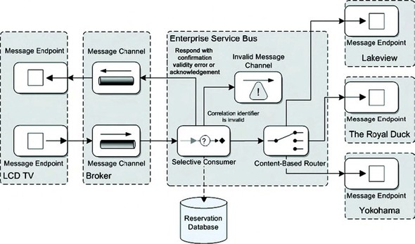
Notice that this confirmation message flow involves more functionality—which is implemented in the ESB—than the message flow we discussed in the previous section. A selective consumer is used to allow only valid confirmation messages in the remaining part of the message flow. The selective consumer queries the reservation database with the correlation identifier and determines the validity of the confirmation message.
We already discussed the remaining part of the message flow, so let’s determine the next steps. You’ve been able to design the table-reservation system with two message flow diagrams, using the Enterprise Integration patterns. Next, you’ll implement the message flows in the target platform. We show the implementation with both Mule and ServiceMix in the next section.
9.4. Implementing the case study with Mule and ServiceMix
One of the advantages of the design exercise in the previous section is that you can use it for both the Mule and ServiceMix implementations. The details of the implementations will be different, so this section is divided into three parts. We first look at the common building blocks you can use for both Mule and ServiceMix. Then we show you the details of the Mule and ServiceMix configurations separately.
9.4.1. The Spring and Hibernate building blocks
The common building blocks you need for each of the table-reservation implementations are the restaurant endpoints and the database persistency, designed in figures 9.4 and 9.5. The restaurant endpoints would in real life be reservation applications; but to simulate the interaction with these applications, you’ll implement a stub. It’s common in integration projects to implement stubs to simulate actual applications, to speed up the development process. Because Mule and ServiceMix both seamlessly integrate with Spring, we’ve chosen this container to facilitate the persistency and endpoint logic. And because Hibernate is the market standard for ORM frameworks, you’ll use this framework to build the persistency logic.
The restaurant stubs implementation
To make it easier to implement the three stubs for the restaurant-reservation applications, you’ll implement one Java bean that will be customized via dependency injection. For example, you’ll inject the restaurant name into this Java bean, so you’ll have three restaurant stubs at runtime. Listing 9.1 shows the bean implementation with the RestaurantServiceBean class.
Listing 9.1. Stub implementation for a restaurant endpoint

The restaurant stub implementation includes five attributes that will be injected by the Spring container, including the restaurant
name
![]() . These values are used to customize behavior in, for example, the calculation to see whether the reservation can be accepted.
The response that is sent back to the hotel guest can also be injected via a Spring property definition.
. These values are used to customize behavior in, for example, the calculation to see whether the reservation can be accepted.
The response that is sent back to the hotel guest can also be injected via a Spring property definition.
When the hotel guest sends an inquiry to see which restaurants have a table available, processInquiry
![]() must be invoked on this stub implementation. This means you need to implement logic in Mule and ServiceMix to invoke this
bean from a publish-subscribe mechanism, as designed in figure 9.4. You’ll see how you can easily configure this functionality later in this chapter when we discuss the Mule and ServiceMix
configurations.
must be invoked on this stub implementation. This means you need to implement logic in Mule and ServiceMix to invoke this
bean from a publish-subscribe mechanism, as designed in figure 9.4. You’ll see how you can easily configure this functionality later in this chapter when we discuss the Mule and ServiceMix
configurations.
This stub implementation is kept simple, but you implement one piece of logic to determine whether a table is available for
the requested number of people
![]() . This is a simplification of the table-reservation process, but we’re focusing on integration logic and not on the application
logic.
. This is a simplification of the table-reservation process, but we’re focusing on integration logic and not on the application
logic.
Defining the reservation database model
The other common building block is the persistency of the reservation, which lets you correlate the restaurant response to the confirmation message and calculate the validity of the confirmation message. To implement the persistence layer, you’ll use an HSQL database. This database doesn’t require a difficult installment procedure and is ready to go when you download the open source product. You’ll use two simple tables to persist the reservation between the restaurant response and the guest’s confirmation message, as shown in figure 9.6.
Figure 9.6. This is the database model for the restaurant-reservation case study; it enables the persistence of reservations. The Reservation table stores the restaurant reservation responses, and the Restaurant table holds the three restaurants with timeout values.
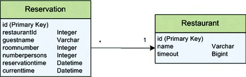
The Reservation table stores all the restaurant-response messages that are sent to hotel guests. You store the restaurant identifier and the current time with the guest information values. The current time value and the restaurant timeout value provide enough information to calculate the validity of the confirmation message. The identifier of the reservation table is used to correlate the restaurant-response message with the confirmation message. The Restaurant table holds the three restaurants with their names and corresponding timeout values, which are provided by the restaurant manager.
Implementing the reservation data logic
Now that you’ve defined the database model, you can implement the ORM logic with Hibernate. We won’t go into detail about how to use the Hibernate framework, because two excellent books have been written about this topic by Hibernate’s founders: Java Persistence with Hibernate(Manning: Christian Bauer and Gavin King, 2006) and Hibernate in Action(Manning: Christian Bauer and Gavin King, 2004). And because the ORM definition of these two tables is fairly simple, listing 9.2 shows the DAO that you’ll use in the Mule and ServiceMix implementations. Remember that the entire example, including the mapping definition, is available at http://www.manning.com/rademakers and at http://www.esbinaction.com.
Listing 9.2. DAO to retrieve and store reservations; implemented with Hibernate
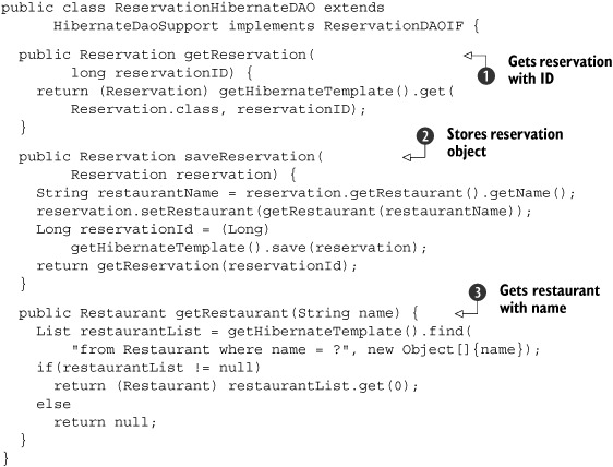
If you’re familiar with the Hibernate framework, this DAO implementation class won’t be difficult to understand. You use the Hibernate support class HibernateDaoSupport of the Spring Framework to handle the database connections and transactions, so you only have to implement the data-retrieval and -manipulation logic.
When the message flow in the ESB receives a confirmation message from the hotel guest, you need to retrieve the reservation
based on the reservation identifier. The getReservation
![]() method implements this functionality in only one line of code.
method implements this functionality in only one line of code.
You also need to persist a Reservation object to the HSQL database, so you implement the saveReservation method
![]() . Because the message flow only sets a restaurant name in the Reservation object, you need to implement another method to retrieve the Restaurant object, including the restaurant identifier
. Because the message flow only sets a restaurant name in the Reservation object, you need to implement another method to retrieve the Restaurant object, including the restaurant identifier
![]() . Then the reservation can be persisted to the database.
. Then the reservation can be persisted to the database.
With these common building blocks in place, we can now look at the integration logic that you’ll need to implement with Mule.
9.4.2. Implementing the Mule message flow
In the design phase, you separated the functionality into two design diagrams. This is also a good starting point for the implementation phase.
Implementing a publish-subscribe mechanism with Mule
The first part of the functionality involves implementing a publish-subscribe mechanism with the restaurant endpoints. You implemented a stub class to simulate the restaurant endpoints in the previous section; now you need to decide how you can use this class in your message flow implementation. Because you’re using Spring as an object container for the restaurant endpoints, you can easily reference these beans from a Mule service definition. You must define three Mule services that are subscribed to a specific topic, which invoke the Spring beans that represent the restaurant endpoints. Figure 9.7 provides an overview of this publish-subscribe implementation for Mule.
Figure 9.7. The publish-subscribe implementation in the Mule message flow definition. Three topic subscribers are defined; they invoke the restaurant beans that simulate the restaurant reservation applications.
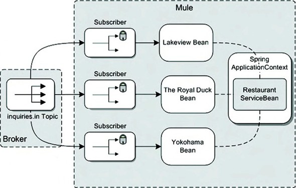
Notice that you define three subscribers in the Mule configuration. This is different than the diagram in figure 9.4, due to the stub implementation of the restaurant endpoints. Stubs are useful in real-life projects, especially early on. But be sure to clarify the specification of the interface with the actual target applications as early as possible. The stub implementation should reflect the interface of the real target application. Figure 9.7 also shows the instantiation of the restaurant beans from the same restaurant service bean class, RestaurantServiceBean, which you implemented in listing 9.1. Listing 9.3 shows one of the subscriber service definitions configured in the Mule configuration.
Listing 9.3. Topic subscriber that invokes the restaurant bean

In addition to the definition of the publish-subscribe mechanism as shown in figure 9.7, this Mule configuration also describes the restaurant-response implementation shown earlier in figure 9.4. But let’s first focus on the publish-subscribe functionality, because it’s also the starting point for the message flow.
The Mule configuration can become large, so it’s a good practice to separate logical units of work in different files. You
need to define the Spring restaurant beans and the Hibernate DAO in addition to the Mule message flow, so you’ll divide these
definitions into two files. It’s easy to combine the two definitions with a simple import statement
![]() . You can configure multiple import statements if necessary.
. You can configure multiple import statements if necessary.
Because you want to implement three topic subscribers in this Mule configuration, you must first define a JMS connection
![]() . You don’t have to configure anything special to be able to subscribe to a topic, so you configure a default JMS connector.
. You don’t have to configure anything special to be able to subscribe to a topic, so you configure a default JMS connector.
To be able to reuse the topic endpoint definition for all three topic subscribers, Mule provides an option to define a reusable
endpoint at the root level of the Mule configuration
![]() . You can refer to the reusable endpoint with the inquiry-topic name. The JMS endpoint definition uses a prefix of topic:, which tells Mule that the JMS endpoint is a topic.
. You can refer to the reusable endpoint with the inquiry-topic name. The JMS endpoint definition uses a prefix of topic:, which tells Mule that the JMS endpoint is a topic.
This Mule configuration defines just one of three restaurant subscribers, because the other two use the same configuration.
The inbound router listens for new messages arriving at the topic endpoint. Because you eventually want to send the restaurant-response
message to the JMS ReplyTo destination that is set in the incoming JMS message arriving at the topic, you use the remoteSync value of true in this configuration
![]() .
.
The remoteSync attribute tells the Mule container to wait for a response on the outgoing message before responding to the incoming message. You can find information about the remoteSync attribute at http://www.mulesource.org/display/MULE2USER/Messaging+Patterns (login required). For this example, you want to send three restaurant-response messages to the TV application based on the JMS ReplyTo destination header value. Mule uses the ReplyTo destination transparently, without the need to define additional configuration parameters.
When you don’t specify the remoteSync attribute, no response message is sent to the queue specified with the JMS ReplyTo header. By specifying the remoteSync value of true, the expirationBean response message is sent back to the LakeViewRestaurantService Mule service. So the response message of the expirationBean is processed by the LakeViewRestaurantService and sent to the destination defined by the JMS ReplyTo header value.
When the JMS message has been consumed from the inquiries.in topic, the Mule container invokes the restaurant service bean
![]() . For the Lakeview topic subscriber, this means the Spring bean that is configured as the Lakeview stub implementation is
invoked. The Lakeview restaurant service bean is configured in the restaurant-beans.xml file that you import
. For the Lakeview topic subscriber, this means the Spring bean that is configured as the Lakeview stub implementation is
invoked. The Lakeview restaurant service bean is configured in the restaurant-beans.xml file that you import
![]() .
.
This concludes the definition of the publish-subscribe mechanism, but the Mule configuration example also shows the restaurant-response
functionality. The restaurant responses are sent back to the hotel guest via the JMS ReplyTo header value. Before the message is sent, you need to add a correlation identifier to the outgoing message as designed in
figure 9.4. This functionality is implemented with the ExpirationBean Spring bean, which is also imported from the restaurant-beans.xml Spring configuration
![]() . We look at the implementation of this Spring bean in detail in listing 9.4. Because you need to store the restaurant-response message, you also inject the ReservationHibernateDAO class instance from listing 9.2 in this outbound router.
. We look at the implementation of this Spring bean in detail in listing 9.4. Because you need to store the restaurant-response message, you also inject the ReservationHibernateDAO class instance from listing 9.2 in this outbound router.
To set the restaurant identifier in the outgoing response message, you use a custom JMS header field named restaurantResponseID. The custom header field includes the reservation database identifier from the restaurant response in the confirmation message, which is sent back from the TV application. The details of the expiration Spring bean are shown in listing 9.4.
Listing 9.4. Expiration bean that stores the reservation message
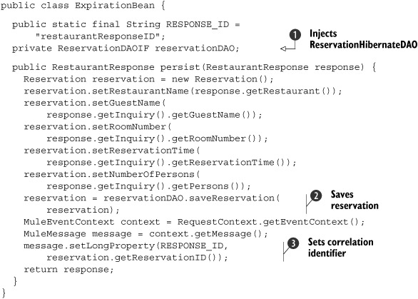
The reservation DAO is injected in the ExpirationBean via the reservationDAO attribute
![]() . The RestaurantResponse message returned by the restaurant service bean consists of the restaurant name, a response message, and a Boolean value
to indicate whether a table can be reserved. The response message also includes the inquiry message, which was received from
the topic. To store the reservation, you need a restaurant name, the current time, and a number of guest-related values, as
you may recall from figure 9.6. Because the current time is automatically set when a new Reservation object is instantiated, you only copy the other values. Then the Reservation instance can be persisted into the HSQL database via the Hibernate DAO
. The RestaurantResponse message returned by the restaurant service bean consists of the restaurant name, a response message, and a Boolean value
to indicate whether a table can be reserved. The response message also includes the inquiry message, which was received from
the topic. To store the reservation, you need a restaurant name, the current time, and a number of guest-related values, as
you may recall from figure 9.6. Because the current time is automatically set when a new Reservation object is instantiated, you only copy the other values. Then the Reservation instance can be persisted into the HSQL database via the Hibernate DAO
![]() .
.
The saveReservation message returns the database-persisted Reservation values, which include the generated reservation identifier. This reservation identifier can now be set as a header property
in the Mule message
![]() . The header properties are automatically copied to the outgoing JMS message and returned to the TV reservation application.
. The header properties are automatically copied to the outgoing JMS message and returned to the TV reservation application.
With the publish-subscribe functionality in place, you can now implement the confirmation message functionality, which includes both a message filter and a content-based router implementation.
Implementing the routing functionality with Mule
The second part of the Mule configuration for the restaurant reservation application handles the confirmation message that the hotel guest sends to his or her chosen restaurant. You need to implement functionality that checks whether the confirmation message is still valid, and you must also determine which restaurant application is the target endpoint for the confirmation message. The best way to start the implementation of this functionality is to define the Mule configuration for this message flow. After that, you can implement the remaining functionality: in this case, the confirmation-validity check. Let’s first look at the Mule configuration for the routing functionality, shown in listing 9.5.
Listing 9.5. Mule definition of the confirmation-message routing functionality

The service that is configured in this example is part of the Mule configuration defined in listing 9.3. But to clarify the message flow, the configuration is split into two listings. The inbound router listens for confirmation
messages arriving at the reservation.confirmation queue
![]() . Again, you configure a remoteSync attribute value of true to use the JMS ReplyTo header value after the second service. If you didn’t configure the remoteSync attribute value of true, no reply message would be sent to the JMS queue provided with the JMS ReplyTo header. Notice that even if you define an outbound router on the second Mule service, in this case the reservationResponse-Service, the response message of the component, in this case the confirmationBean, is also sent back to the inbound endpoint with the remoteSync attribute.
. Again, you configure a remoteSync attribute value of true to use the JMS ReplyTo header value after the second service. If you didn’t configure the remoteSync attribute value of true, no reply message would be sent to the JMS queue provided with the JMS ReplyTo header. Notice that even if you define an outbound router on the second Mule service, in this case the reservationResponse-Service, the response message of the component, in this case the confirmationBean, is also sent back to the inbound endpoint with the remoteSync attribute.
When a confirmation arrives, the validity of the message is checked with the ExpirationCheckFilter
![]() . We look at the details of this filter in listing 9.6. Because you need to retrieve the persisted reservation based on the reservation identifier that is part of the confirmation
message, the ReservationHibernateDAO class is injected in the filter instance.
. We look at the details of this filter in listing 9.6. Because you need to retrieve the persisted reservation based on the reservation identifier that is part of the confirmation
message, the ReservationHibernateDAO class is injected in the filter instance.
Because you also need to deal with confirmation messages that are no longer valid, you implement a catch-all strategy
![]() , which is invoked when the filter rejects the incoming JMS message. For this example, the invalid confirmation message is
sent to a JMS queue, but in real-life implementations you could implement additional functionality here.
, which is invoked when the filter rejects the incoming JMS message. For this example, the invalid confirmation message is
sent to a JMS queue, but in real-life implementations you could implement additional functionality here.
When the confirmation message is checked for validity, you need to forward it to the correct restaurant endpoint. In this
example, you have three JMS queues, which represent the different restaurant applications. With a content-based routing implementation
based on a filtering outbound router, you can forward the confirmation to the right JMS queue
![]() . In the confirmation bean, the restaurant name is set as a message-header value. The message header choice is used to store the restaurant name. Therefore, you can use the message-property filter to implement the content-based router.
The message-property filter evaluates the pattern attribute against the message headers in the outgoing message, which in
this example is the Restaurant-Confirmation message.
. In the confirmation bean, the restaurant name is set as a message-header value. The message header choice is used to store the restaurant name. Therefore, you can use the message-property filter to implement the content-based router.
The message-property filter evaluates the pattern attribute against the message headers in the outgoing message, which in
this example is the Restaurant-Confirmation message.
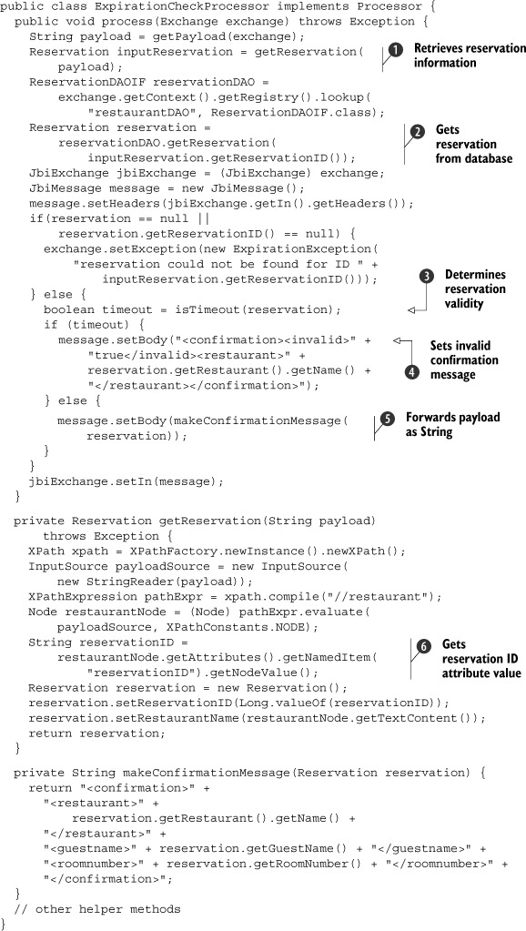
The only part you need to implement to complete this integration solution is the filter to check the validity of the confirmation message. You check the time that has passed between the restaurant response and receipt of the confirmation message with the timeout value specified in the database for the chosen restaurant. The Java code implementation of the filter is shown in listing 9.6.
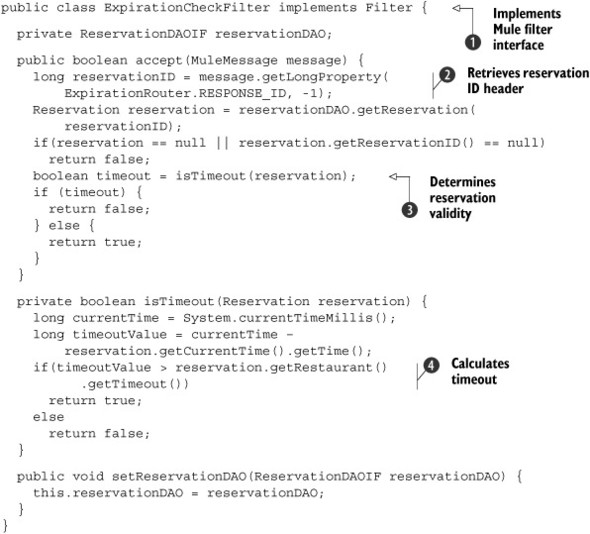
Listing 9.6. Filter implementation validating the confirmation message
Because you only want to allow confirmation messages that haven’t exceeded the timeout value specified in the database for
the chosen restaurant, you need a filter mechanism. Within Mule, this is easy to do by implementing the Filter interface
![]() . Implementing the Filter interface means implementing the accept method. When a Boolean value of true is returned, this means the filter accepts the message; if the value is false, the message is rejected.
. Implementing the Filter interface means implementing the accept method. When a Boolean value of true is returned, this means the filter accepts the message; if the value is false, the message is rejected.
Because you want to check the time that has passed between the restaurant response and the confirmation message, you need
to get the reservation identifier to retrieve the persisted time value. The reservation identifier is passed as a header property
in the confirmation message, so you can easily retrieve this value
![]() .
.
With the reservation identifier, you can retrieve the reservation from the HSQL database via the injected Hibernate DAO class.
The last step is to compare the time that has passed between the restaurant response and the confirmation message and the timeout value that is specified for the chosen restaurant
![]() . This is an easy calculation given the time values retrieved from the database and the current time value
. This is an easy calculation given the time values retrieved from the database and the current time value
![]() .
.
You’ve implemented all the parts of the restaurant reservation solution in Mule. Because you started designing the integration solution by using Enterprise Integration patterns, you saw that the translation to an actual implementation isn’t that difficult. You had to make some decisions about how to implement the publish-subscribe and selective-consumer functionality, but the foundation of the solution hasn’t changed. More information about how to run this restaurant example on the Mule container can be found in section 9.5.1.
For the ServiceMix implementation of this case study, you’ll have to make similar decisions. But you’ll see that other options are available to implement the example, and this will help you on your quest to become an open source ESB specialist.
9.4.3. Implementing the ServiceMix message flow
You’ll implement the same table reservation case study with ServiceMix as you did in the previous section with Mule. You’ll see that the design that you made in section 9.3 is also great as a foundation for the ServiceMix implementation. You’ve kept the design product and technology neutral and therefore it’s applicable for multiple ESB implementations. To make it easier to understand the ServiceMix integration solution, we split the solution description into a publish-subscribe and a filter and routing part just like you did for the Mule implementation.
Implementing a publish-subscribe mechanism with ServiceMix
The implementation of the publish-subscribe functionality in ServiceMix involves configuring a number of JBI components. You’ll need to configure some JMS endpoints within the JMS binding component, but the incoming JMS messages also need to be routed to the three restaurant Spring beans you implemented in listing 9.1.
It’s no problem to integrate Spring beans in a ServiceMix message flow, but you have to think about the marshaling and unmarshaling of the XML messages that flow through the JBI bus to the Java beans that are defined as the input parameters and return value for the Spring restaurant bean. Two components are applicable to implement the Spring bean invocation: the Bean service engine and the JSR-181 service engine. You’ll use the JSR-181 service engine, because this component is capable of (un)marshaling the XML messages automatically. But the JMS binding component and the JSR-181 service engine are not the only JBI components you need: you also need to deal with routing the incoming message to the restaurant beans and handling the restaurant responses. This functionality will be implemented with the Camel service engine. Figure 9.8 shows all the JBI components required for the first part of the integration solution.
Figure 9.8. JBI components that are needed to implement the publish-subscribe functionality for the table reservation integration solution in ServiceMixBecause you’ll use in-out JMS consumers, which consume messages from the inquiries.in topic and produce messages to the reply-to queue specified in the JMS ReplyTo header, you don’t have to use the pipeline EIP component.
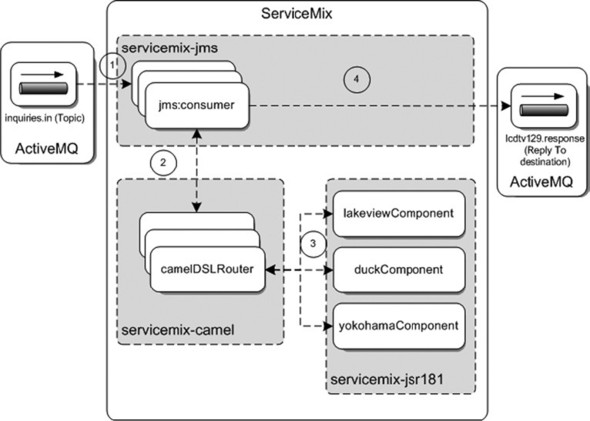
Figure 9.8 also shows the use of the Camel service engine. Why do you need this component? You also need to add a correlation identifier to be able to correlate the restaurant response to the confirmation message sent by the hotel guest. You use a Camel DSL router to invoke the JSR-181 component and handle the restaurant response by adding a correlation identifier to the outgoing restaurant-response message. You could also implement this functionality with a Bean service engine component, but the Camel framework provides some nice features, as you’ll see later in listing 9.9.
You already saw how to configure JMS endpoints in a number of examples; listing 9.7 shows only one of the three JMS topic endpoints that you need in the solution implementation.
Listing 9.7. JMS endpoint configuration that listens for messages

The difference between a queue listener and a topic subscriber is the pubSubDomain attribute value
![]() . For topic subscribers, you have to specify a value of true for this attribute.
. For topic subscribers, you have to specify a value of true for this attribute.
The listing shows that this is a topic subscriber for the Lakeview restaurant. In figure 9.8, you saw that the message retrieved from the topic is forwarded to a Camel DSL router, which in this case is the Lakeview
DSL router
![]() .
.
Because you want the consumer to use an in-out exchange pattern, you have to configure a marshaler bean
![]() . By default, the JMS consumer endpoint uses the DefaultConsumerMarshaler class, which is provided by the ServiceMix JMS binding component. The default marshaler uses an in-only exchange pattern.
In addition, you need to send the response message received from the DSL router to the queue specified in the JMS ReplyTo header of the incoming topic message. This functionality is also implemented in the custom ReplyToConsumerMarshaler class. Listing 9.8 shows the implementation of this class.
. By default, the JMS consumer endpoint uses the DefaultConsumerMarshaler class, which is provided by the ServiceMix JMS binding component. The default marshaler uses an in-only exchange pattern.
In addition, you need to send the response message received from the DSL router to the queue specified in the JMS ReplyTo header of the incoming topic message. This functionality is also implemented in the custom ReplyToConsumerMarshaler class. Listing 9.8 shows the implementation of this class.
Listing 9.8. ReplyToConsumerMarshaler class implementation

Because you extend the DefaultConsumerMarshaler class, you can override the method where the ServiceMix normalized message is populated with the content of the incoming
JMS message
![]() . In this case, the incoming message is the restaurant inquiry message, which contains the guest name, room number, number
of people, and reservation time.
. In this case, the incoming message is the restaurant inquiry message, which contains the guest name, room number, number
of people, and reservation time.
Because you want to send the restaurant-response message to the JMS ReplyTo header destination, you need to extract this header from the JMS message
![]() . This is easy; you can call the getJMSReplyTo method on the JMS message instance. Then you set this reply-to destination in the ServiceMix normalized message.
. This is easy; you can call the getJMSReplyTo method on the JMS message instance. Then you set this reply-to destination in the ServiceMix normalized message.
The ServiceMix JMS binding component uses a SimpleDestinationChooser by default to determine the target destination for an outgoing JMS message. This destination-chooser class is part of the ServiceMix JMS binding component and looks for a property in the normalized message header that’s equal to the DESTINATION_KEY of the SimpleDestinationChooser class. When such a header is present, the JMS BC uses the value of this destination property as the target destination for the outgoing JMS message. When the destination header isn’t present, the JMS endpoint looks for a statically configured destination value: for example, the destination configured with the destinationName attribute.
You set the reply-to destination on the message header of the normalized message. Because you specify that the JMS consumer uses an in-out message exchange pattern, the restaurant response message is returned to the JMS consumer. The Simple-DestinationChooser class inspects the response message for a destination header and uses this value as the target destination of the response message. The restaurant-response message is sent to the JMS ReplyTo header destination specified with the restaurant inquiry message.
Adding a correlation identifier with Apache Camel
Now let’s move on to the next JBI component in the message flow: the Camel service engine. The three Camel components implement the most functionality of the publish-subscribe solution. First, the Camel router invokes the restaurant Spring bean via a JSR-181 endpoint; second, the Camel router adds a correlation identifier before the message is routed to the outgoing JMS endpoint. Listing 9.9 shows the Camel service engine configuration and the Lakeview Camel router.
Listing 9.9. Camel service engine with a router implementation

Listing 9.9 shows the configuration of the Camel service engine, camel-context.xml, at the top and below the Lakeview Camel router implementation. The only difference from the other restaurant Camel routers is the service-name configuration.
To be able to add a correlation identifier to the restaurant-response message, you first need to persist the reservation to
the HSQL database with the Hibernate DAO from listing 9.2. The Hibernate bean configuration is split into a separate Spring bean file, which is imported in the Camel service engine
configuration
![]() .
.
For this implementation, you’re implementing the router with the Java Camel DSL instead of the Spring XML configuration. So
the Camel service engine configuration is short, and you only need to define the packages where the Camel router classes can
be found
![]() . When the Camel context is started, the Camel container instantiates the router classes that are available in the esb.chapter9.restaurant.camel package.
. When the Camel context is started, the Camel container instantiates the router classes that are available in the esb.chapter9.restaurant.camel package.
In the Camel router implementation, the routing rules are specified in the configure method, which is invoked by the Camel
container. The routing rule definition starts with the service-name definition for the Camel router, so it can be invoked
from the ServiceMix JBI container
![]() . The service name lakeviewDSLRouter corresponds to the transformer-exchange target specified as the target service for the JMS consumer configuration in listing 9.7.
. The service name lakeviewDSLRouter corresponds to the transformer-exchange target specified as the target service for the JMS consumer configuration in listing 9.7.
An InOutProcessor is defined as the first processor for the incoming message
![]() . This processor is needed because the ServiceMix JBI and the Camel exchange have different views of message exchange patterns.
In the ServiceMix container, message-exchange patterns are important definitions, because they specify whether a response
message can be expected. Camel has a less strict definition of exchanges. In the JMS consumer definition in listing 9.7, you specify an In-Out Message Exchange pattern; but in the Camel router, this exchange pattern isn’t copied from the ServiceMix
message exchange and therefore the exchange pattern is equal to null. In the InOutProcessor, you must specify that the exchange is an in-out exchange so the outgoing message exchange to the JSR-181 component uses
an in-out message exchange pattern. The implementation of the InOutProcessor is as follows:
. This processor is needed because the ServiceMix JBI and the Camel exchange have different views of message exchange patterns.
In the ServiceMix container, message-exchange patterns are important definitions, because they specify whether a response
message can be expected. Camel has a less strict definition of exchanges. In the JMS consumer definition in listing 9.7, you specify an In-Out Message Exchange pattern; but in the Camel router, this exchange pattern isn’t copied from the ServiceMix
message exchange and therefore the exchange pattern is equal to null. In the InOutProcessor, you must specify that the exchange is an in-out exchange so the outgoing message exchange to the JSR-181 component uses
an in-out message exchange pattern. The implementation of the InOutProcessor is as follows:
public class InOutProcessor implements Processor {
  public void process(Exchange e) {
    JbiExchange exchange = (JbiExchange) e;
    exchange.setPattern(ExchangePattern.InOut);
  }
}
The second part of the routing rule specifies a target endpoint for the received message. This target endpoint is the JSR-181 service name for the restaurant Spring bean. When a response is received from the Spring bean, the correlation identifier is added in the ExpirationProcessor class. This processor lets Camel change the message exchange when required. You use the processor class to add a correlation identifier to the response message. Listing 9.10 shows the implementation of the ExpirationProcessor class.
Listing 9.10. ExpirationProcessor implementation, adding a correlation identifier
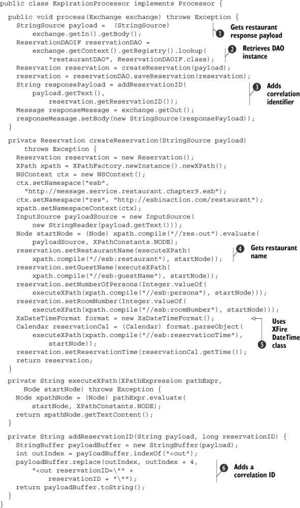
This processor implementation performs the main part of the publish-subscribe and correlation-identifier functionality. The
Processor interface prescribes the implementation of the process method, which gets the message exchange as an input parameter. The
implementation of this processor starts with the retrieval of the restaurant-response message
![]() . Because every message flowing through the JBI container is an XML message, you know that the payload content is an XML String. In ServiceMix, this means the payload is an instance of the StringSource class.
. Because every message flowing through the JBI container is an XML message, you know that the payload content is an XML String. In ServiceMix, this means the payload is an instance of the StringSource class.
You saw in listing 9.9 that the Hibernate DAO, which you use to persist the restaurant-response message, is imported in the Camel configuration.
Because you use a Spring context loader to start the Camel context, you can retrieve the Hibernate DAO instance via the registry
instance in the Camel context
![]() . The registry is implemented with a Spring registry class, so you can do a lookup for a bean with the identifier of restaurantDAO.
. The registry is implemented with a Spring registry class, so you can do a lookup for a bean with the identifier of restaurantDAO.
Before you can persist the reservation to the database, you first need to retrieve the restaurant and guest information from
the restaurant-response message. Instead of an XML-to-Java deserializer like JiBX, you use XPath expressions to get the information
from the response message. An example of retrieving such an element is the XPath expression for the restaurant name
![]() .
.
Another example of an XPath expression is the retrieval of the reservation time. Because this is a DateTime value, you need to deserialize the element value to a Java Calendar object. The response message is received from the JSR-181 component, which we discuss
later in this section, so the XML serialization is implemented with XFire and the Aegis binding. Because the DateTime serialization is implemented with a custom XFire and Aegis binding class, XsDateTimeFormat, you use this class to deserialize the DateTime value
![]() .
.
With the Hibernate DAO and the restaurant and guest information retrieved, you can now store the reservation object in the
HSQL database. The database identifier of the reservation table is used to correlate the restaurant-response message to the
confirmation message sent by the hotel guest; you can add this identifier to the message
![]() .
.
Because the JMS binding component doesn’t provide functionality to copy a custom header from a JBI message to a JMS message,
you need another solution to pass the correlation identifier back to the TV reservation application. You implement a quick-and-dirty
way to add the reservation identifier to the response message as an attribute
![]() .
.
One part of the publish-subscribe functionality remains to be implemented: the configuration of the JSR-181 service engine. But with the Camel component implemented, this should be a piece of cake. The JSR-181 endpoint is a wrapper to marshal and unmarshal the input and output XML messages for the restaurant Spring bean. Listing 9.11 shows one of the JSR-181 restaurant endpoints.
Listing 9.11. JSR-181 endpoint to wrap the restaurant Spring bean
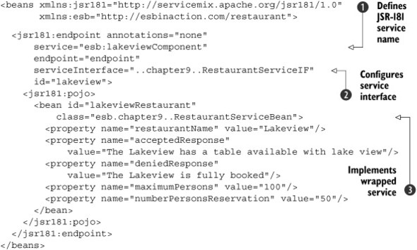
The configuration of a JSR-181 endpoint starts with the definition of unique service and endpoint names for the identification
inside the JBI container, like any other JBI component
![]() . The service name of the Lakeview JSR-181 component corresponds with the target endpoint for the Camel router shown in listing 9.9.
. The service name of the Lakeview JSR-181 component corresponds with the target endpoint for the Camel router shown in listing 9.9.
You configure the interface that must be used when calling this endpoint with the serviceInterface attribute
![]() . RestaurantServiceIF specifies a processInquiry method, which expects a number of persons and a time parameter. This interface is transformed with the JSR-181 implementation
into a WSDL counterpart, so that it can be used in the ServiceMix JBI container.
. RestaurantServiceIF specifies a processInquiry method, which expects a number of persons and a time parameter. This interface is transformed with the JSR-181 implementation
into a WSDL counterpart, so that it can be used in the ServiceMix JBI container.
You can configure the service implementation in the pojo element with a normal Spring bean configuration
![]() . With the property definitions, the RestaurantServiceBean is instantiated as a Lakeview restaurant endpoint. The implementation of the RestaurantServiceBean was discussed in listing 9.1.
. With the property definitions, the RestaurantServiceBean is instantiated as a Lakeview restaurant endpoint. The implementation of the RestaurantServiceBean was discussed in listing 9.1.
You’ve covered a lot of functionality with the implementation of the first part of this solution, but you also need to implement the routing and filtering logic to handle the confirmation message from the hotel guest. The next section focuses on implementing a message filter and content-based routing functionality without introducing other JBI components to the integration solution.
Implementing the routing functionality with ServiceMix
In this section, we dive deeper into the Camel component as you implement filter, content-based routing, and error-handling logic. Let’s start with a recap of what you need to implement according to the requirements from the design in section 9.3.
The hotel guest is presented with a number of restaurants that have a table available for this evening. When the guest chooses to confirm one the table reservations, a confirmation message is sent by the reservation application to the ServiceMix ESB. The ServiceMix message flow must first check the validity of the confirmation message with the persisted reservation and then route the confirmation to the correct restaurant endpoint if the message is still valid. If the confirmation message has timed out, the message is sent to an error queue. Figure 9.9 provides an overview of the message flow you need to implement and categorizes the functionality against the involved JBI components.
Figure 9.9. The ServiceMix message flow and the involved JBI components for the implementation of the confirmation message handler

The message flow shows that you use only two JBI components: Camel and JMS. The JMS component receives and sends JMS messages outside the JBI container, but the most interesting functionality is implemented in the Camel component. Listing 9.12 shows the Camel router implementation.
Listing 9.12. Expiration Camel filter and content-based router implementation
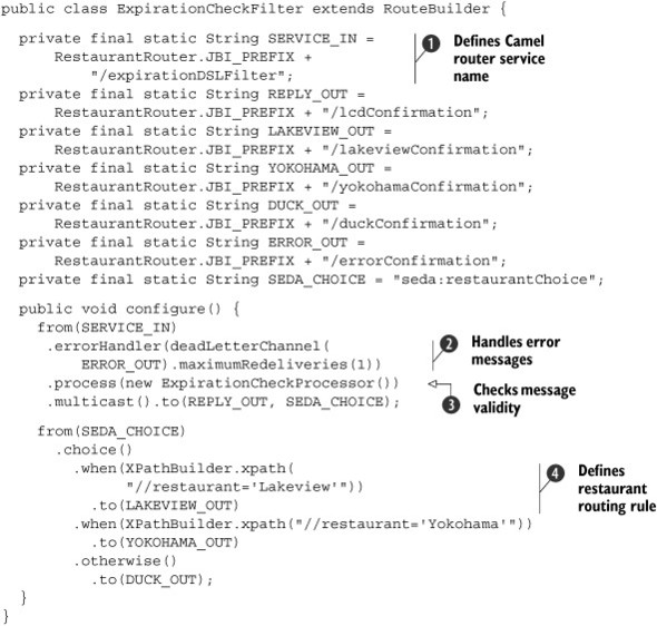
The implementation of the expiration Camel router starts with defining a number of JBI endpoints that are used in the routing
implementation. One of the JBI endpoint definitions configures the service name for this Camel router
![]() . The expiration-DSLFilter service name is configured as the target service for the JMS consumer end-point, where the confirmation messages arrive.
. The expiration-DSLFilter service name is configured as the target service for the JMS consumer end-point, where the confirmation messages arrive.
The routing configuration starts with the definition of an error handler to handle exceptions that occur in the expiration
processor
![]() . The error handler specifies that the confirmation message must be redelivered only once and then sent to a JMS error endpoint.
. The error handler specifies that the confirmation message must be redelivered only once and then sent to a JMS error endpoint.
The logic to check whether a confirmation message is still valid is implemented in the ExpirationCheckProcessor
![]() . This processor implementation is invoked first when a messages is sent to this Camel router service. We explain this implementation
after listing 9.13. When the reservation identifier in the confirmation message isn’t valid, the expiration processor returns an error message,
as you’ll see in the implementation of the processor. A reservation timeout or a valid reservation results in a confirmation
message being sent to the chosen restaurant and the TV application with the multicast method.
. This processor implementation is invoked first when a messages is sent to this Camel router service. We explain this implementation
after listing 9.13. When the reservation identifier in the confirmation message isn’t valid, the expiration processor returns an error message,
as you’ll see in the implementation of the processor. A reservation timeout or a valid reservation results in a confirmation
message being sent to the chosen restaurant and the TV application with the multicast method.
When the expiration processor has evaluated the validity of the message, the target restaurant endpoint is determined. This
functionality is implemented with a number of content-based routing rules
![]() . With the XPathBuilder class, you have an easy-to-use mechanism to use XPath expression in your routing rules. The routing rules defined in this
example use the restaurant name in the message content to determine the correct target endpoint.
. With the XPathBuilder class, you have an easy-to-use mechanism to use XPath expression in your routing rules. The routing rules defined in this
example use the restaurant name in the message content to determine the correct target endpoint.
The logic to determine the validity of the confirmation message is implemented with a Camel processor class. The implementation of the ExpirationCheckProcessor is similar to the ExpirationProcessor shown in listing 9.10; the main difference is the validity check and the way error handling is implemented, as you can see in listing 9.13.
Listing 9.13. Camel processor, validating the confirmation message
This processor implementation consists of quite a bit of logic, which is why we left some helper methods in listing 9.12. To determine the validity of the confirmation message, you first must get the reservation-identifier attribute value from
the incoming message
![]()
![]() . With an XPath expression, you can select the restaurant element and then the reservationID attribute.
. With an XPath expression, you can select the restaurant element and then the reservationID attribute.
We already discussed the way you can retrieve a Spring bean, in this case the restaurantDao, from the Camel context registry in listing 9.10; the same functionality is used here. With the Hibernate DAO instance available, you can get the reservation from the HSQL
database with the reservation identifier
![]() .
.
With the reservation available, you can calculate the time that has passed between the restaurant response that is stored
in the database and the current time. This value is compared to the timeout value specified for the chosen restaurant to determine
the validity of the confirmation message
![]() .
.
When the message has timed out, you need to construct a confirmation message with an error indication so the application and
the target restaurant are informed. The response message includes an invalid indication of true. The confirmation message with the invalid element is set as the body on the message exchange
![]() .
.
Because the incoming message payload is an instance of the StreamSource class, you must set a new message payload
![]() . This is necessary because a stream can be processed only once; additional processing results in an exception. A new JBI
message is created, and a String that represents the XML message is set as the payload.
. This is necessary because a stream can be processed only once; additional processing results in an exception. A new JBI
message is created, and a String that represents the XML message is set as the payload.
As you may recall from figure 9.9, the JMS consumer uses an in-only message exchange pattern. To complete the example implementation overview, listing 9.14 shows the configuration of the JMS consumers and providers.
Listing 9.14. JMS consumers and providers for the expiration flow
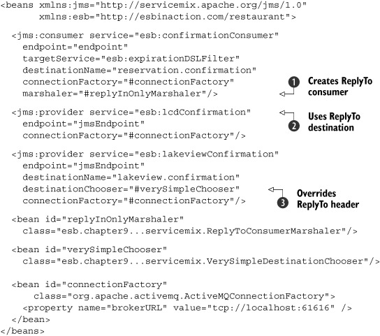
The JMS consumer that is defined uses the default In-Only message exchange pattern, but it needs to copy the JMS ReplyTo header to be able to send a response message to the LCD application. You define a custom marshaler that copies the JMS ReplyTo header value to the ServiceMix normalized message
![]() . We discussed the implementation of this marshaler in listing 9.8.
. We discussed the implementation of this marshaler in listing 9.8.
Because you use an In-Only message exchange pattern, you need to define a JMS provider endpoint to send the response message
to the LCD application. But as shown in the listing, no destination is specified for the JMS provider
![]() . Because the default SimpleDestinationChooser looks for a destination in the header of the normalized message, the message is sent to the ReplyTo destination specified by the input message sent by the LCD application.
. Because the default SimpleDestinationChooser looks for a destination in the header of the normalized message, the message is sent to the ReplyTo destination specified by the input message sent by the LCD application.
For the restaurant JMS providers, you want to implement the opposite destination-resolving functionality. Although a destination
is available in the header of the normalized message, you want the message to be sent to the destination specified with the
destinationName attribute. So you implement your own destination chooser
![]() . The implementation of VerySimpleDestinationChooser is short, as you can see in the following code snippet:
. The implementation of VerySimpleDestinationChooser is short, as you can see in the following code snippet:
public class VerySimpleDestinationChooser
    extends SimpleDestinationChooser {

  public Object chooseDestination(MessageExchange exchange,
      Object message) {
    return getDefaultDestinationName();
  }
}
You’ve now implemented all the parts of the Mule and ServiceMix table-reservation solution, and you’re ready to implement your own complex message flow in Service-Mix. You still need to do some testing and eventually a deployment before you’re finished. The great thing about testing is that you can see your integration solution working in Mule and ServiceMix.
9.5. Testing and deploying the integration solution
You’ve implemented the case study in both Mule and ServiceMix, but you didn’t yet test any part of the integration solution. In this section, we show how easily you can test an integration solution developed with Mule and ServiceMix with a JUnit test case on your development machine. After the testing phase, we discuss the deployment of the integration solution to the production environment.
9.5.1. Using JUnit to test the Mule and ServiceMix flows
JUnit is a well-known test framework for Java developers and is the industry standard to implement unit tests for Java applications. For message flows developed with Mule and ServiceMix, you need a way to unit-test the integration solution with different input messages. But to be able to unit-test a Mule or ServiceMix message flow, you need an environment where you have a Mule or ServiceMix installation, a message broker, and (if needed) a database, an FTP server, and a JEE application server. Figure 9.10 shows a developer machine environment that needs to be able to unit-test a Mule or ServiceMix integration solution.
Figure 9.10. A developer machine environment that needs to test message flows developed with Mule and ServiceMix. The Ant build files are provided as part of the source code distribution of this book.
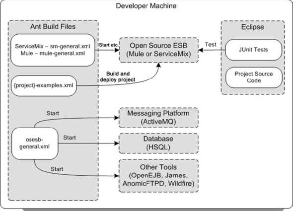
The environment shown in figure 9.10 includes a number of open source integration products. The Other Tools category includes optional products that may be needed for a message flow that uses functionality like sending email messages (James mail server) and invoking EJBs (OpenEJB). The tools shown here can be replaced with other products that provide similar functionality—instead of OpenEJB, you could use a JBoss or Geronimo application server to host the EJBs.
The minimal set of products required consists of an open source ESB and a messaging platform distribution. Note that a ServiceMix distribution contains the ActiveMQ messaging platform out of the box. To be able to test the table-reservation case study, you need a Mule and a ServiceMix distribution and also an ActiveMQ installation to provide the messaging functionality. You also need a database to persist the restaurant responses, so an HSQL installation is necessary.
To make it easier to work with the open source products in the developer machine environment, we provide a number of Ant build files with this book’s source distribution. You can use the osesb-general.xml Ant build file to start a number of integration products. For example, with the ext:start-hsqldb target, you can start the HSQL database instance.
Another Ant build file can be used to interact with the open source ESB distribution: sm-general.xml for ServiceMix and mule-general.xml for Mule. The ServiceMix JBI container provides a number of management functions that you can use with the sm-general.xml Ant build file. ServiceMix can be started and stopped, but you can, for example, also view the installed service engines and deploy a service assembly. You can use the mule-general.xml Ant build file to start and stop Mule and also to deploy a message flow project to the Mule distribution.
The third Ant build file is a project-dependent file that contains the logic needed to build and deploy the integration solution. The build logic uses the targets in the sm-general.xml and mule-general.xml build files to build and deploy the project.
Starting the development environment
Now let’s use these Ant build files to get the development environment up and running for the table-reservation solution. First, start the HSQL database with the osesb-general.xml build file by executing the ext-start-hsqldb Ant target. When the HSQL database is running, you can run the database script defined for the solution by executing the jdbc-setup-database target in the chapter9-examples.xml build file available in the Mule and the ServiceMix source distribution in the resources/chapter9 directory.
Once the database is running with the necessary tables, you can start the ActiveMQ broker by running the ext-start-activeMQ target in the osesb-general.xml build script for the Mule example. Remember that for ServiceMix, ActiveMQ is started automatically with the ServiceMix container. Because ActiveMQ is configured to create queues on the fly when needed, you don’t need to configure the queues and topic necessary for the solution beforehand.
Starting HSQL is no different from the Mule and ServiceMix implementations. But when you want to deploy the message flows to Mule and ServiceMix, you follow a different procedure. Because Mule needs to be started with the Mule configuration file and ServiceMix is hot-deployable and service assemblies can be installed when running, different steps are required when you deploy the message flow and start the ESB container.
For Mule, you first need to create the message flow jar and copy this file to the Mule distribution directory. The chapter9-examples.xml Ant build file in the resources/chapter9 directory of the Mule source distribution of this book can be executed with the default target jar to perform this first step. When the message flow jar is copied or deployed to the lib/user directory of the Mule distribution, you can start the Mule container. You do this by running the restaurant-example target in the chapter9-examples.xml file, because this target starts Mule with the Mule configuration file restaurant-config.xml. When you’ve executed all the previous steps, the Mule environment is ready for testing.
To start the ServiceMix environment, you first need to start the ServiceMix container by running the start target in the chapter9-examples.xml file in the resources/chapter9 directory of the book’s ServiceMix code distribution. When the Service-Mix container has been started, you can create and deploy the service assembly for the case study implementation. To do so, execute the deploy-restaurant target in the chapter9-examples.xml file. Now the service assembly is deployed to the ServiceMix container, and the ServiceMix environment is ready for testing.
Testing the Mule and ServiceMix case study implementations
To be able to communicate with the table-reservation message flows in Mule and ServiceMix, you should implement logic in the test case to send and receive JMS messages. Figure 9.11 shows the message exchange you should implement in the test case. The test case you need to implement simulates the TV reservation application. The test case sends, for example, a restaurant-inquiry message to the inquiries.in topic; you expect three restaurant-response messages back on the lcdtv129.response queue, which is the destination specified in the ReplyTo header of the inquiry message.
Figure 9.11. The messages that need to be sent from and received by the JUnit test case. With the JUnit test case, the reservation application is simulated.
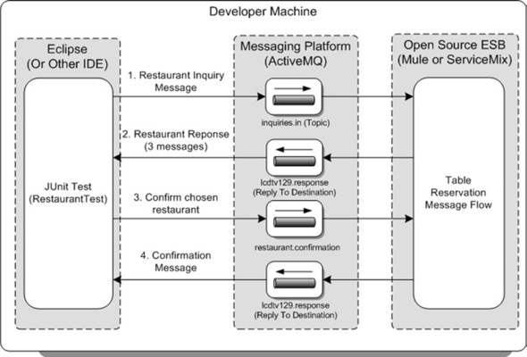
The RestaurantTest JUnit test case is pretty much the same for the Mule and ServiceMix implementations. The main difference is the format of the messages sent from and received by the test case. The ServiceMix messages are all sent in XML format, because this is the message format expected by the JBI container. The Mule messages are sent as Java objects, because this is an easy-to-use format for a Mule message flow. When you execute the RestaurantTest JUnit test case, no test errors should occur. When the test case has been executed without errors, this means that the message flow is acting as expected in different cases. The message flow is now ready for the next phase.
9.5.2. Deploying an integration solution to a production environment
You’ve fully tested the case study on your development environment, and a common next step is to test the message flow in an integration stage environment. This means the message flow is tested with all the involved applications in a real-life environment. This kind of testing is more functionally focused and is often performed by test professionals and end-user groups. Because we focus on the technical aspects of an integration solution in this book, we skip this phase and go forward with deploying the integration solution to the production environment.
In most business environments, this isn’t a task for the developer: it’s a task for the administrative department responsible for the maintenance of the integration environment. But the administrators who execute the deployment of the integration solution will need a number of artifacts from the development team. Figure 9.12 shows what the administrators need in order to deploy the case study.
Figure 9.12. An example of a production environment consisting of the open source integration products necessary for the case study. The important artifacts needed by the administrator are shown as part of the administrator machine.
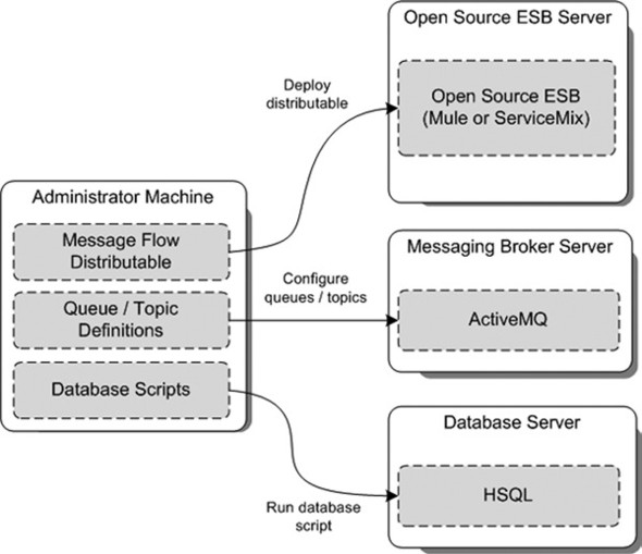
The production environment shown in figure 9.12 consists of three separate servers: the open source ESB, the messaging broker, and the database server. The actual server infrastructure depends on many aspects including the number of expected transactions and the organization’s full production environment.
The figure also shows the important artifacts that an administrator needs in order to be able to deploy the solution. This isn’t an exhaustive list of artifacts, but it gives some insight into the needs of an open source integration environment. The development team should at least provide a message flow distributable, such as a service assembly for ServiceMix or a message flow jar for Mule.
In addition to this artifact, the administrator requires an overview of the queues and topics used by the integration solution. If queues or topics don’t exist yet on the messaging infrastructure, the administrator needs to add them to the broker with the configuration parameters specified by the development team. Think of parameters like the queue name and description, and persistent or nonpersistent settings. In this case, the administrator also needs to run some database scripts to create the necessary tables in the HSQL database.
This is just a quick overview of the deployment artifacts and the administrator tasks to deploy the integration solution to a production environment. The focus of this book is on developing integration solutions with Mule and ServiceMix and not on administering the production environment.
We’ve reached the end of the case study implementation. We’ve discussed the different phases of a typical integration project from design to deployment, and we’ve introduced a pattern-based design approach. To learn more about monitoring and managing an open source ESB environment, turn the page to the next chapter.
9.6. Summary
This chapter provides you with enough guidance to enable you to be part of a full-blown integration project with open source ESBs like Mule and ServiceMix. We’ve introduced the Enterprise Integration patterns in a compact way; you can also refer to http://www.enterpriseintegrationpatterns.com. Based on these patterns, we introduced a pattern-based design approach to be used in the design phase of an integration project. This isn’t a heavyweight approach; it focuses on visualizing and describing the functionality of the integration solution in an easy way.
The case study introduced a lot of exciting integration functionality that you implemented with Mule and ServiceMix. You saw that it’s easy to implement the Publish-Subscribe pattern in both Mule and ServiceMix, and you implemented content-based routing rules in just a few lines of code. We also showed you how easily you can add persistency to a message flow by using the Spring and Hibernate frameworks.
With the knowledge you’ve gained while reading this chapter, you can now guide your team members through the phases of an integration project. What we haven’t yet discussed are the monitoring and management of integration solutions for Mule and ServiceMix. In the next chapter, you’ll learn how you can monitor the flow of messages and you’ll be introduced to some great management tools that make it easier to manage the integration environment.