
In the last two chapters, we have learned about the fundamental units of electricity—charge, current, voltage, and resistance. In this chapter, we are going to put this information to use in a real circuit.
5.1 Circuit Requirements
- 1.
A source of power which provides electricity for your circuit (this is usually a combination of both a source and destination for the electricity)
- 2.
A network of wires and components that ultimately lead from the source to the destination
- 3.
Some amount of resistance in your circuit
We need the source because, without a source of power, the charge won’t move! If we have a circuit, but no electrical power, it will just sit there. In our circuits, batteries will usually provide the power we need. They will do this by providing a (relatively) constant voltage to our circuits.
We need the wires because unless we provide a complete pathway from a higher voltage (the source) to a lower voltage (the destination), the electricity won’t be able to move. If we want the charge to move, we have to make a pathway from the higher voltage to the lower voltage. Without this pathway, we have what is known as an open circuit . No electricity flows in an open circuit.
The components in the pathway from the source to the destination do the “electrical stuff” that we want to accomplish, whether that is turning on a light, running a motor, running a computer, or whatever else it is we want to do. In order for them to take advantage of the electrical power, they have to be in the pathway in which the current is moving. Think of this like a watermill—those structures that sit near a river and use the power of the water moving through the river to turn a wheel and therefore operate whatever is inside the house. In order for that to work, the water must flow through the watermill-connected structure. If the watermill is not built next to the river or if the river runs dry, the watermill doesn’t work. Similarly, if the components are not in the flow of moving electric charge, they will not operate.
However, in addition to the wires and components, we must also have resistance (though sometimes this is added by the components themselves). Without resistance, the current would be too high. If you had zero resistance, the current would be so high that it would immediately drain your battery and likely destroy all of your components that you have connected. You can actually see this using Ohm’s law. If we have a 10-volt source with no resistance, the current is given by the equation I = V/R = 10/0 ≈ ∞. Dividing by zero gives you, essentially, infinite current. Now, wires and batteries themselves have some amount of resistance, so the current wouldn’t be infinite, but it would be very, very large and would quickly drain your battery and destroy any sensitive components you had connected. Therefore, every pathway from the positive side of the battery to the negative must have some measurable amount of resistance. When a pathway from positive to negative occurs without resistance, this is known as a short circuit.
In other words, to accomplish real tasks with electricity, we must control its flow. If it doesn’t flow (as in an open circuit), it can’t do anything. If it flows without resistance (as in a short circuit), it does damage rather than work. Therefore, the goal of electronics is to provide a controlled route for electric charge to follow so that the power of electricity does the things we want it to do on its way from the source to the destination.
If you’ve ever heard the phrase “shorting out,” that refers to the fact that if you have a short circuit, it will often run too much current through a component and break the component. Sometimes this causes sufficient damage to actually damage the connections within the circuit. So, although the original problem was that there was a short circuit (i.e., something that created a pathway which bypassed resistance in the circuit), the resulting problem is that the damage leaves you with a permanent open circuit.
Interestingly, shorting out is actually usually a better result than having a permanently short circuit, which would leave you open to your project heating up and potentially catching on fire. This is why many projects which have larger power sources often use fuses. The goal of the fuse is to break either before other parts of the circuit break or before something catches fire.
5.2 Basic Components
Batteries (9-volt)
Battery regulator
Resistors
LEDs
As we have discussed, batteries provide a relatively constant amount of voltage between the positive and negative terminals. A 9-volt battery, therefore, is supposed to have a 9-volt difference between the positive and negative terminals. However, there is an actual range that 9-volt batteries have. A 9-volt battery, depending on the battery chemistry, will deliver between 7 and 10 volts. Additionally, when the battery is worn out, its voltage will decrease as well.
Therefore, in order to make the projects operate more uniformly across different power sources, our projects will often include a regulator, which will take the battery’s voltage (which can vary from 7 to 10 volts) and return a constant 5-volt output. So keep in mind that if the project does not have a regulator attached, the actual voltages in the circuit may vary depending on the battery. If the project does have a regulator attached, it should be reliably yielding a 5-volt difference from the positive to the negative. We will treat the regulator just like a battery, but one that is more stable and reliable than a battery.
A resistor is a device that, as its name implies, adds resistance to a circuit. Resistors have colors that indicate how much resistance they add to the circuit. You don’t need to know the color codes yet, but if you are curious, you can see the resistor datasheet in Appendix E. So, if we want to add 100 Ω to our circuit, we just find a resistor with a value of 100 Ω. Resistors are not the only devices that add resistance to a circuit, but they are usually what are used when you want to add a fixed amount of resistance. Resistors have two terminals (connecting points), but they both function identically—unlike other components, there is no backward or forward for a resistor. You can put them in your circuit either way, and they will function just fine.
Of the components in this section, the LED is probably the strangest. LED stands for “light-emitting diode.” A diode is a component that only allows current to flow in one direction. It blocks the flow of electricity in the other direction. However, more importantly, LEDs emit light when current passes through them. However, LEDs do not resist current, so they must be used with a resistor to limit the amount of current flowing through them (most of them will break at 20–30 milliamps). Also, since LEDs only allow current to flow one way, they have to be wired in the correct direction. To find out which way to wire an LED, look at the legs of the LED—one is longer than the other. To allow current flow, the longer leg of the LED should be on the more positive side of the circuit.
Most of your components (especially your resistors) come with very long legs. You can feel free to bend or cut these legs however you please to better fit in your circuit. However, on LEDs (and any other component where leg length matters), be sure to keep the longer legs longer so you don’t get confused about which way it should be inserted in your circuit.
5.3 Creating Your First Circuit
One 9-volt battery
One red LED (other colors will work too)
One 1,000 Ω resistor (anything from 400 ohms to 2,000 ohms should work)
If you already have resistors, you can use a multimeter to determine the resistance, or you can use the color chart in Appendix E. Most electronics enthusiasts I know don’t actually use the color codes, because they are too small. If you have better vision than we do, then the color chart may work great. Otherwise, use a multimeter to check the resistance, or, better yet, keep your resistors organized so it is easy to find the value you want. If you don’t have resistors, it is even easier—just buy a resistor with the resistance you are looking for!
Multimeters are incredibly flexible tools, and they are pretty cheap too. For the purposes of this book, you don’t need anything fancy—the cheapest one will do just fine! Be sure that the resistor is not connected to anything else before testing.
To find the value of the resistor, look for values on the multimeter marked with the ohm sign (Ω). Set the dial to the lowest resistance value it has (remember to think about the metric suffixes from Chapter 2—for instance, 10 M means 10,000,000). Then, test the resistor by putting the two multimeter probes on the two legs of the resistor. It is okay to hold the probes on the resistor legs with your fingers. Many multimeters require you to only use the pointed tips of the probes in order to measure values accurately.
If the screen shows a 0 or 1, that means that the resistor’s value is actually too large for it to register at that setting. In that case, move the dial on the multimeter to the next setting higher and try again. If the screen shows a more precise value, then use that value plus whatever metric suffix the multimeter is set to. For instance, if the multimeter is set to 10 M, then you would add the M suffix to whatever value is shown on the screen. That is the value of the resistor.
If you did buy a fancy, expensive multimeter, it may only have one spot for measuring resistance, marked as ohm without listing any number by it. In this case, it will automatically do that same process internally and report the results to you like magic.
More information about multimeter use is found in Chapter 6.
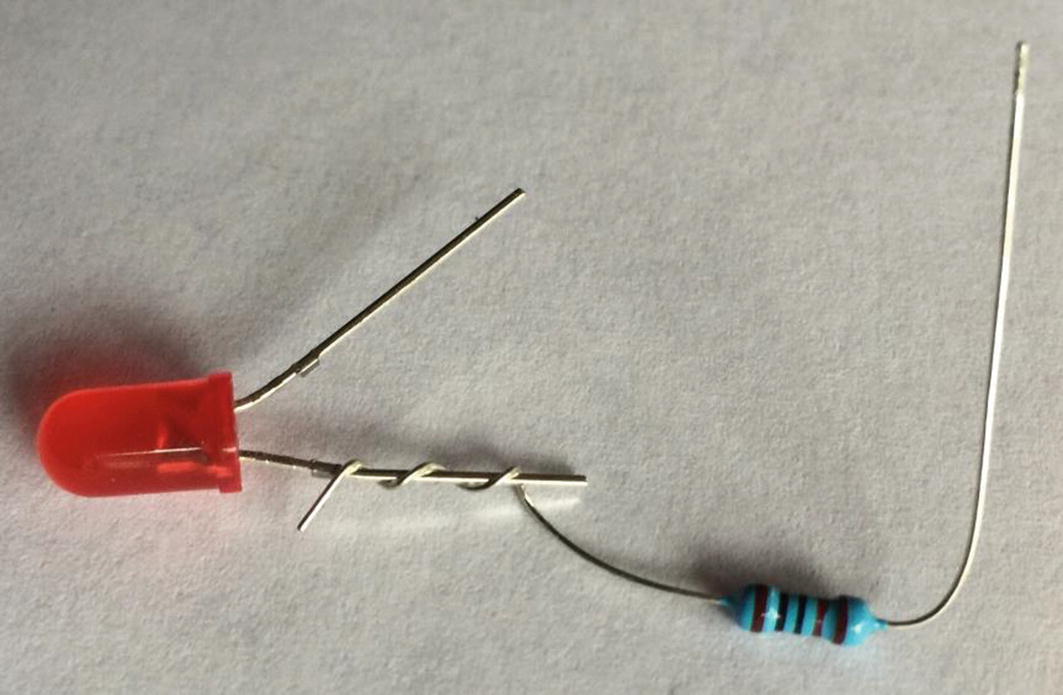
Wrapping the Resistor Around the LED’s Short Leg
Now, take the long leg of the LED and touch it to the positive terminal of the battery. Nothing happens—why not? Nothing happens because, even though we have connected the wires to the positive side of the battery, the electricity has nowhere to go to, so the current won’t move. We have an open circuit because there is not a complete path from positive to negative.
Now, touch the long leg of the LED to the battery and, at the same time, touch the unattached end of the resistor to the battery. The LED should give a nice glow of its color. Congratulations! You have built your first circuit!
Even though we can’t see the electricity moving, I hope you understand how it will flow through the circuit. We can trace the current flow from the positive terminal of the battery through the LED. The resistor limits the amount of current flowing through the circuit and therefore through our LED (the resistor can actually go on either side of the LED; it will limit the flow no matter which side it is on). Without the resistor, the battery would easily go over the 30-milliamp rating of our LED, and it would short out and no longer work. If you connected it without a resistor, you might see it turn on for a moment and then very quickly turn off, and then it would never work again. If you have an extra LED, you can try this out if you want. It is not dangerous—it will just cost you the price of an LED.
If your LED is backward, no current will flow at all. It won’t hurt the LED, but it won’t turn on unless it is oriented in the right direction.
5.4 Adding Wires
We are not going to physically add wires to our circuit at this time, but I did want to make a note on wires. Changing the lengths of wires will not affect our circuits in any way. On advanced projects (usually projects with extremely high precision or extremely long wires), the length of a wire will sometimes have an effect on such circuits. We are not doing any high-precision circuits, and our wire lengths are all less than a meter. Therefore, for the electronics we are doing, we can totally ignore wire length.
Therefore, if we connected our components using wires rather than directly wrapping their legs around each other directly, it would have no effect on the circuit at all. What is important is not the wires but the connections—what components are connected together and how are they connected. The length of the wire used to connect them is not important. You can connect them with a really long wire or directly touch the legs of each component together with no wires. It doesn’t matter because the result is the same—the components are connected.
5.5 Drawing Circuits
So far, we have only described circuits in words or by showing you pictures. This, however, is a lousy way of describing circuits. In complicated circuits, trying to trace the wires in a photograph is difficult. If you wanted to draw a circuit that you wanted built, you would have to be an artist to render it correctly. Likewise, reading through text describing a circuit takes a long time, and it is easy to get lost when discussing large circuits.

Basic Component Diagram Symbols
Then, the components are connected together using lines to represent the wires and connections between the components.

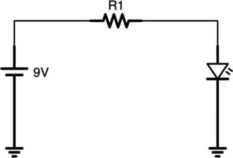
Basic LED Circuit Drawn as a Diagram
Notice that our components are laid out on the diagram with wires connecting them. Remember that it doesn’t matter if we have very long wires or very short wires or if the components are directly placed end to end—the resulting circuits will operate identically. Also notice that each component is labeled (R1 and D1) because, as we make more complicated circuits, it is important to be able to refer back to them.
It does not matter in a diagram which way you have your components turned, how long or short your wires are, or what the general spacing looks like. When you actually wire it, all of those things will change. The important part of a circuit diagram is to convey to the reader what the parts are, how they are connected, and what the circuit does in the way that is easiest to read.

Alternative Ways of Drawing the Basic LED Circuit
For consistency, I like to draw all of my batteries to the left of the drawing with the positive side on top. By keeping the battery positive-side-up, components with higher voltage are usually closer to the top, and components with lower voltages are usually closer to the bottom, with the ground (i.e., 0 volt) coming back into the negative terminal. I also try to make my wire lines as simple as possible in order to make following them easier.
By keeping some amount of consistency, it is easier to look at a drawing and see what is happening.
5.6 Drawing the Ground
Remember that for electricity to move, every circuit must be fully connected from the positive side to the negative side. That means that in larger circuits, there are numerous connections that come from the positive or go back to the ground/negative. Because of this, a special symbol has been adopted to refer to the ground point in a circuit. This symbol, the ground symbol, has three lines, each shorter than the next. Points on a circuit that have this symbol connected to them are connected to each other (usually they are all connected to the negative side of the battery).
Basic LED Circuit Drawing Using the Ground Symbol
This doesn’t help us a lot for this circuit (and, in fact, it makes it a little less easy to read). However, in complex circuits, it is much easier to write the ground symbol than trying to have 20 lines drawn back to the negative terminal.
Additionally, the same is true with the positive side of the battery. Many components require a direct connection to a specific voltage to work correctly. These are usually marked with just a disconnected wire with the end of the wire marking what voltage it requires. We make less use of that symbol in this book than the ground symbol, but it does come in handy sometimes.

Simple LED Circuit Using Positive and Ground Symbols
5.7 Review
- 1.
Every circuit requires a source of power (usually a battery), wires and components, some amount of resistance, and a complete path back to the negative side of the power source.
- 2.
An open circuit is one that does not connect back to the negative side (and thus does not provide any electricity), and a short circuit is one that connects back to the negative side without any resistance (and thus overwhelms the circuit with current).
- 3.
A battery supplies a fixed voltage between its two terminals.
- 4.
A resistor provides a fixed resistance (measured in ohms) within your circuit.
- 5.
An LED allows current to flow in only one direction, gives off light when current is flowing, but is destroyed when the current goes above 20–30 milliamps.
- 6.
The longer leg of the LED should be on the positive side of the circuit.
- 7.
Wires on simple circuits can be almost any length (from zero to a few meters) without changing the functionality of the circuit.
- 8.
A circuit diagram is a way of drawing a circuit so that it is easy to read and understand what the circuit is doing.
- 9.
Each component has its own symbol in a circuit diagram.
- 10.
Components labeled with the ground symbol are connected together, usually at the negative side of the battery.
- 11.
Voltage sources can be similarly labeled by a wire connected on one side labeled with the voltage that it is supposed to be carrying.
5.8 Apply What You Have Learned
- 1.
Calculate the amount of current running in the circuit you built in this chapter using Ohm’s law. Since Ohm’s law gives the results in amps, convert the value to milliamps.
- 2.
Let’s say that the minimum amount of current needed for the LED to be visibly on is 1 milliamp. What value of the resistor would produce this current?
- 3.
Let’s say that the maximum amount of current the LED can handle is 30 milliamps. What value of the resistor would produce this current?
- 4.
Draw a circuit diagram of a short circuit.
- 5.
Take the circuit drawing in this chapter, and modify it so that it is an open circuit.
- 6.
Draw a circuit with just a battery and a resistor. Make up values for both the battery and the resistor and calculate the amount of current flowing through.