
Basic Concepts and Control Architecture of Microgrids
This chapter discusses the basic concepts and control structures of microgrids. Nowadays, distributed generation technology is becoming increasingly mature, and is deployed as active distribution networks working cooperatively with conventional power grids. In addition, the issues of exhaustible natural resources, fluctuating fossil fuel prices and the security of electricity have encouraged governments around the world to hold positive attitudes toward the development of emerging microgrids. Future microgrids will allow high renewable penetration and become building blocks of smart grids thanks to advanced communication and information technology. As the underlying scientific and engineering research questions are being answered, there is no doubt that microgrids will play an extremely important role in future electric power and energy systems.
Keywords
Centralized control; Control architectures; Decentralized control; Energy storage system; Microgrid concepts; Microgrid protection; Renewable energy resources; State estimation
1.1 Introduction
This chapter discusses the basic concepts and control structures of microgrids. Nowadays, distributed generation technology is becoming more and more mature, and is deployed as key elements of active distribution network working cooperatively with conventional power grids. In addition, the issues of exhaustible natural resources, fluctuating fossil fuel prices and security of electricity have encouraged governments around the world to hold positive attitudes toward the development of emerging microgrids. Future microgrids will allow high renewable penetration and become building blocks of smart grids thanks to advanced communication and information technology. As the underlying scientific and engineering research questions are being answered, there is no doubt that microgrids will play an extremely important role in future electric power and energy systems.
1.1.1 Concepts of Microgrids
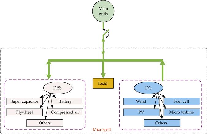
Power generation in the traditional power grid is highly centralized, with power and energy flowing unidirectionally from large synchronous generators through a transmission/distribution network to end-users. However, the technological issues associated with traditional electric utilities, as well as the environmental problems caused by the combustion of fossil fuels, have stimulated research and development into new power system technologies. With the emergence of distributed energy resource (DER) units, e.g., wind, photovoltaic (PV), battery, biomass, micro-turbine, fuel cell, etc., microgrid technologies have attracted increasing attention as an effective means of integrating such DER units into power systems. However, there is no clear definition of a microgrid, and the concept varies in different countries and regions. Based on the European Technology Platform of Smart Grids [1], a microgrid is a platform that facilitates the integration of distributed generators (DG), energy storage systems (ESS) and loads to ensure that the power grid can supply sustainable, price-competitive and reliable electricity. Figure 1.1 shows a typical microgrid structure, comprising DGs, such as combined heat and power unit (CHP), microturbines, PV systems, wind power systems, fuel cells; a distributed energy storage (DES) facility such as battery banks, super-capacitors, flywheels, electric vehicles; flexible loads and control devices.
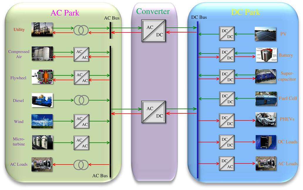
Microgrids can be classified as AC and DC types. AC microgrids can be integrated into existing AC power grid, but they require quite complicated control strategies for the synchronization process in order to preserve the stability of the system. On the other hand, DC microgrids have better short circuit protection and significantly improved efficiency. Furthermore, some synchronous units (e.g., diesel generators) and some non-synchronous units (e.g., micro-turbine machines) are usually connected in the same microgrid system. As the penetration level of more DC loads (especially Plug-in Hybrid Electric Vehicles) increases, hybrid AC/DC synchronous/non-synchronous microgrids via multiple bi-directional converters will become increasingly attractive. Figure 1.2 shows a typical system structure for a hybrid AC/DC microgrid that contains power electronic interfaces and multiple DER units.
Although many types of DG units are more sustainable, a high level penetration of renewable energy resources (e.g., wind, PV) in microgrids can make maintaining grid stability and delivering reliable power challenging due to intermittency and fluctuation issues. In such cases, a DES can play an essential role in improving stability, strengthening reliability, and ensuring security. Not only can DES units be used for smoothing the fluctuations from the output of DG units, but they can also contribute to the stable operation of microgrids. Advances in material science and power electronics technologies have facilitated the effective employment of new DES facilities.
The development of microgrids will bring many benefits but does present significant challenges. For instance, the voltage and frequency disturbance problems in unpredictable weather conditions when integrating renewable energy, monitoring and managing local power generation and loads, designing protection devices to cope with bi-directional power flow and so on. More research needs to be conducted to solve these problems.
1.1.2 Benefits of Microgrids
As mentioned, microgrids provide an effective way for integrating small-scale DERs in proximity of load into low-voltage distribution network. Microgrids can supply highly reliable power to a wide range of customers, both residential and commercial, such as schools, hospitals, warehouses, shopping centers, university campuses, military installations, data centers, etc. Various research stations (Arctic-based or space-based) can also utilize this technology to enhance their operation since it will provide an uninterrupted power supply. It is also useful for remote places having no or limited access to the utility grid. Further, it is beneficial for customers facing large power outages (for example, hurricane-prone areas). Microgrid technology can also be used in areas facing high stress and congestion in their transmission and distribution systems (for example, the northeastern US).
There are many benefits of implementing microgrids. They help facilitate the integration of distributed generation, most notably, renewable energy resources such as wind and solar. This helps curb the dependency on fossil fuels as a source for electricity, significantly reducing carbon emissions and pollution, and thus promotes energy sustainability. They also facilitate the use of highly efficient generators which utilize combined heat and power technology. They can increase the quality of power at the consumer side. With proper control, microgrids increase electrical reliability by decreasing outage occurrences as well as their duration. Utilities see microgrids as controllable loads, which can contribute to peak shaving during times of peak demand by reducing their own consumption via shedding of non-critical loads and delivering more power to the main grid utility. Microgrids can lower overall distribution system losses by implementing distributed generation located at the demand site eliminating the need for transmission lines and deferring the construction of new transmission lines to a later time. This also results in higher energy efficiency. By using renewable energy resources like wind and solar fuel costs can be reduced. There are also several economic opportunities for microgrids if they can participate in local electricity markets. They can offer several ancillary services to the main grid if properly incentivized to do so. Microgrids can provide active power support via frequency regulation, black start support, system restoration support, and load balancing services. Microgrids can be compensated for these services via fixed payments, payments for service availability, payments based on frequency of usage, and/or payments based on lost opportunity cost. This last is the revenue that the microgrid could have made but was not able to because it had to be available for the main utility grid even if it was not called upon [2].
1.1.3 Integration of Microgrid to Distribution Networks
Conventional DGs are usually directly interconnected to distribution networks at medium or high voltage levels. However, generators in microgrids (e.g., PV, wind turbines, fuel cells) have a relatively small installed capacity (e.g., a few hundred kWs). These generators should be connected to distribution networks at a low voltage level. In conventional power systems, loads are passive and power only flows from distribution substations to customers, but not in the opposite way. But power can flow in both directions between microgrids and the main grid.
In the US, the Federal Energy Regulatory Commission (FERC) provides oversight for constructing electric generation, transmission or distribution facilities. FERC permits various ways of integrating renewable energy resources to facilitate electricity market reform.
The technical requirements for distribution interconnections have been stipulated in IEEE 1547 “IEEE Standard for Interconnecting Distributed Resources with Electric Power Systems”. IEEE 1547 is suitable for all distributed resource technologies, with aggregate capacity of 10 MVA or less at the Point of Common Coupling (PCC).
1.1.4 Basic Components and Operation Strategies in Microgrids
The controllable components in a microgrid include renewable sources, dispatchable sources, ESS and demand side management. All of them work together to maximize the total microgrid profit.
The load control scheme in microgrid can either run in non-automated or automated mode. In non-automated mode, customers can obtain the electricity price and choose whether to switch on or off the loads via remote controls. In automated mode, on-off control is realized by loads themselves through pre-programming or receiving control signals.
The objectives of operating a microgrid depends on the stakeholders’ interest. These stakeholders could be microgrid operators, distributed generation owners, distributed generation operators, consumers, etc. To maximize the economic profit, the objective is to minimize total microgrid costs, taking into consideration the impact of the microgrid on the main power grid and the environment. To maximize the technical profit, the objective is to minimize the total power losses and voltage fluctuations, and this option has been adopted by majority of system operators. To maximize the environmental benefits, the objective is to minimize the emissions from the DG in order to meet environmental requirements. The final goal is to combine all the above economic, technical and environment factors to achieve maximum comprehensive benefits [3].
1.1.5 Microgrid Market Models
The microgrid market model consists of consumers, distributed generation owners, the market regulator, retail suppliers, energy service companies (ESCO), distribution system operators (DSO) and microgrid operators. The motivation for using microgrids can be analyzed from either the distributed generation side or the demand side.
On the distributed generation side, since most governments around the world encourage the development of sustainable and clean energy, there are no strict rules for controlling the amount of power output of renewable energy system units. The distribution system operator is responsible for accepting all the electricity from the microgrid if its integration does not impact the safe operation of the grid [3].
On the demand side, the demand response can be classified by the way that the load changes. The first demand response is price-based and the second is incentive-based. In the first situation, the demand response is based on the real-time pricing, critical-peak pricing and ToU (Time of Use) rates. In the second situation, the program operator can switch on or off the customers’ loads remotely without considering whether the electricity price is fixed or changing. The purpose of employing these two demand response strategies is to reduce the difference between the load peak and the load valley.
In addition to this, microgrid also provides ancillary services based on the specific requirement of transmission or DSO. The goal is to maintain system stability as well as improving its power quality. Ancillary services can also be divided into two categories according to the operation modes of microgrids:
1.2 Microgrid Control Issues
The most important feature that distinguishes a microgrid from a conventional distribution system is its controllability, the purpose of which is to make microgrids behave as a controllable, coordinated module when connected to the upstream network.
1.2.1 Introduction
The function of microgrid control can be divided into three parts; the upstream network interface, microgrid control and protection, local control [3].
The upstream network interface decides whether the microgrid is able to operate in grid-connected mode or islanded mode. It makes decisions for market participation and coordination with the upstream network. The microgrid control includes voltage and frequency regulation, real and reactive power control, load forecasting and scheduling, microgrid monitoring, protection and black start. Local control and protection level encompasses primary voltage and frequency regulation, primary real and reactive power control for each local generation and energy storage unit.
To a large extent, the control of microgrids relies on information and communication technology (ICT). Therefore, it is necessary to discuss frequently-used technologies applied in distribution networks. The first of these are microprocessors, which are widely used in microgrids since they can provide support to make more complicated inverters and load controllers. With the rapid development of integrated circuit technology, future microprocessors are likely to become smaller, faster, cheaper and equipped with the ability to communicate. The second technology is communication. Communication networks offer adequate bandwidth to the users. In addition, the remote control of microgrids is highly reliant on good communication. The other two technologies are service oriented architectures (SOA) and the internet of energy. The former ensures the normal operation of microgrids in multiple layers and the latter uses software to remotely control home appliances through an internet gateway.
1.2.2 Centralized Control Versus Decentralized Control
Microgrids can either operate in centralized control mode or decentralized control mode [3]. In centralized mode, the Microgrid Central Controller (MGCC) plays the most important role in optimizing a microgrid. Based on electricity price, gas price and security information, the MGCC decides how much power is needed to be imported from the utility network and how many non-critical loads should be shed in critical conditions. In decentralized mode, the primary goal is to maximize power production to meet the load demands and export excess electricity to utility grid.
1.2.3 Forecasting
The implementation of both centralized control and decentralized control strategies requires load forecasting, actual renewable resources power output estimation and information about electricity prices. Forecasting load and renewable generation requires data collection and a weather forecast, which may increase the operation cost [4,5]. Therefore, the benefit of forecasting should be greater than the extra cost involved. Currently, forecasting is mainly focused on electricity price, load demand and PV generation aspects for large interconnected systems. A number of forecasting methods are available and implemented in utility operation. The simplest forecasting method (persistent method) is to predict a variable based on its current value.
1.2.4 State Estimation
In addition to forecasting, state estimation is another issue associated with microgrid control. Due to redundant measurements, state estimation at the transmission level can reduce the uncertainty. But at distribution level, decisions need to be made without the support of sufficient data at middle-voltage level or low voltage level. Therefore, the undetermined parameters of the model need to be estimated.
The estimation problem consists of a parameter estimation principle and a parameter estimation algorithm. The common principles used are least squares, maximum likelihood, minimum variance, minimum risk, etc. The algorithms used can be divided into iterative and recursive algorithms. The iterative algorithms include Newton’s method, gradient method and Gaussian method, whereas the recursive algorithms include real-time online estimation, point-by-point data processing and parameter updating [6].
1.2.4.1 Least Squares Estimation
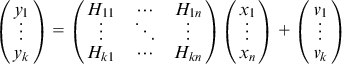
Suppose there is a set of unknown parameters, ![]() . The aim is to estimate the value of x with some measurements containing noise,
. The aim is to estimate the value of x with some measurements containing noise, ![]() . To find the best estimate, the simplest case can be considered in which each
. To find the best estimate, the simplest case can be considered in which each ![]() is a linear function of
is a linear function of ![]() , with some measurement noise
, with some measurement noise ![]() . Thus:
. Thus:
(1.1)
where ![]() , and
, and ![]() is a
is a ![]() matrix. So Eq. (1.2) can be obtained as follows:
matrix. So Eq. (1.2) can be obtained as follows:
(1.2)
 (1.2)
(1.2)
Given an estimate ![]() , the difference between the noisy measurements and the expected values is:
, the difference between the noisy measurements and the expected values is:
(1.3)
Using the least squares principle, we will try to find the value of ![]() that minimizes the cost function:
that minimizes the cost function:
(1.4)
The necessary condition for the minimization is that the partial derivative (gradient) of ![]() with respect to
with respect to ![]() equals zero.
equals zero.
(1.5)
Then we get:
(1.6)
The inverse ![]() exists if
exists if ![]() and
and ![]() is non-singular [7].
is non-singular [7].
1.2.4.2 Weighted Least Squares Estimation
Suppose that confidence is not equal on all measurements. For example, some of parameters are measured with low noise, while others are measured with high noise. The other factors are the same as those described in Section 1.2.4.1, so the process can also start with function (1.1). Assume that each measurement may be taken under different conditions so that the variance of the measurement noise may be distinct too:
(1.7)
Assume that the noise for each measurement has zero mean and is independent [8]. The covariance matrix for all measurement noise is:
(1.8)
 (1.8)
(1.8)
The sum of squared differences weighted over the variance of the measurements can be minimized.
(1.9)
Equation (1.9) can be expanded as:
(1.10)
Therefore, the final estimation result is:
(1.11)
1.2.4.3 Newton-Raphson Algorithm
The Newton-Raphson algorithm is used to find the roots of a system of equations [9,10]. Assume there is an equation to be solved as follows:
(1.12)
Solving this requires two steps: (i) Select an initial value ![]() which is close to the zero point; (ii) draw a tangent line through the point
which is close to the zero point; (ii) draw a tangent line through the point ![]() and calculate the intersection point between the tangent line and x-axis. This point can be called
and calculate the intersection point between the tangent line and x-axis. This point can be called ![]() .
.
(1.13)
![]() should be closer to the zero point than
should be closer to the zero point than ![]() . Finally, after n iterations, the roots can be obtained.
. Finally, after n iterations, the roots can be obtained.
(1.14)
When solving a system of nonlinear equations, the principle is the same. Assume there is a system of equations:
(1.15)
The system of equations has m equations and m unknown variables. So the equation can also be written as another form:
(1.16)
 (1.16)
The roots of the system of equations are computed as follows:
(1.17)
(1.18)
(1.19)
(1.20)
 (1.20)
1.3 Microgrid Control Methods
In a microgrid, different kinds of control methods are applied to ensure reliable operation, in both grid-connected mode and islanded mode. Depending on the DG and operating conditions, there are three main types of control methods: PQ control, V/f control and droop control.
1.3.1 PQ Control
The main objective of PQ control is to keep the microsource’s active power and reactive power constant when the frequency and voltage deviation stay within prescribed limits. In PQ control, the active and reactive power are firstly decoupled in order to achieve independent control. The active power controller aims to maintain the active power output constant at a given reference value within the permissible frequency range. The reactive power controller aims to maintain the reactive power output constant at the given reference value within the permissible voltage range. However, this PQ control method cannot maintain the frequency and voltage constant, so an extra distributed generator is needed to regulate the voltage and frequency of the microgrid within the acceptable range. If microgrid operates in the grid-connected mode, the main power grid is responsible for maintaining the voltage and frequency of the microgrid.
1.3.2 V/f Control
The main objective of V/f control is to maintain the system frequency and voltage magnitude constant regardless of the actual active and reactive power outputs of microsource. A frequency controller adjusts the active power output to maintain the frequency at the given reference value. A voltage controller adjusts the reactive power output to maintain the voltage at the given reference value. V/f control is common when the microgrid operates in islanded mode.
1.3.3 Droop Control
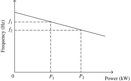
1.3.3.1 Active Power Control
In a microgrid, the load keeps changing all the time, so the generators will change their power output based on the frequency deviation. The relationship between active power output and frequency can be described by the following equation and Figure 1.3.
(1.21)
where ΔP=power output change of the generator; Sp=reciprocal of slope of curve, kW/Hz or MW/Hz, which is determined by characteristic of each DG.
1.3.3.2 Voltage Control
The linear relationship between reactive power and terminal voltage, as shown in Figure 1.4, is similar to that of active power and frequency. The system voltage control can be carried out by adjusting the reactive power output of microsources.

1.4 Control Architectures in Microgrids
Compared with a conventional power grid, microgrid has two different modes, grid-connected mode and islanded mode (grid-disconnected) mode. The microgrid should be able to operate reliably in both modes. Depending on the roles of distributed generation in the microgrid, the control architectures can be either master-slave control, peer-to-peer control or hierarchical control.
1.4.1 Master-Slave Control
Master-slave control structure is illustrated in Figure 1.5. When a microgrid operates in islanded mode, either the DG or ESS of the master unit will take V/f control role to provide voltage and frequency references for other DGs and ESS within the microgrid. Meanwhile, other DGs are in PQ control mode. The controller with V/f control method is named the master controller while the other controllers are slave controllers. Slave controllers take corresponding actions based on those of the master controller. However, microgrid operates in grid-connected mode in most situations. In such cases, the main grid provides voltage and frequency references for microgrid, so all the controllers within microgrid are in PQ control mode. If a fault occurs on the main grid side, the microgrid can seamlessly transfer from interconnected to islanded mode. One of DG’s controls (master unit) needs to switch to V/f control mode.
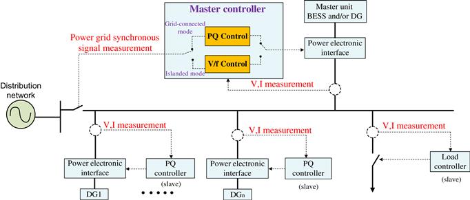
The commonly-used master units can be divided into three categories: ESS, DG and ESS integrated with DG. If ESS is used as the master controller, the microgrid cannot operate in islanded mode for very long since ESS keeps discharging and will eventually run out of power. If a DG like a micro-turbine is used as the master controller, the voltage and frequency can be regulated easily, so the microgrid can operate in islanded mode for a long time. Another method is to use both DG and ESS as master controllers. This method works for renewable generators (PV, wind turbine, etc.). Due to the intermittency and stochastic nature of renewable generation outputs, ESS can help reduce the voltage and frequency fluctuation so that the microgrid is able to run in islanded mode for a long time.
If the energy capacity of the ESS is large enough, it can act as a master unit (V/f mode) to offer the specified voltage and frequency support for the islanded microgrid and adjust the power output to bring the frequency and voltage back to the scheduled values. In contrast, other DGs still remain as slave units operating in constant power (PQ) mode [11–13]. The ESS is required to mitigate the dynamic mismatch between load and renewable power generation in the islanded microgrid. However, it should be noted that the ESS cannot maintain at discharging state for a long time due to the State of Charge (SOC) limit, so islanded operation with only ESS as a master unit can only be sustained for a relatively short period of time.
If the energy capacity of ESS is small and limited, it can be integrated into the DC-link of a certain renewable power source as a combined master unit (V/f control mode) to provide the desired voltage and frequency support for an islanded microgrid [14]. Under these circumstances, a coordinated V/f and P/Q control strategy is required to realize the frequency regulation of the islanded microgrid [15]. Provided that the renewable power output from the PV or wind turbine generator (WTG) is larger than active power demanded for the frequency regulation of islanded microgrid and meanwhile state of charge (SOC) of battery ESS (BESS) is lower than upper limit (e.g., 80%), the battery will be charged to maintain the power balance between the generation and load to ensure frequency stability of the islanded microgrid. If the same situation occurs but SOC is higher than 80%, the battery cannot be charged due to this upper limit. In this situation, a central microgrid controller acts to smoothly change the operating state of this renewable power generator from V/f control mode to constant PQ mode, since BESS fails to assist in maintaining the desired power outputs for V/f control. At the same time, one DG with steady and sustained output (e.g., a micro-turbine generator) can operate in V/f mode. Similarly, when the renewable power output is smaller than the active power demanded for the frequency regulation of the islanded microgrid and also the SOC of BESS is higher than lower limit (e.g., 20%), the battery will be discharged to maintain the microgrid frequency. If the same scenario happens but SOC is less than 20%, the battery is unable to be discharged for frequency regulation and renewable power generator operation is switched to constant PQ mode. In this case, the V/f regulation task will be undertaken seamlessly by another DG featured with steady and sustained output in the microgrid. Using this method, the advantages of renewable energy sources can be fully utilized together with the rapid power response of the BESS so as to achieve sustained and steady islanded operation of the microgrid, in which frequency stability can be achieved. Compared with the application of ESS with large capacity, this control mode not only can minimize the demand on the ESS capacity, but also improve the overall operationing economics of the microgrid [16].
However, this control method has some disadvantages. First of all, it needs many communication channels between different controllers, which will increase the total investment cost of the microgrid. Secondly, it is difficult to apply the master-slave control method to larger systems. Lastly, implementation of the master-slave control method has strict requirements for communication and supervisory control.
1.4.2 Peer-to-peer Control
For peer-to-peer control of an islanded microgrid, all the DGs and ESS units are equal with no master-slave relation involved, as shown in Figure 1.6. Using the droop control method, designated DGs and ESS units are capable of adjusting their power outputs based on the locally measured voltage and frequency [17–18]. Any large change in load can be actively shared among selected DGs and ESS units based on individual droop coefficients so that power balance between generation and consumption is re-established in islanded operation. In a similar manner to the frequency droop control of a traditional synchronous generator, this peer-to-peer control belongs to error frequency regulation in that it allows some frequency and voltage deviation from the desired values. Compared with master-slave control, peer-to-peer control enables each DG and ESS to automatically participate in the power output allocation, which facilitates the plug and play function of DG [19]. Besides, the expense on communication system can be avoided so the system total cost is reduced accordingly. Meanwhile, there is no change in droop control strategy for DGs and BESS regardless of microgrid operation mode, so seamless switching between grid-connected and islanded mode can be easily achieved. In the practical microgrid application with the peer-to-peer control strategy used, some DGs can still adopt PQ control to realize the Maximum Power Point Tracking (MPPT) and unity power factor operation. Meanwhile, other DGs and ESS units rely on droop controls to undertake the power sharing task, which is otherwise fulfilled by the master unit in master-slave control. Through proper setting of the droop coefficients, the net power change can be shared among different DGs in order to achieve dynamic power balancing and maintain voltage and frequency within the acceptable range in islanded mode.
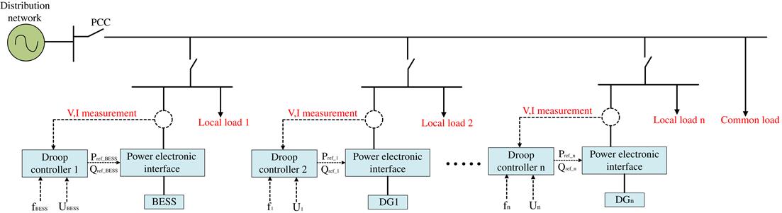
The control method used is droop control, as mentioned in Section 1.3.3. If frequency is decreased, the DG will increase its actual power output to maintain the frequency within acceptable limits. Otherwise, the active power output will be decreased. The same principle can be applied in the peer-to-peer voltage control of microgrids. If the voltage level drops, reactive power output will be increased accordingly. This process is described in Eq. (1.22).
(1.22)
Finally, the whole system will operate at a new frequency and voltage.
If peer-to-peer control method is compared with the master-slave control method, it can be seen that the controllers in peer-to-peer control architectures can make decisions using local information, which means that this architecture can save a lot of money during establishing communication system and also minimize the system complexity. Another advantage is that these architectures can fulfill the requirements for seamless transition between grid-connected and grid-disconnected modes.
Currently, it is easy to apply peer-to-peer control method in a plug and play network, but it is still not widely implemented in practical application of microgrids.
1.4.3 Hierarchy Control
In hierarchical control, a central controller is implemented to send control signals to each DG, ESS unit and controllable loads. One type of two-layer control structure is illustrated in Figure 1.7 [20]. The first objective of the central controller is to predict the load demand and renewable power generation, so a set of operation plans is developed accordingly. Based on the collected status information including voltage, current and power, this operation plan can be updated in real-time to adjust the power output and determine the start and stop of DGs, loads and ESS units. In this way, the stability of voltage and frequency is ensured and relevant protection function is provided for the islanded microgrid as well. Regarding this hierarchical control scheme, physical communication channels are required for mutual communication between DGs and top-level controller. If one channel fails to work, the entire microgrid fails to operate normally.

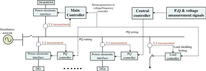
In another type of hierarchical two-layer control structure, shown in Figure 1.8, only weak communication is needed to coordinate the central controller with local controllers of DGs [21]. Using this method, transient power demand-supply balance can be achieved by the low-level controllers of DGs, and meanwhile the top-level central controllers are capable of modifying the steady-state operating points of low-level DGs and managing the load based on the variation in both DG outputs and load demands. Even if communication fails for a short while, microgrid can still maintain normal operation during the period of fault.
A type of three-layer control structure is shown in Figure 1.9 [22]. The top-level operation and management system of the distribution grid (OMDG) is responsible for monitoring the real-time operation status of the microgrid group, which consists of multiple microgrids. The system manages and dispatches these microgrids in accordance with a power market mechanism and the dispatching command from OMDG. The middle-level MGCC is in charge of monitoring the operation status such as the key node’s voltage and frequency of each microgrid in the islanded mode, power flow through each branch, current output and power reserve margins of each DG and ESS, load condition and so on. In addition, the MGCC can optimize the economic operation of each individual microgrid and provide ancillary services through the proper regulation of the ESS and DGs, including load following, operational reserve as well as frequency regulation and voltage control [14]. The bottom-level local controller consists of microsource controllers (MC) for the DG and the ESS as well as the load controller (LC), aiming to ensure a transient power balance, power quality improvement for sensitive load and dynamic load management. The complete hierarchical control strategy can be realized through the multi-agent system (MAS), which comprises main-grid agents, microgrid agents and microsource agents [23,24]. Compared with the two types of control strategy described earlier in this section, a hierarchical control-based multi-agent method can enable a microgrid group to operate in an efficient, accurate and flexible manner. Not only can frequency regulation and voltage stability be achieved through the local controller and the MGCC, but also optimized economic operation with multiple objectives as well as coordinated control between microgrid and main grid can be realized.

From the discussion in this section, it can be concluded that stable microgrid operation cannot be achieved without intelligent control strategies. Choosing and designing the suitable control strategies is essential to achieve a safe and reliable microgrid operation.
1.5 Microgrid Protection
A microgrid protection scheme differs from that of conventional low-voltage or medium-voltage distribution network. It is still a main technical problem that needs to be tackled. The protection strategy needs to take into account faults in the main power grid and also faults inside the microgrid. If a fault occurs in the utility grid, protection devices in microgrid will trip as soon as possible to cut off the interconnection between the microgrid and its upstream grid to protect the loads within the microgrid. A commonly-used method is to combine circuit breakers with directional over-current relays or electronic static switches. If a fault occurs within the microgrid, protection devices will isolate the smallest possible area of distribution feeder to separate out the fault.
Conventional protection strategies use the magnitude and direction of the fault current to determine that a fault is occurring. Protection strategies should be reliable, secure, redundant and cost-effective. However, the inverter-interfaced DERs make system protection complex. In general, the principle associated with microgrid protection can be described as “3S”: selectivity (whether to trip or not), sensitivity (whether a fault can be detected) and speed (the time for trip).
Several control and protection methods regarding microgrid are discussed in [25–28]. Some of the challenges of microgrid protection are:
1. Decide whether to connect or disconnect its upstream grid according to the magnitude of bi-directional short-circuit current.
2. Circuit breaker false trip due to the integration of DERs.
3. Contradictions between microgrid feeder protection and fault-ride-through requirement set by utility companies.
Unexpected relay tripping issues can be addressed by using adaptive protection, namely over-current protection relays combined with identification of current direction [29]. The definition of adaptive protection is “an online activity that modifies the preferred protective response to a change in system conditions or requirements in a timely manner by means of externally generated signals or control action” [30].
The design of modern adaptive protection schemes for microgrids can be divided into two types, namely pre-calculated setting group and real-time calculated setting group. Adaptive protection can also be classified as centralized or decentralized depending on control methods.
For an adaptive protection scheme with pre-calculated settings, the MGCC exchanges information with each circuit breaker and directional over-current relay through the RS-485 serial communication bus. When a fault happens, every relay makes its own decision by checking if the measurement value meets the pre-calculated tripping condition.
An adaptive protection scheme with real-time calculated settings is applied as a multifunctional intelligent digital relay (MIDR), whose structure is much more complicated than that of the adaptive protection scheme with pre-calculated settings. In general, the MIDR produces selective tripping signals and sends them to corresponding circuit breakers if a fault occurs. MIDRs can monitor both analog and digital signals.
Choosing the proper protection strategy is very important for maintaining the normal operation of a microgrid. The major problems of microgrid protection lie in variable operation conditions when renewable resources are integrated, lower sensitivity of fault current due to power electronic devices (like inverters) and false tripping. The solution to these problems is to apply an adaptive protection scheme that changes the protection settings automatically based on the configuration of microgrid. There is still great potential for development in this area. With more and more advanced protection devices developed and new relevant communication technologies applied, microgrids will become more reliable and popular in future power grids.
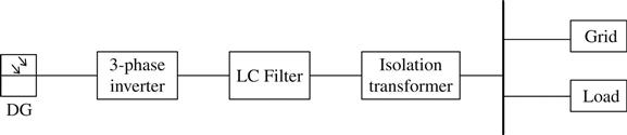
1.6 Three-Phase Circuit for Grid-Connected DG
The structure of a three-phase grid-connected DG system is shown in Figure 1.10; the system is composed of four parts: a DG, a three-phase inverter, an LC filter and an isolation transformer. Via the three-phase inverter and LC filter, the DG can generate AC power that meets the requirements of grid integration. Some of the power output is used to supply the loads and the remainder is delivered to the main grid at PCC via isolation transformer.
1.6.1 LC Filter
The harmonics from inverters are mainly made up of the carrier frequency and its integer multiples. In order to avoid the resonance effect and make the filter output close to ideal sinusoidal waveform, the cutoff frequency of LC filter must be far lower than the frequency of the lowest-order harmonic of the pulse width modulation (PWM), and at the same time much greater than the fundamental frequency. So the cutoff frequency ![]() can be chosen by using the formula in Eq. (1.23):
can be chosen by using the formula in Eq. (1.23):
(1.23)
In Eq. (1.23), ![]() is the fundamental frequency;
is the fundamental frequency; ![]() is cutoff frequency of the LC filter; and
is cutoff frequency of the LC filter; and ![]() is the carrier frequency of sine pulse width modulation (SPWM).
is the carrier frequency of sine pulse width modulation (SPWM).
The primary factor to be considered for an inductor is to minimize its impact on the voltage drop. The lower the inductance is, the smaller the output impedance of the filter. Commonly, the voltage drop is limited within 3%~5%. Moreover, the effective value of harmonics should be no more than 10%~20% of the inverter capacity, otherwise the inverter will enter its protection state.
There is a tradeoff between capacitance value selection and inductance value selection. According to the cutoff frequency formula, when a cutoff frequency is chosen, then the product of L and C is a constant. If the capacitance is too small, then the inductance would become very large, which would increase the voltage drop.
1.6.2 Isolation Transformer
The impact of DG on the distribution network (e.g., voltage, frequency, short circuit current) can be mitigated by installing an isolation transformer. Selecting the appropriate transformer parameters and determining the proper connection mode can achieve the following objectives:
1.7 Energy Storage Technology in Renewable Microgrids
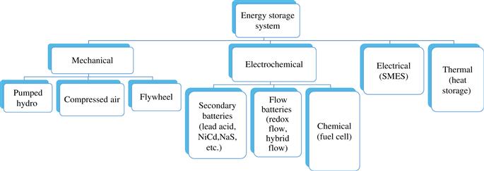
This section discusses energy storage technology that facilitates high penetration and integration of variable renewable energy sources in a microgrid. ESS has been utilized in power systems for several decades in the United States, and now the integration of renewable energy sources is creating demands for increasing DES sources [31,32]. ESS plays an extremely important role in improving the operating capabilities of microgrids. ESS can be divided into mechanical, electrochemical, chemical, electrical and thermal systems, as shown in Figure 1.11. In the following, an overview is provided of the major types of energy storage applied in microgrids.
1.7.1 Batteries
1.7.1.1 Lead-Acid Batteries
The lead-acid battery has over 100 years of history since its invention and is the most widely used rechargeable battery. Approximately 70% of lead-acid batteries are used for vehicles, 21% for communications, and 4% for other applications [33]. The benefits of lead-acid batteries include low cost, high efficiency and good surge capability. They are an excellent choice for uninterruptible power supply and can also be used for spinning reserve applications [34].
A high voltage can be achieved by simply connecting lead-acid battery cells in series. Each lead-acid cell, with a 2 V voltage, is made from a spongy pure lead cathode, a lead dioxide anode as well as a 20–40% solution of sulfuric acid that acts as an electrolyte. When the battery is discharging, a chemical reaction allows conduction between the anode and the cathode to generate electricity. The chemical reaction is reversible if the electrodes are supplied with voltage. That is the reason why lead-acid batteries can be recharged. The life cycle and the ability to tolerate deep discharges vary for different types.
No remarkable improvements have been achieved in the energy to volume ratio for a long time. Therefore, future battery research should pay more attention to other types of battery with more potential. Nevertheless, the lead-acid battery plays an important role today due to its cost-effectiveness. They are also easy to recycle. However, sometimes lead, which is a poisonous metal, can be a risk to the environment. Until more mature battery technologies appear, the lead-acid battery will still dominate the battery market.
1.7.1.2 Lithium-Ion Batteries
The light weight and quick response behavior make lithium suitable for making batteries. The power density of lithium-ion batteries is the best of all commercialized batteries. The voltage of a lithium-ion battery cell is 3.7 V, almost twice that of a lead-acid battery. The lithium-ion battery resembles a capacitor in the way it operates. There are three layers in lithium-ion battery. The first layer is the anode, and is made from a lithium compound. The second layer is the cathode and is made from graphite. The third layer is called the insulator, and it is located between the first and the second layer.
Lithium-ion has a very low self-discharge rate. In addition, the materials to make lithium-ion battery are abundant. The disadvantage is that lithium is expensive. Currently, cost and safety issues are the two main factors that impede the promotion of lithium-ion for widespread use in power systems.
Lithium-ion batteries are mainly used for small electronic devices like smartphones or laptops. For power systems, lead-acid batteries are more cost-effective at present, but lithium batteries have greater potential than other types of batteries. IBM is currently working on a project called Battery 500. The objective of this project is to develop a lithium battery that could store enough energy to power an electric vehicle for 500 miles.
1.7.1.3 Redox-Flow Battery
The electrolytes of redox-flow batteries can be exchanged. This feature makes it very easy to charge electric cars simply by refueling. However, the energy density of redox battery is very low, commonly 35 Wh/kg. But the Fraunhofer Institute in Germany claims that they could increase the redox-flow battery density up to the level of lithium-ion batteries (200 Wh/kg).
Other benefits of redox-flow battery include a long lifetime of about 40 years, and a capacity that can be easily increased by simply increasing the number of tanks and adding more electrolyte. With regard to grid storage, the capacity is very small, similar to that of flywheels, Superconducting Magnetic Energy Storage (SMES) or other battery storage types.
1.7.1.4 Sodium Battery
The sodium-sulfur battery is another type of battery under development. This technology has already been operated in some countries, such as Japan. The installed capacity of sodium battery is about 250 MW. The technological advantage of the sodium battery is its high power density, long battery lifetime (usually over 10 years) and high efficiency (up to 90%). But when this type of battery is operating, a high temperature (350°C) is required to liquefy the sodium. This constraint increases the difficulty and operational cost of sodium-sulfur batteries. Another drawback is that the sodium battery is very dangerous if the liquid sodium comes into contact with water in the atmosphere.
1.7.2 Flywheels
Flywheel energy storage unit (FESU) can supply immediate active power support for a renewable energy based microgrid. It has numerous merits such as high power density, high conversion efficiency and long life-span. In the past few decades, it has been used in uninterruptible power supplies where the short-duration power changes reduce the battery lifetime. In the context of autonomous energy production, flywheels are used in the field of transportation and in space applications for energy transfer and, particularly, to stabilize or drive satellites (gyroscopic effect) [35]. Flywheel energy storage is characterized by its long lifetime (typically 20 years) [36,37].
A flywheel is a disk with a certain amount of mass that can spin to store energy in kinetic form. To prevent the influence of gravity, the disk in flywheel ESS are built in perpendicular position of the rotor. Flywheels can be charged by electric motors when there is excessive electricity. It can also act as a generator when discharging.
Due to the existence of friction, eventually flywheels will lose some energy. Hence, minimizing friction can help to improve their efficiency. This goal can be realized through two approaches: the first one is to make a vacuum environment for the flywheel to spin in, ensuring there will be no air resistance. The second approach is to install a permanent magnet or electromagnetic bearing to make the spinning rotor float. The spinning speed of modern flywheel energy storage system can reach up to 16,000 rpm with a capacity of up to 25 kWh.
Flywheel have low maintenance costs, and their life-span can be long. There is no greenhouse emission or toxic material produced when flywheels are working, so it is very environment-friendly. The response time is very short. The drawbacks of flywheels are the small capacity and high power loss, ranging from 3% to 20% per hour.
1.7.3 Supercapacitor
The supercapacitor is developed from the electric double-layer theory. A two-layer capacitor is formed when the electrode is in touch with the electrolyte. Usually, the storage capacity of a supercapacitor is 20–1000 times that of the common capacitor. It has high power density and high energy conversion efficiency. Hence, it has attracted widespread attention. However, since the voltage of a single cell is low, a supercapacitor consists of numerous capacitors arranged in parallel or in series. Strictly speaking, the internal parameters of each capacitor are different and thus voltage imbalance may exist in supercapacitor and affect the operational reliability.
A practical supercapacitor for energy storage in microgrid requires a stack of many single cells connected in series [38]. Each cell consists of five layers with a porous separator in the center, a pair of porous electrodes on each side of it, and a pair of current collectors that congregate charges located at the end of each cell. The separator is an electrical insulator that prevents physical contact of electrodes but allows ion transfer between them [39–40]. The cells are packed and immersed into an electrolytic solution forming the double-layer charge distribution.
1.7.4 Comparison of Various ESS Technologies
Different types of energy storage technology are discussed in recent publications [41–44]. Characteristics of the different types of energy storage are compared in Tables 1.1 and 1.2. Large difference exists among different types of ESS. Thus, the best energy storage type should be chosen according to the practical microgrid application under consideration.
Table 1.1
Comparison of Characteristics for Different Types of Energy Storage
| Type | Energy Density (Wh/kg) | Power Density (W/kg) | Response Time | Continuous Discharge Time | Cycling Times |
| Flywheel | 5–30 | 400–1500 | <1 s | 1 s–15 min | Above 20,000 times |
| Compressed air | 30–60 | – | 1–10 min | Above 1–24 h | Above 100,000 times |
| Lead-acid | 30–50 | 75–300 | <10 s | 1 s–10 h | 2000 times |
| Lithium-ion | 75–200 | 150–300 | <10 s | 1 s–10 h | <10,000 times |
| Sodium-sulfur | 100–250 | 100–230 | <10 s | 1 s–10 h | 2500–6000 times |
| Supercapacitor | 5–10 | 5–10 | <1 s | 1 ms–1 h | 100,000 times |
| Superconducting magnetic | 1–10 | 1–10 | <5 ms | 1 ms–1 h | 100,000 times |

Table 1.2
The Advantages and Disadvantages of Different Types of Energy Storage
| Type | Advantages | Disadvantages |
| Flywheel | High power density, quick response | Low energy density |
| Compressed air | Large capacity, long Continuous discharge time | Limited location, slow response |
| Lead-acid | Large capacity, high energy density | Low power density, low Cycling times |
| Lithium-ion | High energy density | Small capacity, hard for large scale application |
| Sodium-sulfur | High energy density | Needs high temperature in working process |
| Supercapacitor | High power density, quick response | Low energy density, expensive |
| Superconducting magnetic | High power density, quick response, high Cycling times | Low energy density, expensive, magnetic pollution to environment |
Different applications have different objectives and requirements, needing different features of each ESS technology. Therefore, it is necessary to conduct a comprehensive comparison and assessment of all storage technologies. When choosing an ESS for a microgrid application, the best balance of energy density, power density, response time and lifetime needs to be chosen.
ESS technologies can be categorized depending on discharge time and energy-to-power ratio:
• Short discharge time (seconds to minutes) is suitable for those applications whose energy to power ratio is less than 1: capacitor banks, superconducting magnetic energy storage and flywheels.
• Medium discharge time (minutes to hours) is suitable for those applications whose energy to power ratio is between 1 and 10: flywheel energy storage, lead-acid batteries, lithium-ion batteries and sodium sulfur (NaS) batteries.
• Long discharge time (days to months) is suitable for those applications whose energy-to-power ratio is greater than 10: hydrogen (H2) and synthetic natural gas (SNG), pumped hydro storage, CAES, redox batteries.
1.7.5 Battery Energy Storage Modeling Consideration
The electrochemical model and equivalent electric circuit model are the common models for battery dynamic charging and discharging modeling. For the lead-acid battery, the simple equivalent circuit model, Thevenin equivalent circuit model, third order dynamical model and fourth order dynamical model are commonly used [45]. The fourth-order dynamical model proposed by Giglioli is a detailed model, but lots of experimental parameters are needed and the computation is complicated [46]. Figure 1.12 shows a typical constant-current discharging voltage characteristic curve of the nonlinear battery model proposed in [47].

As shown in Figure 1.12, the constant-current discharge voltage characteristic curve of battery can be divided into several parts, including the index-number characteristic part at the start of discharging and the rated characteristic part when the voltage change is small. The equivalent circuit model can be obtained by fitting the characteristic curve in Figure 1.12, as shown in Figure 1.13. The model has internal resistance R and a controlled voltage source E in series [47]. E and R are nonlinear functions of the SOC and temperature. Also, the internal resistance takes a slightly different value during the charging and the discharging period [48].

Battery energy storage system usually has a short lifetime and high cost, and thus its lifetime should be a significant factor for the control and optimization of microgrids. ESS lifetime varies greatly depending on its usage [49]. Hence, a detailed battery model is required for accurate lifetime estimation.
A physical battery model with aging effect estimation considering SOC and state of health (SOH) is presented in [50]. For this method, both the SOC and SOH of the battery are calculated and updated for the optimization. SOH is obtained by considering two major factors, i.e., the cyclation based state of health (SOHc) and the calendrical aging (SOHt) [49]. An example Lead–Acid Battery Life loss cost model is introduced in [51].