
Chapter seven
Produced Water Treatment
The treatment of effluents of oil and gas operations can sometimes be impacted by the presence of produced polymer. The current technologies and developments will be highlighted in this chapter.
7.1. Introduction
In hydrocarbon‐bearing formations, water is very often associated with oil and/or gas. After a period of time in production, this water – called formation water – will likely be produced along with the oil and/or gas at an increasing percentage (called the water‐cut) until little hydrocarbon is produced. In order to maintain the pressure in the reservoir and displace the fluids of interest, a common practice is to inject water into the formation over an extended period until the process is rendered uneconomical by the quasi‐absence of oil production. The result is the production of large quantities of water that require handling, treating, disposal, or reinjection. The associated treating and handling costs can be significant, ranging from a few cents to a few dollars per barrel, depending on the treatment facilities, oil density/viscosity, and other contaminants such as solids, forcing companies to develop strategies to tackle this issue.
Polymer flooding is one of the techniques that helps delay water breakthrough when implemented early enough. Even when this technique is deployed late in the life of the field, it can positively impact fluid ratios at the production side by decreasing the water‐cut and increasing the oil cut, resulting in substantial savings on water handling.
A question that often arises is the possible impact of polymers on surface facilities during oil/water separation and, afterward, on the water treatment facilities. This chapter will discuss these aspects, and possible solutions will be outlined. However, case‐by‐case approaches remain necessary to find the most economical solutions.
The most difficult aspect of designing appropriate facilities in the case of polymer injection is to predict the polymer's characteristics (hydrolysis, molecular weight) and breakthrough in the producers. This depends on several design parameters:
- How much pore volume is injected? If less than one reservoir pore volume is expected to be filled by the polymer slug, then it is very unlikely that the original polymer concentration will ever be reproduced. The same is true for viscosity.
- What will happen when switching back to water? Again, if less than one reservoir pore volume is expected to be filled by the polymer slug, then, when switching to water, the water probably will not push the polymer slug evenly, but rather will finger through it and lead to dilution. Also, the polymer will progressively be stripped from the chase water by adsorption in the virgin zones of the reservoir. In the producers, the concentration will therefore increase slowly, peak, and then decrease with a very long tail.
- What is the viscosity injected? A high polymer viscosity will greatly improve sweep efficiency, enlarging areal and volumetric sweep efficiencies and therefore delaying breakthrough. Retention is also satisfied more quickly when a higher concentration and viscosity is injected.
- What will be the characteristics of the produced polymer? How will the chemistry and molecular weight be changed during transit in the reservoir and through the production facilities? Researchers have observed that, in some cases, polymers experience changes in hydrolysis degree (increase) and molecular weight (decrease). This aspect will greatly impact the viscosifying and flocculating properties of the polyacrylamide.
Viscosity in the producer is very difficult to predict since the polymer can be rapidly degraded by the lifting systems or pumps, notwithstanding dilution within the reservoir. It is slightly less complicated to predict polymer concentration, especially with a proper 3D model and adequate keywords. As a rule of thumb, we can say that the maximum polymer concentration in the producer will be a function of the following dimensional parameters:
With Cpolymax = maximum polymer concentration likely to be observed in the producers; Cpolyinj = injected polymer concentration; retention factor = polymer retention (can be defined as a percentage of polymer lost); and reservoir swept = percentage of reservoir containing the polymer contacted by the water chase.
All parameters except the initial concentration injected have values between 0 (excluded) and 1. Values of theoretical produced polymer concentrations should therefore be much lower than the initial concentration injected, but the actual concentration is subject to flow anomalies such as channels or fractures that would otherwise contribute to earlier breakthrough of higher produced polymer concentrations. Locations where this may be problematic should be identified through tracer testing. In general, the breakthrough time can be approximated by looking at the production history, especially the time it took for the injection water to break through during the secondary waterflood.
An important aspect to consider is possible dilution when all the effluents from different production areas are pumped to the same central processing facility, especially when not all of these zones are under polymer injection. In that case, dilution will help drastically decrease the viscosity and concentration in the produced fluids, limiting the impact on the existing facilities.
7.2. Generalities
7.2.1. Produced Water Characteristics
The produced water composition will vary over the life of the field due to factors and interventions such as water injection (with composition different from formation water), reservoir stimulation, introduction of chemicals, bacterial activity, enhanced oil recovery (EOR) techniques, and so on.
Produced water is basically a mixture of water and hydrocarbons and can also contain a variable percentage of the following:
- Suspended solids, including clays
- Production chemicals
- Scales
- Corrosion products
- Traces of heavy metals
- Dissolved organics (hydrocarbon included)
- Dissolved gas (H2S)
- Dissolved iron
- EOR chemicals
Proper treatment is required before reusing or disposing of the produced EOR fluid. Various technologies exist, some of which will be described in the upcoming sections.
A polymer can have several impacts on the water treatment facility if/when it breaks through:
- Polymers act as a flocculant and can agglomerate suspended solids.
- A polymer can increase the viscosity of the water phase – assuming it has the right molecular weight and chemistry – therefore impacting the treatment facilities, where separation mechanisms are governed by gravity and whose performance can be understood and described using Stokes' law.
- A polymer acts as a friction reducer, decreasing drag at Reynolds numbers above 3000. It can partly suppress vortices in specific equipment, such as hydrocyclones.
- A polymer is an ionic macromolecule that can interact with charged particles or electrolytes, sometimes enhancing droplets' coalescence.
As a side note, polyacrylamides are strictly water‐soluble polymers. Unpublished studies showed that this polymer family was not present in crude oil and did not impact the crude refining processes. The possible influence on water treatment facilities will be discussed in the next sections.
7.2.2. Oil and Gas Processing
The principal function of surface facilities is (i) to separate oil, gas, water, and solids to deliver hydrocarbons meeting sales specifications and (ii) to dispose of the water.
The first step in this process is separating water from oil and, if present, gas from liquid. This is conventionally done in separators with various designs, using gravity, and heat where necessary, as the main drivers. Oil and gas are directed to specific treating facilities to polish oil to sales specifications, while water enters a secondary process in which the remaining oil and solids are removed before disposal.
This secondary process can involve various technologies based on filtration, gravity, coalescence, etc. A brief description will be given later of the possible impacts of polymers on overall efficiency.
7.3. Oil and Gas Separation
Two technologies – whose efficiency can be impacted by polymers – will be specifically discussed here.
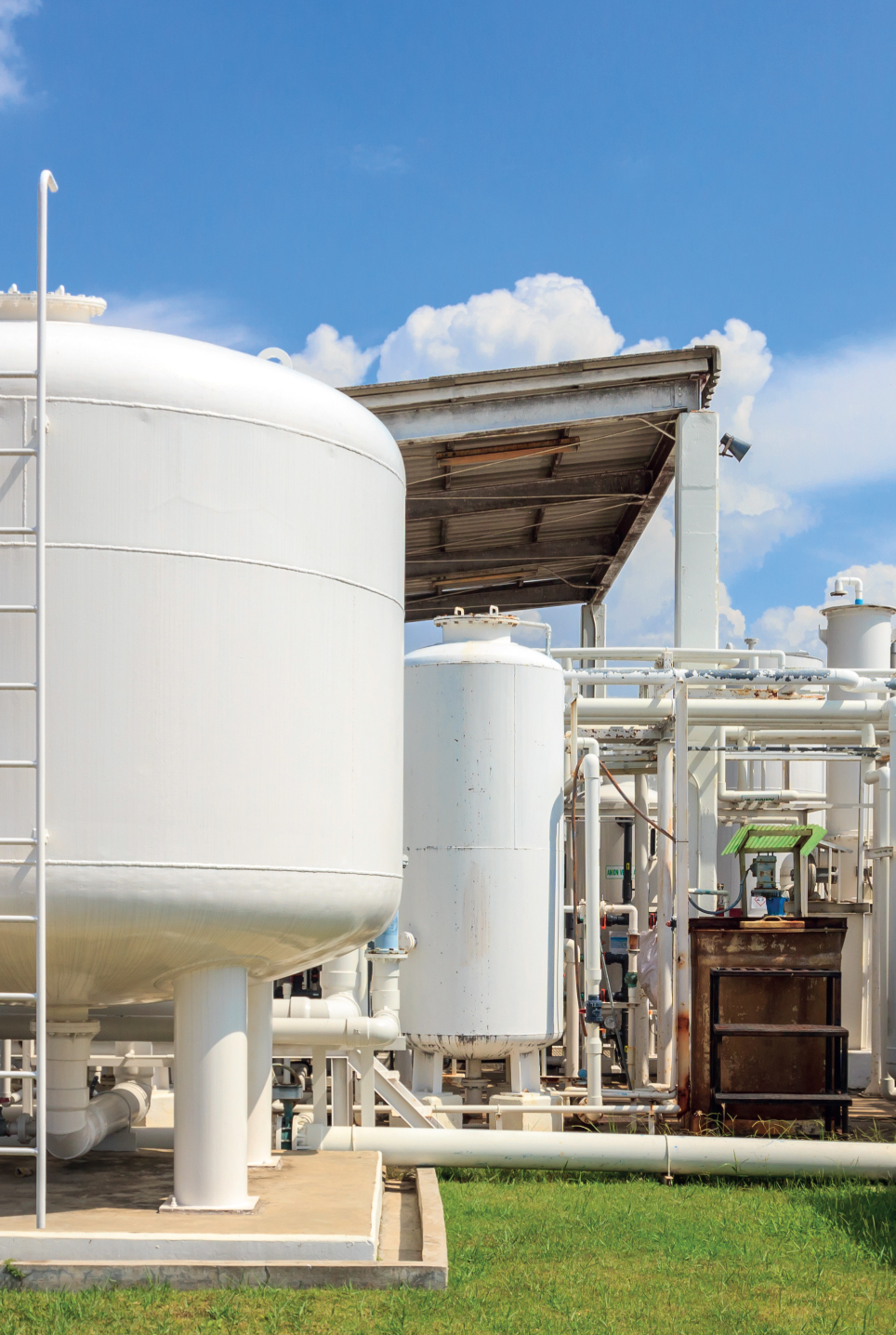
7.3.1. Separators
Separators can be horizontally or vertically orientated vessels and are usually composed of several devices or separation aids such as cyclones, filters, and plate packs (Figure 7.1). The separation performance depends on many factors such as flow rates and fluid properties. The main driver for separation is gravity: inside the gravity/coalescing zone (often the free‐water knockout tank), the oil droplets separate from the water thanks to density differences, as expressed by Stokes' law:
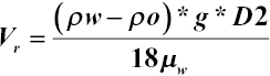

Figure 7.1 Free‐water knockout tank
where V r = drop/rise velocity (m/s); ρ w = water density (kg/m3); ρ o = oil density (kg/m3); μ w = water dynamic viscosity (kg/(m s); g = gravitational acceleration (9.81 m s−2); and D = drop diameter (cm).
Analysis of Stokes' law reveals that polymers can impact both viscosity (of the water phase) and droplet size by affecting coalescence. Predicting the viscosity of produced water containing polymers is very difficult, especially if the production equipment degrades the polymer backbones via mechanical shear, as is the case with some pumps and valves.
In theory, there are two ways to improve separation in cases where significant viscosity is produced:
- By breaking the viscosity via shear (or other methods). A drawback can be the creation of more stable emulsions.
- By increasing residence time in the separator. However, equations show that doubling the residence time will cause an increase in droplet diameter of only 19% [1].
Internal studies and field tests have shown that, generally speaking, polymers do not participate in oil emulsification and do not create intermediate rag layers. Also, the proportions of the phases obtained and the separation time are not affected by the presence of polymers. However, the compositions of the water‐dominant phase and oil‐dominant phase could be impacted either positively (better crude dehydration) or negatively (worse crude dehydration and higher oil content in the water) by the presence of polymers.
With regard to droplet size, studies performed with crude from the Daqing fields [2, 3] showed that polymers could enhance the coalescence of droplets below a certain concentration (and therefore a certain viscosity).
7.3.2. Heater Treaters
In a typical separation process, the produced fluid goes through three chambers: a high‐pressure separator, a low‐pressure separator, and a dehydrator. In the dehydrator, the wet oil is heated to reduce the viscosity of the continuous oil phase. This equipment can be categorized as mechanical or electrostatic dehydrators [4]. A mechanical heater is composed of a fire tube followed by a mechanical gravity separator. Electrostatic dehydrators use electrostatic fields to mobilize dispersed water without mobilizing the continuous oil; this is based on the fact that oil is almost nonpolar and nonconductive, whereas water is a polar and conductive molecule.
Issues have been reported in heavy oilfields with mechanical heater treaters and failures of fire tubes: a continuous temperature increase of the tube skin was observed after solids deposition occurred. The origin of this skin is probably the polymer flocculating solids in suspension, favoring wall deposition and skin formation. Remediation methods – such as scale inhibitor development, heat flux optimization, and installation of spray bars – were used to limit maintenance time and decrease the number of interventions [5, 6]. Also, a decrease in skin temperature is possible, to maintain operational efficiency [7]. Studies have shown that the use of electrostatic dehydrators is a preferred option in projects with polymer injection.
7.4. Water Treatment
7.4.1. Introduction and Generalities
Once the hydrocarbons have been separated from the bulk of the produced fluid, the water is directed to treating facilities designed to remove the remaining oil and solids. Equipment to remove oil and solids relies on different principles:
- Gravity separation (often with coalescing aids)
- Gas flotation
- Cyclonic separation
- Filtration
- Centrifuge separation
Chemical or biological methods can be introduced into the mix to remove specific components.
7.4.2. Gravity Separation
Gravity‐separation devices include American Petroleum Institute (API) separators, skim tanks, skim piles, and plate coalescers. Such equipment is usually rather inexpensive, but it requires a large footprint because of the residence time needed to favor coalescence of oil droplets. Oil concentration and particle‐size distribution are needed for the proper design of a gravity separator, which can render the process more complicated when an EOR method such as surfactant–polymer (SP) or alkali‐surfactant‐polymer (ASP) is implemented.
As discussed in the previous section, the principle of gravity separation can be described using Stokes' law:
where V r = drop/rise velocity (m/s); ρ w = water density (kg/m3); ρ o = oil density (kg/m3); μ w = water dynamic viscosity (kg/(m s); g = gravitational acceleration (9.81 m/s2); and D = drop diameter (cm).
Several conclusions can be drawn from the analysis of this equation [1]:
- The greater the difference in density between oil and water, i.e. the lighter the oil, the greater the rising velocity of the oil phase.
- Increasing the value of gravitational acceleration – for example, by centrifugal motion – will increase the separation velocity.
- The larger the oil droplet, the greater its rising velocity to the surface.
- The lower the water viscosity, the easier it is to treat the produced fluid. Temperature is therefore an important factor in water treatment, since it impacts viscosity.
Polymers can have an impact on water viscosity (depending on their concentration and molecular weight) and also on coalescence. Below a certain concentration, polymers can help coalescence by bringing together oil droplets [8]. However, when the concentration and viscosity increase, it becomes more difficult for the droplets to move and contact each other, decreasing both coalescence efficiency and rising velocity.
Water clarifiers (deoilers) are often used to favor the coalescence of oil droplets and facilitate separation. It is paramount to check the compatibility of these chemicals or any coalescing aid with produced polymers, since the polymers can interact with the clarifier and impact the overall efficiency of the process. Bottle tests can be performed to optimize the choice of the deoiler chemistry to maintain good separation efficiency.
7.4.2.1. Deoilers
Deoilers, reverse demulsifiers, coagulants, and flocculants are used to treat produced water containing oil, to enhance droplets' coalescence and accelerate the clarification process (Figure 7.2). Oil droplets usually bear a negative charge at their interface with water; they can be destabilized by adding chemicals with a cationic charge (coagulant) and then flocculated with either an anionic or a cationic product. The presence of residual anionic polymers coming from EOR will impact the dosage of cationic deoiler (linked to the cationic demand of water) needed to properly treat the residual oil [6, 9] (Table 7.1).

Figure 7.2 Deoiling test – use of optimized chemical compositions
Table 7.1 Cationic demand and coagulant addition required as a function of polymer concentration in the effluent
| Parameter | Values | |||||
| Polymer content (ppm) | 0 | 10 | 50 | 200 | 500 | 1000 |
| Cationic demand (meq.L−1) | 10 | 60–64 | 230–250 | 860–900 | 2090–2240 | 4120–4410 |
| Coagulant addition (ppm) | 10 | 10 | 30–32 | 128–133 | 279–296 | 471–494 |
The main issue with this approach when a polymer is present in the produced water is the quantity of sludge created by the reaction of both chemicals. It has been evaluated that treating a produced fluid containing 800 ppm of produced polymers with conventional deoilers creates 12 kg of sludge per cubic meter of produced water. This strategy should therefore be avoided to minimize the volume of sludge to be treated, handled, and disposed of.
Promising new chemical formulations and strategies have been developed and are being tested to maintain acceptable deoiling efficiencies in the presence of produced polymers [10-13]. These products are mainly nonionic.
7.4.3. Gas Flotation
With dispersed (induced) or dissolved gas flotation units (induced gas flotation [IGF] and dissolved gas flotation [DGF], respectively), large quantities of gas bubbles are injected into the water stream, where they attach to oil droplets, causing them to rise more efficiently to the surface where the oil can be recovered (Figure 7.3). Through gas introduction, oil droplets tend to rise to the surface as a result of three principles [14]:
- Increased vertical velocity of lighter components.
- Breakage of large vortices and conversion to smaller ones. The flow becomes more heterogeneous.
- Attachment of gas bubbles to contaminants, creating a stronger, upward buoyancy force.

Figure 7.3 Induced gas flotation device
An efficient process therefore requires a uniformly distributed flow of small gas bubbles with a velocity low enough to enable attachment to the oil droplets.
Internal studies have shown that IGF and DGF lose appreciable efficiency in the presence of polymers (up to 60%). Several mechanisms might explain the poor performance of the technology in that case:
- In the presence of polymers and possible interactions with droplets, it might be difficult for gas bubbles to attach to oil droplets and make them rise.
- Polymers might not favor droplet coalescence and growth.
- If a certain viscosity remains, where residual polyacrylamides show non‐Newtonian behavior, gas channeling can occur. In this case, preferential paths will be created through the fluid, leaving a large percentage of the oil droplets untouched.
- In theory, the size of IGF equipment should be increased proportionally to the increase of effluent viscosity.
Therefore, neither IGF nor DGF should be considered as a standalone treatment when polymers are expected or present in the produced water. A strategy to degrade the produced polymers might also be considered, to minimize side effects of increased produced‐water viscosity.
7.4.4. Cyclonic Separation
Hydrocyclones are widely used to deoil produced water: they are insensitive to motion or orientation and have the smallest footprint. Deoilers are pressure‐driven: they use fluid‐pressure energy to create rotational fluid motion. The main issue with polymers lies in the drag‐reducing properties they impart on the water phase: they are known to decrease the pressure drop by homogenizing the distribution of streamlines and smoothing the transition between laminar and turbulent flows. Therefore, it will be much harder to create a pressure drop and vortices when a polymer is present in the water, greatly affecting the process on which hydrocyclones are based. Studies have shown that, in the presence of polymers, the deoiling efficiency of hydrocyclones can be decreased by 60% [1]. The possible stabilization of oil droplets by polymers further erodes deoiling efficiency. Hydrocyclones with gas injection have shown some improvement but have are not seen widespread application in the oil and gas industry.
7.4.5. Centrifuges
Disk stack centrifuges (DSCs) are also used to remove oil in fluids containing up to 1000 ppm of oil‐in‐water (O/W) at the inlet. Deoiling efficiency up to 85% has been observed with 500 ppm polymers present. However, frequent maintenance is required due to the significant risk of failure caused by mechanical erosion.
7.4.6. Filtration
Different filters are used in the oil and gas industry to remove both solids and oil carry‐over. They can be used either to remove the coarse part or for polishing. For the sake of simplicity, we will define two major categories:
- Media filters: walnut‐shell filters and sand filters
- Membranes
7.4.6.1. Media Filters
7.4.6.1.1. Walnut‐Shell Filters
These filters are designed specifically to remove residual, dispersed hydrocarbons from produced water (Figure 7.4). They are often used as polishing equipment after IGF. No studies have been published on the impact of polymers on deoiling efficiency. However, internal studies have shown promising results; investigations are ongoing to test the limits of this system in the presence of polymers.

Figure 7.4 Principle of walnut‐shell filters
7.4.6.1.2. Sand Filters
In addition to the media type, sand filters differ from walnut‐shell filters in the method of backwashing. Unpublished studies have shown that this type of filter becomes inefficient when polymers are present in the water.
Several technology providers have worked on new materials and designs to improve deoiling efficiency in the presence of polymers:
- Siemens PerforMedia
- Schlumberger MYCELX technology
7.4.6.1.3. Siemens Perfor Media
This Siemens proprietary synthetic media is designed to handle up to 500 ppm O/W, targeting less than 10 ppm O/W residual in the effluents and removing 90% of solids with a size >10 μm. Yard tests were performed in 2017, in collaboration with SNF, utilizing synthetic effluents and polymers with characteristics close to what could be expected in produced water.
| Test conditions | Values | ||
| Flux (m3/hr/m2) | 24.4 | 30.5 | |
| Feed O/W (ppm) | 241 | 241 | |
| Feed polymer (ppm) | 493 | 484 | |
| Effluent O/W (ppm) | 6.2 | 16.5 | |
| Oil removal efficiency (%) | 97.4% | 93.2% | |
In addition to efficiently removing more than 90% of O/W, no change in polymer characteristics was observed during the treatment, opening the possibility to reuse the polymer for making‐up and hydrating a new viscous solution for injection.
7.4.6.1.4. Schlumberger MYCELX
The equipment as tested in the yard was composed of a coalescer, a proprietary filter media (Regen), and possibly a polisher. Tests were performed with O/W ranging from 500 to 1300 ppm and polymers with solution viscosities from 3 to 18 cP. Oil‐removal efficiency ranged for all tests between 95% and 97.5%, leaving the polymer's characteristics unchanged. Field tests corroborated the results observed in the yard.
7.4.6.2. Membranes
Membranes are usually divided in two categories (Figure 7.5): those that primarily retain particles (micro‐ and ultrafiltration) and those that primarily retain molecules and ions (nanofiltration and reverse osmosis) [15]. The way water moves through these membranes is different in the two categories. For micro/ultrafiltration (MF/UF), water moves through pores; whereas for nanofiltration and reverse osmosis, water moves through molecular structures. The pore size for MF ranges from 0.1 to 3 μm and for UF from 0.01 to 0.1 μm. Otherwise, variations in membrane technologies are almost unlimited: membrane packaging, flow direction, material, pressure drop, etc. can vary greatly from one type to another.

Figure 7.5 Membrane filtration processes
Two main families of MF/UF membranes are generally used: ceramic and polymeric. Ceramic MF/UF membranes are made from oxides, carbides, or metals. They are mechanically strong, they are chemically and thermally stable, and they can achieve high flux rates. This type of membrane can remove particles, oil, oxides, and organic matter. They normally perform better than polymeric membranes at removing residual oil in produced water but do require frequent backwash.
Polymeric membranes are generally quite inexpensive but also more fragile than ceramic membranes. Integrity testing is required to ensure that the membrane is not damaged and operates properly. Typical materials used for their construction are polyvinylidene fluoride (PVDF) and polyacrylonitrile (PAN).
Published and unpublished tests have shown that it is possible to treat produced water containing polymers without significant impairment of the membrane efficiency. The choice of pore size is paramount to maintain deoiling efficiency while allowing the polymer to pass through and be disposed of or reused [12].
7.5. Polymer Degradation
Depending on the polymer concentration, the viscosity of the produced effluents, and the water treatment facilities in place, it might be necessary in some cases to degrade the polymer to maintain acceptable cleaning performance.
To begin with, a few questions should be addressed. The first is linked to the characteristics of the produced polymer. Determining average parameters may require running experiments in the laboratory with a model polymer. In practice, the produced polymer will have a lower molecular weight and a higher degree of hydrolysis. Therefore, the native polymer should not be used to quantify the effects on water treatment facilities.
Some published field cases in China have shown that, on average, molecular weight, concentration, and viscosity were 50–80% lower than injected, with an increase of hydrolysis degree from 5% to 25%. As discussed in the previous section, this aspect is linked to both the injection strategy (required pore volume for injection) and degradation occurring in the production facilities (pumps, air exposure, sampling strategy).
The second question is, can the polymer be reused? Even with a lower molecular weight, the produced polymer can be reused to dissolve new polymer powder, generating a fresh solution, with a possible dosage decrease in the long term and therefore significant savings. This aspect should be investigated when selecting a water treatment process.
The produced polymer can have several benefits [16]:
- It can be reused to possibly decrease the amount of fresh polymer needed to reach the target viscosity, thus reducing operating expenses (OPEX). This has no impact on standard dissolution facilities.
- Any polymer remaining in the water will act as a friction reducer water is pumped for injection or disposal, thereby reducing the pumping energy required and increasing injection rates for the same pressure drop.
- If water is injected into a virgin part of the reservoir, the polymer in the water phase will act as a sacrificial agent by adsorbing onto the rock. Therefore, if chemical injection is envisaged, fewer chemicals will be lost by retention.
- Anionic polymers have other benefits, such as acting as clay stabilizers, sand control, and even anti‐corrosives.
In order to maintain good water treatment efficiency, it is possible to chemically or mechanically degrade the polymer or even remove it. Several methods can be considered [17-20]. A brief description will be given in the coming sections. However, not all are applicable in the field: it depends on local constraints, flow rates, and other characteristics of the effluents. A case‐by‐case approach must be used to find the most appropriate solution. Potential methods are as follows:
- Polymer precipitation with a coagulant
- Chemical degradation with an oxidizer
- Electro‐oxidation
- Mechanical degradation
- Ultrasonic degradation
- Thermal degradation
- UV – advanced oxidation process (Fenton reaction)
7.5.1. Polymer Removal
Removing polymers from previous effluents is possible but very costly and not applicable everywhere. In addition to requiring significant quantities of chemicals to react with the polymer, the creation and handling of large sludge volumes may render the process uneconomical [8]. The main techniques are as follows:
- Polymer flocculation with organic or inorganic cationic coagulants. The polymer precipitates along with the O/W and the solids. The dosage required is on a 1 : 1 basis.
- Electro‐coagulation. This process doesn't require chemicals but was not tested at large scales. Regular maintenance is needed to maintain acceptable removal efficiency.
- Precipitation with particles. A polymer is a flocculant. The addition of clays such as kaolinite will therefore remove the polymer from water. However, the dosage required to remove all polymers is prohibitive: 200 ppm of kaolinite are required to remove 1 ppm of polymer, and the sludge generated should be handled and treated.
7.5.2. Chemical Oxidation
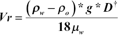
The generation of free radicals can break the polymer backbone, as discussed in Chapter 4. Common oxidizers used in the industry are sodium hypochlorite (NaClO – bleach), hydrogen peroxide, sodium persulfate, and magnesium peroxide. Studies have shown that bleach is the most effective oxidizer [11, 21]. Laboratory studies have shown that 200 ppm of NaClO are enough to reach a viscosity of 1 cP in less than 10 minutes (Figure 7.6). There is the possibility of generating bleach on‐site with electro‐chlorination units. Residual chlorine should be removed before dissolving fresh polymer, to avoid degradation. Excessive chlorine consumption can occur if other reducers are present in the water, such as H2S.
Figure 7.6 Chemical degradation of a polymer solution with hypochlorite in the presence or absence of H2S
7.5.3. Electro‐Oxidation
Electrodes can be used to generate a current that will help create hydroxy radicals to attack the polymer. Even though it has proven to be efficient at breaking viscosity, this approach also oxidizes the oil, creates foam, and leaves too many free radicals in the treated water.
7.5.4. Mechanical Degradation
Breaking polymer chains will rapidly lead to decreased viscosity. This can be achieved using constrictions found in valves, pumps, chokes, or strong agitation. Applying a pressure drop above 40 bar will dramatically affect the polymer size and solution viscosity (Figure 7.7).
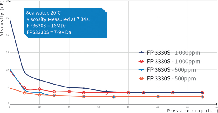
Figure 7.7 Mechanical degradation of two polymer solutions through a valve
7.5.5. Ultrasonic Degradation
The use of ultrasound technology can degrade the polymer and allow a reduction in viscosity in a couple of minutes [12] with powers from 120 to 160 W. This method is not affected by the presence of contaminants. However, no large units capable of handling oilfield flow rates are available, and significant power consumption might be required to obtain a timely result.
7.5.6. Thermal Degradation
It is possible to consider degrading polymers through heated tubes with a transit time of a couple of minutes (at temperatures above 180 °C). No chemicals are needed; but, on the other hand, scaling and corrosion issues should be expected for field brines with problematic compositions, in addition to very high energy consumption.
7.5.7. UV – Advanced Oxidation Processes
This technique uses UV (photolysis) or a combination of UV and radicals (photo‐Fenton). It is very effective at reducing viscosity in less than five minutes but requires significant power and large facilities to treat the volumes of effluents produced in oil and gas fields. The presence of other reducing agents, such as H2S, will also impact the efficiency of the process [22].
7.6. Conclusions and Discussion
Predicting the concentration and characteristics of the produced polymer is a difficult task. It will largely depend on the injection strategy and the equipment at the injection and production sides, which can change the molecular weight of the product injected. Moreover, transit through the reservoir can affect the hydrolysis and chemical size and composition of the product. Finally, dilution through commingled production can greatly impact the final viscosity arriving in the water treatment facilities. It is very difficult to reproduce in the laboratory typical effluents with oil, solids, and other contaminants. Care should therefore be taken when trying to model the possible impact of produced polymers on treating facilities.
In summary:
- Chemical and mechanical degradations are the most efficient techniques to reduce polymer viscosity. In particular, mechanical degradation can be performed inline with simple valves, at low cost; the main risk is the formation of more stable emulsions.
- Chemical degradation requires additional equipment and chemicals and is likely not available for offshore applications. A viscosity loss of 50% is enough to maintain good treatment efficiency in most cases; it can be achieved with a 50 bar pressure drop.
- Changing the demulsifiers/deoilers will likely be required if the polymer breaks through. New formulations exist to tackle this potential issue. A close collaboration with chemical suppliers is therefore mandatory.
- Gas flotation, hydrocyclones, and sand filters are affected the most by the presence of polymers, with deoiling efficiencies decreased by more than 50%.
- Walnut‐shell filters, membranes, and other proprietary media filters are the most promising technologies, especially when combined with coalescers (Table 7.2).
Table 7.2 Summary of existing water treatment technologies and their relative efficiency in treating produced water containing polymers
 |
Combinations of technologies might be required to efficiently treat effluents containing polymers: a coalescer with nutshell filters or other media filters for example.
The use of membranes can help reuse the polymer, thus decreasing the need for fresh product and allowing significant savings in OPEX.
To precisely analyze the polymer produced, it is also necessary to implement specific protective sampling techniques to ensure that no further change in polymer characteristics occurs.

References
- [1] Lake, L.W. (2007). Petroleum Engineering Handbook , vol. III & IV. SPE. ISBN: 978‐1‐55563‐126‐0.
- [2] Deng, S., Bai, R., Chen, J.P. et al. (2002). Produced water from polymer flooding process in crude oil extraction: characterization and treatment by a novel crossflow oil‐water separator. Separation and Purification Technology 29: 207–216. Elsevier.
- [3] Di, W., Guangzhi, A., Yan, C. et al. 1999. Rheology and stability of ior produced liquid in daqing oilfield. Paper SPE57318 presented at the SPE Asia Pacific Improved Oil Recovery Conference, Kuala Lumpur, Malaysia, 25–26 October.
- [4] Bartz, D. and Gotterba, J. 2014. Results of field operation of a distributed flux burner in a heater treater in a northern Canada heavy oil field; thermal performance and firetube life. Paper SPE170172 presented at the SPE Heavy Oil Conference, Alberta, Canada, 10–12 June. https://doi.org/10.2118/170172‐MS.
- [5] Wylde, J.J., Allan, K., McMahon, J. et al. 2011. Scale inhibitor application in northern Alberta – a case history of an ultra high temperature scale inhibition solution in fire tube heater treaters. Paper SPE141100 presented at the SPE International Symposium in Oilfield Chemistry, The Woodlands, Texas, USA, 11–13 April. https://doi.org/10.2118/141100‐MS.
- [6] Al‐Kalbani, H., Mandhari, M.S., Al‐Hadhrami, H. et al. 2014. Impact on crude dehydration due to back production of polymer. Paper SPE169718 presented at the SPE EOR Conference at Oil & Gas West Asia, Muscat, Oman, 31 March – 2 April. https://doi.org/10.2118/169718‐MS.
- [7] Zheng, F., Quiroga, P., Zaouk, M. et al. 2013. Electrostatic dehydration of heavy oil from polymer flood with partially hydrolyzed polyacrylamide. Paper SPE 165269 presented at the SPE Enhanced Oil Recovery Conference, Kuala Lumpur, Malaysia, 2–4 July. https://doi.org/10.2118/165269‐MS.
- [8] Fei, Z.X., Xin, L.L., Chan, W.Y. et al. (2007). Influence of residual polyacrylamide mass concentration upon waste water treatment with polymer flooding flocculation. Journal of Daqing Petroleum Institute 31.
- [9] Al‐Maamari, R.S., Sueyoshi, M., Tasaki, M. et al. 2014. Polymer‐flood produced‐water‐treatment trials. Paper SPE172024 presented at the Abu Dhabi International Petroleum Exhibition and Conference, Abu Dhabi, UAE, 10–13 November. https://doi.org/10.2118/172024‐MS.
- [10] Kaiser, A., White, A., Lukman, A. et al. 2015. The influence of chemical EOR on produced water separation and quality. Paper SPE 174659 presented at the SOE Enhanced Oil Recovery Conference, Kuala Lumpur, Malaysia, 11–13 August. https://doi.org/10.2118/174659‐MS.
- [11] Rambeau, O., Alves, M‐H., Loriau, M. et al. 2015. Chemical solutions to handle viscosified back produced water in case of polymer flooding. Paper SPE177501 presented at the Abu Dhabi International Petroleum Exhibition and Conference, Abu Dhabi, UAE, 9–12 November. https://doi.org/10.2118/177501‐MS.
- [12] Rambeau, O., Alves, M‐H., Andreu, N. et al. 2016. Management of viscosity of the back produced viscosified water. Paper SPE 179776 presented at the SPE EOR Conference at Oil & Gas West Asia, Muscat, Oman, 21–23 March. https://doi.org/10.2118/179776‐MS.
- [13] Ma, H., Abdullah, S., Shawabkeh, R. et al. 2017. Destabilization and treatment of produced water‐oil emulsions using anionic polyacrylamide. Paper SPE183665 presented at the SPE Middle East Oil & Gas Show and Conference, Manama, Kingdom of Bahrain, 6–9 March. https://doi.org/10.2118/183665‐MS.
- [14] Richerand, F. and Peymani, Y. 2015. Improving flotation methods to treat eor polymer rich produced water. Paper SPE174535 presented at the SPE Produced Water Handling and Management Symposium, Galveston, Texas, USA, 20–21 May. https://doi.org/10.2118/174535‐MS.
- [15] Hendricks, D. (2006). Water Treatment Unit Processes: Physical and Chemical . CRC Press – Taylor & Francis Group.
- [16] Thomas, A. (2016). Polymer flooding. In: Chemical Enhanced Oil Recovery (cEOR) – a Practical Overview (ed. L. Romero‐Zerón). InTech https://doi.org/10.5772/64623.
- [17] Guangmeng, R., Dezhi, S., and Meiling, W. (2006). Progress in the treatment technologies for wastewater from tertiary oil recovery in China. Industrial Water Treatment 26.
- [18] Go‐Yin, Y., Shan, G.L., Zhou, T.S. et al. (2006). Treating recycled oilfield produced water treatment technology by electrochemical oxidation/coagulation for corrosiveness reduction. Oilfield Chemistry 23.
- [19] Xueguang, Z., Wu, C., Ping, M., and Yangqiu, P. (2009). Advance on treatment technology for oil‐gas field operation flowback fluids in China. Advances in Fine Petrochemicals 10.
- [20] Wang, Z., Lin, B., Sha, G. et al. 2011. A combination of biodegradation and microfiltration for removal of oil and suspended solids from polymer‐containing produced water. Paper SPE140916 presented at the SPE America E&P Health, Safety, Security and Environmental Conference, Houston, Texas, USA, 21–23 April. https://doi.org/10.2118/140916‐MS.
- [21] Thomas, A., Gaillard, N., and Favéro, C. (2013). Some key features to consider when studying acrylamide‐based polymers for chemical enhanced oil recovery. Oil & Gas Science and Technology – Rev. IFP Energies Nouvelles https://doi.org/10.2516/ogst2012065.
- [22] Qiang, S., Guangxu, Y., and Shaohui, G. (2007). Experimental study on removal of polyacrylamide in the oilfield polymer‐bearing wastewater. Energy Environmental Pollution 21.