Now that we’ve seen how switches function, we will describe some of the features you may find supported on switches. The size of your network and its expected growth affect the way you use Ethernet switches and the type of switch features that you need. A network in a home or single office space can get by with one or a few small and low-cost switches that provide basic Ethernet service at high enough speeds to meet your needs with few extra features. Such networks are not expected to be complex enough to present major challenges in terms of network stability, nor are they expected to grow much larger.
On the other hand, a medium-sized network supporting multiple offices may need more powerful switches with some management features and configuration capabilities. If the offices require high-performance networking for access to file servers, then the network design may require switches with fast uplink ports. Large campus networks with hundreds or even thousands of network connections will typically have a hierarchical network design based on switches with high-speed uplink ports, and more sophisticated switch features to support network management and help maintain network stability.
Depending on their cost, switches may be provided with a management interface and management software that collects and displays statistics on switch operation, network activity, and port traffic and error counters. Many medium- and higher-cost switches include some level of management capability, and vendors typically provide management application software that is Web-based and may also allow you to login to the switch via a console port on the switch or over the network.
The management software allows you to configure port speeds and features on the switch; it also provides monitoring information on switch operations and performance. Switches that support the spanning tree protocol typically also support a management interface that allows you to configure spanning tree operations on each switch port. Other configurable options may include port speed, Ethernet auto-negotiation features, and any advanced switch features that may be supported.
Many switch management systems also use the Simple Network Management Protocol (SNMP) to provide a vendor-neutral way to extract operational information from a switch and deliver that data to you. That information typically includes the traffic rates being seen on switch ports, error counters that can identify devices that are having problems, and much more. Network management packages based on SNMP protocols can retrieve information from a wider range of network equipment than just switches.
There are multiple software packages available in the marketplace that can retrieve SNMP-based management information from the switch and display it to the network manager. There are also a number of open source packages that provide access to SNMP information and display that information in graphs and textual displays. See Appendix A for links to further information.
Another useful feature for monitoring and troubleshooting switches is called a packet mirror port. This feature allows you to copy, or “mirror,” the traffic from one or more ports on the switch to the mirror port. A laptop running a network analyzer application can be connected to the mirror port to provide network traffic analysis.
A mirror port can be a very useful feature that makes it possible for you to track down a network problem on devices connected to a given switch. Vendors have adopted a wide range of approaches to mirror ports, with different capabilities and limitations depending on their particular implementation. Some vendors even make it possible for mirrored traffic to be sent to a remote receiver over the network, which enables remote troubleshooting. Packet mirroring ports are not a standardized feature of switches, so vendors may or may not include this capability.
Switch traffic filters make it possible for a network manager to specify Ethernet frame filtering based on a number of parameters. The range of filters supported by switches varies widely among vendors. Lower-cost devices with no management interface won’t have any filtering capability, while higher-cost and higher-performance devices may offer a complete set of filters that the network manager can set.
By using these filters, a network manager can configure switches to control such things as network traffic based on the addresses of Ethernet frames, and the type of high-level protocol being carried in the frame. Filters may result in reduced performance, so you should check the switch documentation to determine the impact.
Filters work by comparing filter patterns, expressed as numeric values or protocol port names (e.g., http, ssh), against the bit patterns seen in Ethernet frames. When the pattern matches, then the filter takes some action, typically dropping the frame and thereby blocking the traffic.
Warning
Be aware that by using filters, you may cause as many problems as you are trying to resolve.
Filters that are designed to match patterns in the data field of the frame can cause issues when those patterns also occur in frames that you did not want to filter. A filter set up to match on one set of hex digits at a given location in the data field of a frame may work fine for the network protocol you are trying to control, but could also block a network protocol you didn’t even know existed.
This kind of filter is typically deployed to control the flow of some network protocol by identifying a part of the protocol in the data field of the Ethernet frame. Unfortunately, it’s hard for a network manager to anticipate the range of data that the network may carry, and depending on how it was constructed, the filter may match frames that were not intended to be filtered. Debugging a failure caused by a wayward filter can be difficult, since it’s usually not very obvious why an otherwise normally functioning Ethernet stops working for a specific application or for a certain set of stations.
Switch filters are often used in an attempt to gain greater control by preventing network interaction at the high-level network protocol layer of operations. If that’s why you’re implementing switch filters, then you should consider using Layer 3 routers that operate at the network layer and automatically provide this level of isolation without having to use manually-configured filters.
Layer 3 routers also provide filtering capabilities that can be easier to deploy since they are designed to work on high-level protocol fields and addresses. This makes it possible to easily write a filter that protects your network equipment from attack, for example, by limiting access to the TCP/IP management addresses of the equipment.
It can be a complex undertaking to set up filters correctly, as well as to maintain them once they are in place. As your network grows, you will need to keep track of which switches have filters in them, and to make sure that you can remember how the filters you have configured affect the operation of the network system, as it can often be difficult to predict the effect of a filter.
Documentation of the filters you have deployed and the way they are being used can help reduce troubleshooting time. However, no matter how well documented, these kinds of filters can cause outages. Therefore, you should regard the use of filters as something to be done only when necessary, and as carefully as possible.
A widely used feature typically included in higher-cost switches is the ability to group ports in a switch into virtual local area networks, or VLANs. At its simplest, a VLAN is a group of switch ports that function as though they are an independent switch. This is done by manipulating the frame forwarding software in the switch.
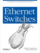
If the vendor supports VLANs on a switch, then they will provide a management interface to allow the network manager to configure which ports belong to which VLANs. As shown in Figure 2-1, we could configure an 8-port switch so that ports 1 through 4 are in one VLAN (call it VLAN 100), and ports 5 through 8 are in another VLAN (call it VLAN 200). Packets can be sent from station 10 to station 20, but not from station 10 to stations 30 and 40. Because these VLANs act as separate networks, a broadcast or multicast sent on VLAN 100 will not be transmitted on any ports belonging to VLAN 200. Therefore, the VLANs behave as though you had split the 8-port switch into two independent 4-port switches.
Vendors have provided other VLAN capabilities. For example, VLAN membership can be based on the contents of frames instead of just specifying which ports on the switch are members of a given VLAN. In this mode of operation, frames are passed through a set of filters as they are received on a switch port. The filters are set up to match some criterion, such as the source address in the frame or the contents of the type field, which specifies the high-level protocol carried in the data field of the frame. VLANs are defined based on their correspondence with these filters; depending on which set of criteria the frames match, the frames are automatically placed into the corresponding VLAN.
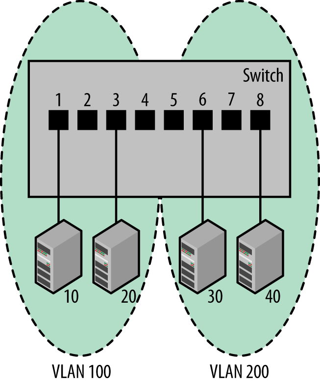
The IEEE 802.1Q VLAN tagging standard was first published in 1998. This standard provides a vendor-independent way of implementing VLANs. The VLAN tagging scheme used in 802.1Q adds 4 bytes of information to the Ethernet frame, following the destination address and preceding the type/length field. This increases the maximum frame size in Ethernet to 1522 bytes, as shown in Figure 2-2.
The 802.1Q standard also provides for priority handling of Ethernet frames using Class of Service (CoS) bits defined in the 802.1p standard. The 802.1Q standard provides space in the VLAN tag which allows you to use 802.1p CoS bits to indicate traffic priorities. There are three bits reserved for CoS values, making it possible to provide eight values (0-7) to identify frames with varying service levels.
VLANs are widely used in network designs to provide multiple independent networks. This helps control the flow of traffic by isolating traffic sent among specific groups of stations. Each VLAN functions as a separate switch, and there is no way to link separate VLANs other than connecting them together with a Layer 3 router. Building larger networks by linking VLANs with Layer 3 routers also avoids the propagation of broadcasts and multicasts seen on large Layer 2 networks, as it shifts the packet forwarding operations between the VLANs to a Layer 3 protocol.
Multiple Spanning Tree Protocol (MSTP) was developed in the 802.1s supplement to the 802.1Q standard. It is defined as an optional extension to RSTP to add the ability for switches supporting VLANs to use multiple spanning trees. This makes it possible for traffic belonging to different VLANs to flow over different paths within the network. The operation of the MST standard was designed to minimize the number of BPDUs required to build spanning trees for multiple VLANs, and to therefore be a more efficient system.
Note that if there is only one VLAN in use, then either the classic spanning tree or the more recent rapid spanning tree protocols are sufficient. Even when there is more than one VLAN, classic and rapid spanning tree will still be able to block loop paths. The multiple spanning tree protocol provides a more efficient model of operation based on multiple spanning tree (MST) “regions” that can each run multiple MST instances. The inclusion of regions requires that the network administrator configure MST bridges to be members of specific regions, making MST more complex to set up and operate.
While the MST standard provides advantages in terms of structuring a large system into regions, it also requires more effort up front in order to understand the configuration requirements and to implement them in your switches. MSTP is optionally provided on some switches, typically those that support large numbers of VLANs. However, classic STP and RSTP remain the most widely-used versions of spanning tree, given their “plug and play” operation and their ability to create an effective spanning tree for the vast majority of network designs.
Managing the priority of traffic flow to favor certain categories of traffic over other categories when congestion occurs is another capability of switches. The 32-bit field added by the IEEE 802.1Q standard provides support for traffic prioritization fields to utilize eight different Class of Service values as well as the VLAN tag.
The 802.1p standard provides traffic prioritization levels that are carried in the 802.1Q CoS tag and used to tag a frame with a priority value, so that certain traffic may be favored for transmission when network congestion occurs on a switch port. When CoS has been configured on a switch port, then the Ethernet frames that are not tagged with a high priority are the first to be dropped, should congestion occur on the port.
If your switch supports these features, you will need to consult the vendor documentation for instructions on how to configure them. While the IEEE standards describe the mechanisms that make these features possible, the standards do not specify how they should be implemented or configured. That’s left up to each vendor to decide, which means that the vendor documentation is the place to find the details on how to use these features in a given switch.