
In this chapter, we will show some of the basic ways switches can be used to build an Ethernet system. Network design is a large topic, and there are many ways to use switches to expand and improve networks. We will focus on just a few basic designs here, with the goal of providing a brief introduction to network design using Ethernet switches.
Switches provide multiple advantages in network designs. To begin with, all switches provide the basic traffic filtering functions described earlier, which improves network bandwidth. Another important advantage of modern switches is that the internal switching circuits allow traffic flows to simultaneously occur between multiple ports. Supporting multiple simultaneous flows of traffic, or “conversations,” between the ports is a major advantage of switches in network designs.
An important way in which a switch can improve the operation of a network system is by controlling the flow of traffic. The ability to intelligently forward traffic on only those ports needed to get the packet to its destination makes the switch a useful tool for the Ethernet designer faced with continually growing device populations and increasing traffic loads.
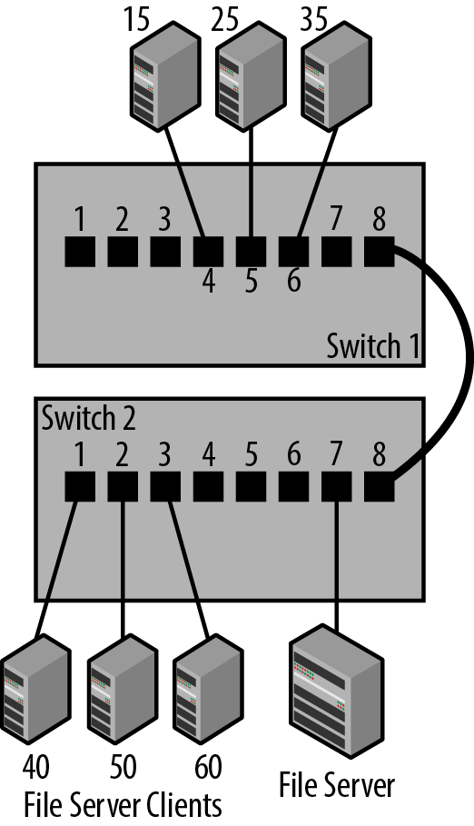
The traffic control provided by the internal address database can be exploited to help isolate traffic. By locating client and server connections on switches to help minimize network traffic, you can keep the traffic between a set of clients and their file server localized to the ports on a single switch. This keeps their traffic from having to traverse the larger network system.
Figure 3-1 shows a set of clients and their file server connected to a single switch, Switch 2, which isolates their traffic from the rest of the network connections in the building. In this design, all of the local traffic among clients 40, 50 and 60 and their file server stays on Switch 2 and does not travel through any other switches in the building.
When installing a switch, you can improve your network’s operation by being aware of the traffic flows and designing the network so that the traffic between a cluster of clients and their server(s) stays local. You may not be able to do this for all clients in a building, but any clients and servers that you can keep on a single switch, or small group of switches, will help minimize the amount of traffic that has to cross all switches in your network.
The example in Figure 3-1 reveals another important issue, which is that the links used to connect switches together should be high-performance links. Links between switches are called uplinks, since network tree diagrams are typically drawn with the switches arranged in a top-to-bottom hierarchy. The top-most switch is the core switch, which functions as the core of the network system by linking all other switches.
Linking the edge switches directly to the core in this fashion minimizes the number of switches, or switch hops, that the network traffic must cross to get from one computer to another in your network. Uplinks connect one switch to the next, leading up to a higher level of the network (core). Traffic travels in both directions over the uplinks.
Another advantage of switches is that they can link multiple network connections that run at different speeds. Any given connection to a switch port runs at a single speed, but multiple computers can be connected to the same switch, with the connections operating at different speeds. Depending on its cost and feature set, you may find that your switch has a couple of ports that are described as uplink ports. These ports typically support higher speeds than the rest of the ports on the switch, and are intended for making a connection up to the core switches, hence the term “uplink.”
Tip
If you want to use the latest network jargon, you could say that the uplink ports are used to create “northbound” connections to the core of your network.
Switch ports can run at different speeds because a switch is equipped with multiple Ethernet interfaces, each capable of operating at any of the speeds supported on the interface. A switch can receive an Ethernet frame on a port operating at 1 Gb/s, store the frame in port buffer memory, and then transmit the frame on a port operating at 10 Gb/s.
Tip
Filling the port buffer and causing congestion and dropped frames is more likely to occur when receiving on a 10 Gb/s port and sending on a 1 Gb/s port. This is due to the large difference in speeds and the longer time it takes to send a frame out the 1 Gb/s port.
In Figure 3-2, three edge switches are shown, each with one of their uplink ports connected to a fourth switch located at the core of the network. While the uplink ports operate at 10 Gb/s, most of the station connections are at 1 Gb/s except for the file server, which is connected to a 10 Gb/s port.
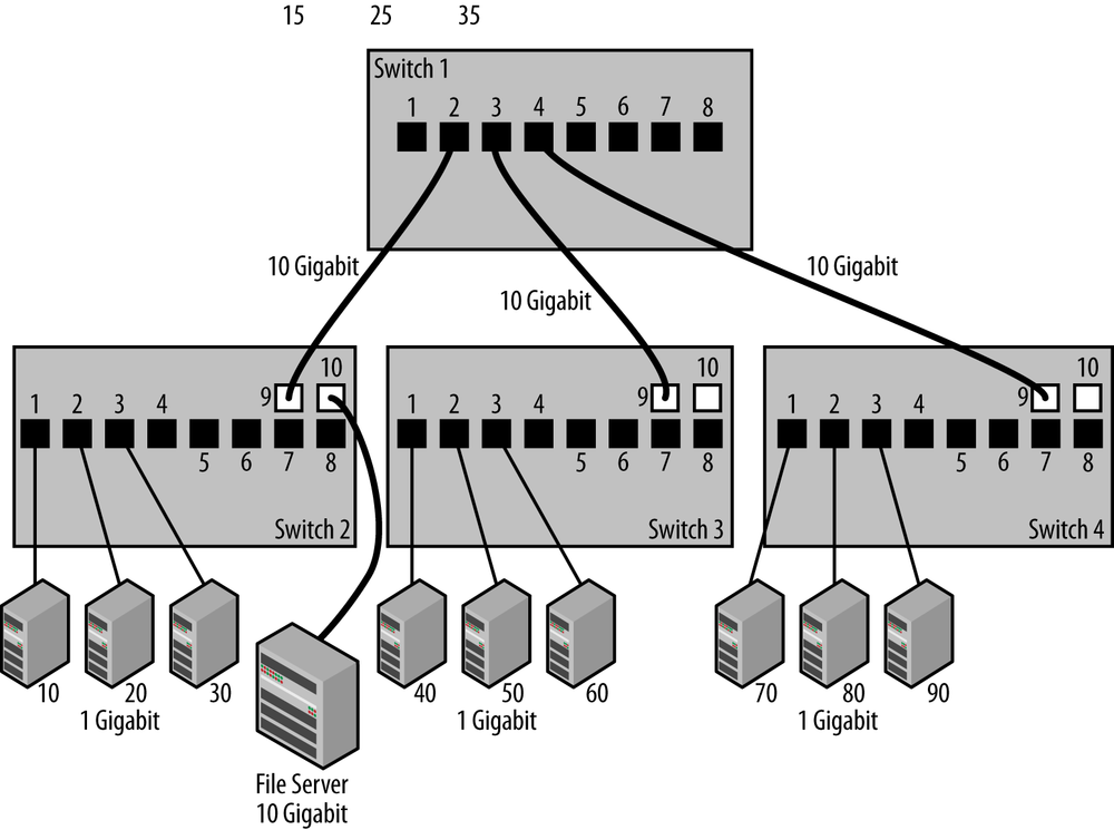
This connection shows that it’s possible to connect the server to one of the uplink ports, since there’s nothing that prohibits an uplink port from operating as a station port. Uplink ports typically operate at higher speeds, with larger packet buffers to handle traffic that arrives at higher speeds on the uplink port (10 Gb/s) and is destined for a slower station port (1 Gb/s). For that reason, while you usually want to save these ports for uplink purposes, they can also be used to connect to a heavily-used server machine.
The main reason you want uplinks to run faster is that there may be traffic from multiple stations connected at 1 Gb/s attempting to get to a single server on a separate switch. If the uplink connections were also running at 1 Gb/s, then there could be congestion and dropped frames, which can cause reduced performance for the computers sending data.
The port buffers on a switch are designed to hold just a few packets for a short period, which allows for a small amount of congestion. If the buffers were too large there could be increased packet delay and variation in packet delivery times, causing problems for certain kinds of applications. If there is a lot of traffic continually being sent from clients into one or more congested ports, the switch will run out of space in the port buffer memory, and will simply drop the incoming packets until space becomes available.
Tip
Local area networks are not designed to provide guaranteed packet delivery. If the system becomes congested, packets are dropped. The TCP/IP network protocol, in turn, is designed to respond to dropped frames by automatically throttling the traffic rate. In other words, dropped frames are normal and in fact are required to allow TCP/IP to detect and respond to network congestion.
To see how this works, let’s take the example shown in Figure 3-2. Suppose that the three stations, 70, 80, and 90 on Switch 4, all need to retrieve files from the file server on Switch 2. File service traffic tends to be high bandwidth; you could easily end up with three 1 Gb/s streams from the file server to the stations on Switch 4. If the uplink connections are operating at 1 Gb/s, then the switch ports in the path between the stations on Switch 4 and the file server on Switch 2 will become congested and will drop the frames that cannot fit into the already-full port buffers.
If, on the other hand, you link the switches together with 10 Gb/s uplinks, then you have a 10 Gb/s path from the file server on Switch 2 into Switch 4, and all three stations on Switch 4 will be able to interact with the file server at their maximum network rate of 1 Gb/s, without causing major congestion on the uplink paths. Packets received at 1 Gb/s from the stations will be sent ten times as fast, at 10 Gb/s, over the uplinks; this rapidly drains the uplink port buffers and ensures that there is buffer space available for more traffic from other stations.
Tip
Another possible design is to connect the server directly to the core switch on a 10Gb/s port.
The connection method shown here for the uplinks illustrates a couple of major advantages of switches: the ability to provide large amounts of packet switching performance inside the switch and the capacity to support multiple simultaneous traffic flows between stations and the file server. Every port on the switch in our example is an independent network connection, and each station gets its own 1 Gb/s dedicated full-duplex Ethernet path directly into the switch. Multiple station conversations occur simultaneously in both directions (data from the computer and replies to the computer), providing high performance and minimizing network delay.
Referring back to Figure 3-2, this means that while station 70 and the file server are communicating, station 80 and station 10 can be communicating at the same time. In this configuration, the total network bandwidth available to stations becomes a function of the ports to which each station is connected, and of the total packet switching capacity of your switch. Modern switches are equipped with switching fabrics that can provide many gigabits per second of switching capacity, and high-end switches will provide up to several terabits of packet switching capacity.
The speed of the switching fabric is only one important consideration when it comes to moving frames through a switch. As we’ve seen, high traffic rates coming into the switch from multiple ports, all destined for a single server port on the switch, will always be an issue, since the server port can only deliver packets at its maximum bit rate, no matter how many packets are sent to it at any given moment.
When multiple flows occur, it’s possible to overrun the capability of the output port, no matter how much internal packet switching capacity the switch may have. The switch will start dropping frames when it runs out of buffer space to store them temporarily. A dropped frame causes the network protocol software running on the computer to detect the loss and retransmit the data. Too many data retransmissions caused by excessive congestion on an output port can lead to a slow response for the application that is trying to talk to the server.
Traffic bottlenecks such as these are an issue in all network designs. When linking switches together, you may encounter situations where a bottleneck occurs when all the traffic from multiple switches must travel over single backbone links connecting two core switches. If there are multiple parallel connections linking the core switches, the spanning tree algorithm will ensure that only one path is active, in order to prevent loops in the network. Therefore, the ports of the switches that feed the single inter-core-switch link could be facing the same situation as the oversubscribed server port mentioned previously, causing the core switch ports to drop frames. In sufficiently large and busy network systems, a single inter-switch link may not provide enough bandwidth, leading to congestion.
There are several approaches that can be taken to avoid these problems in network systems. For example, the IEEE 802.1AX Link Aggregation standard allows multiple parallel Ethernet links to be grouped together and used as a large “virtual” channel between backbone switches.[16] Using link aggregation, multiple Gigabit Ethernet links can be aggregated into channels operating at two, four, and eight gigabits per second. The same is true for 10-Gigabit links, providing a channel operating up to 80 gigabits per second. This approach can also be used between a switch and Ethernet interfaces in high-performance servers to increase network bandwidth.
Another approach is to use Layer 3 routers instead of Layer 2 switches, since routers don’t use the spanning tree algorithm. Instead, routers provide more sophisticated traffic routing mechanisms that make it possible for network designers to provide multiple parallel connections for backbone links that are simultaneously active.
Network design refers to the way that switches are interconnected to produce a larger network system. Any network with more than just a few switches, and especially any network that is expected to grow, will benefit from a hierarchical network design that results in a system that is higher performance, more reliable, and easier to troubleshoot. Implementing a network design, and thus providing a plan for optimizing network operation and growth, pays major dividends in terms of network performance and reliability.
Networks that grow without a plan often result in systems with switches connected together in such a way that there are more switches in the traffic paths than necessary. This, in turn, leads to more complex “mesh” designs that are harder to understand and troubleshoot. Another name for the result of network growth with no plan is “fur ball” design. (Or perhaps it should be called “hair ball.”) Systems that “just grew” may also develop traffic bottlenecks whose presence and location are mysterious to the network administrator.
It’s a fact of life that networks often grow; without an adequate design in place they will grow randomly, becoming ever more complex and difficult to understand. A simple hierarchical network design based on two or three “layers” minimizes the number of switches needed, improving traffic flow and resulting in improved network performance and reliability. Other important advantages are that the network will be more stable and understandable as the system grows over time.
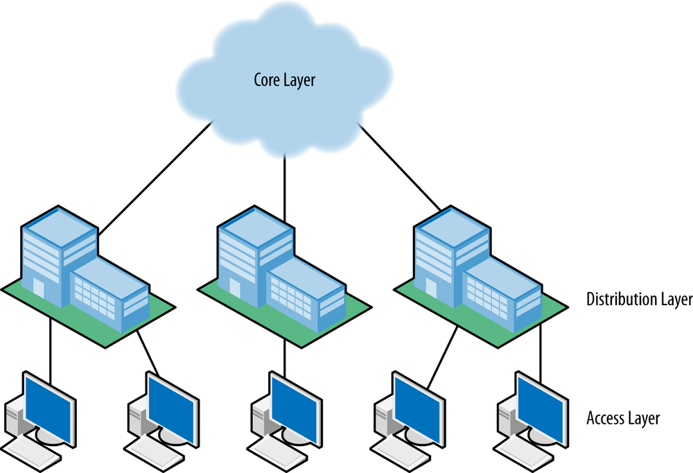
The most widely deployed design for networks that support standard offices and cube space in a campus of buildings is based on a hierarchical system of three layers: Core, Distribution, and Access, as shown in Figure 3-3. The core layer contains the high-performance switches that connect all buildings on a campus together. Each building has a distribution point, which contains the medium-performance switches connecting the building to the core and also connecting to the access switches inside the building. Finally, there is an access layer comprised of switches, which connects to all devices in the building; the access layer switches are connected in turn to the distribution switches. If there is only a single building, then the distribution and access layers are the only ones needed, with the distribution layer functioning as the building core.
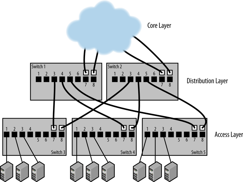
Inside each building, the access switches are connected directly to the distribution layer, and not to each other, as shown in Figure 3-4 It is essential that the uplinks of the access switches are connected only to the distribution layer switches, in order to avoid creating a set of horizontal paths between the access switches with a much more complex mesh structure. A major benefit of this design is that it reduces the number of switches in the network path between communicating Ethernet devices. That, in turn, decreases the impact of switch latency, and also reduces the number of bottlenecks affecting network traffic.
This design also minimizes the number of potential loop paths, which helps the spanning tree protocol converge on a set of paths more rapidly. This can become especially important after a power failure in a complex network, when all switches come back up at the same time and spanning tree must work to stabilize the entire set of network paths simultaneously. A hierarchical network design also makes it easier to provide high bandwidth uplinks, which helps prevent major bottlenecks and keeps spanning tree working well under all network load conditions.
Establishing and maintaining a network design requires documentation and attention to detail. Everyone involved in maintaining the network needs to understand the design in use and the benefits of maintaining a good network structure. You will find further reading on network design in the Appendix A.
As we’ve just seen, there are multiple reasons for minimizing the number of switches in the network path between devices. The 802.1D bridging standard provided yet another reason when it recommended a maximum network diameter of seven hops, meaning seven switches in the path between any two stations.
The recommended limit on the number of switches originated in a concern about round-trip packet delays with seven switches in a given path, providing 14 switch hops in a total round trip. A time-sensitive application sending a frame from one end of the network to the other and receiving a reply would encounter 14 switch hops, with the potential for an impact on the performance of the application, because of the time required to transit 14 switches.
The seven hop recommendation was in all versions of the 802.1D standard up to 1998. Subsequent versions of the standard removed the seven hop recommendation from the standard. However, in large network designs your network design should serve to keep the total number of switch hops to a minimum.
Network systems support access to the Internet and to all manner of local computing resources, making them essential to everyone’s productivity. If the network fails, it will have a major impact on everyone’s ability to get their work done. Fortunately, network equipment tends to be highly reliable, and equipment failures are rare. Having said that, network equipment is just another computer in a box. There are no perfect machines; at some point you will have a switch failure. The power supply may quit working, causing the entire switch to fail, or one or more ports may fail. If an uplink port fails, it could isolate an entire downstream switch, cutting off network access for every station connected to that switch.
One way to avoid network outages due to a switch failure is to build resilient networks based on the use of multiple switches. You could purchase two core switches, call them Switch 1 and Switch 2, and connect them together over parallel paths, so that there are two links between them in case one of the links fails. Next, you could link each of the access switches that connect to stations to both core switches. In other words, on each access layer switch, one of the two uplink ports is connected to core Switch 1 and the other uplink port is connected to core Switch 2.
Figure 3-5 shows the two core switches, Switch 1 and Switch 2, connected together over two parallel paths to provide a resilient connection in case one of the links fails for any reason. The aggregation switches are each connected to both core switches, providing two paths to the network core in case any single path fails.
At this point you should be asking, “But what about spanning tree? Won’t it shut down those parallel paths between resilient switches?” The answer is yes, spanning tree will block one of the two paths to ensure that there are no loop paths in the network system. The path will stay blocked until one of the active links fails, in which case RTSP, responding quickly to a detected change in the network, will immediately bring the backup paths into operation.
Figure 3-6 shows the resilient design after spanning tree has suppressed the loop paths by blocking the forwarding of packets on certain uplink ports. The ports that are blocked are shown with a “B.” If you know the MAC addresses and bridge IDs for each switch, then you can calculate, based on the operation of the spanning tree protocol, exactly which ports will be blocked to prevent loop paths.

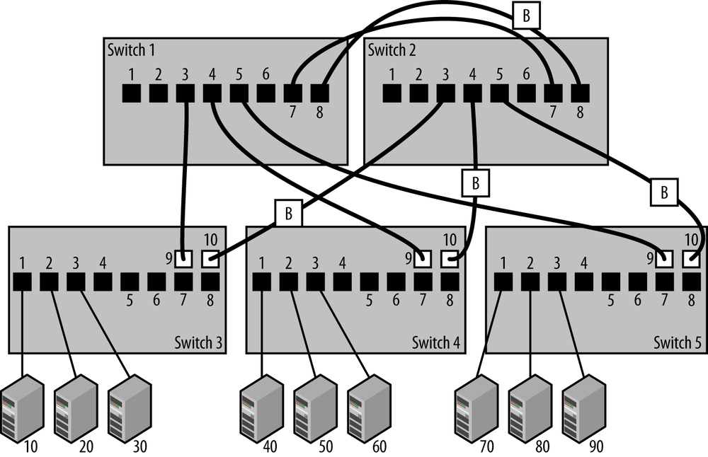
But you don’t need to know how things work at that level of detail. Instead, spanning tree will function automatically, and block one of the two paths creating a loop. The Ethernet link stays up and connected on the blocked port, but no traffic is forwarded over it. If the remaining active path should ever fail, then spanning tree will automatically re-enable the blocked port to bring the link back into operation.
The combination of dual core switches, dual uplinks, and spanning tree provides a resilient design that can survive the failure of one of the core switches and/or one of the dual uplinks from the aggregation layer switches. However, this is a higher cost and higher complexity design that requires both a larger budget and an understanding of how to connect switches for resilience. This design also has the disadvantage of providing only resiliency. All of the access switch links to Switch 2 are in the blocking state, and Switch 2 does not carry any traffic unless there is a failure of Switch 1.
If your network uptime needs are not so stringent as to require the kind of high uptime and automatic failure recovery provided by this design, then you could get by with keeping a spare switch on hand and using it to replace failures when they occur. It’s all a matter of your tolerance for network downtime and how much you are willing to invest in avoiding outages with automatic recovery systems.
Network design issues such as these require a good deal of knowledge about the mechanisms used to direct the flow of traffic through various devices such as switches and routers. This is also an area that is undergoing rapid evolution, and new mechanisms for moving traffic around large networks are continually being invented and tried out in the marketplace.
A router is a device that operates at the “Network” layer, or Layer 3 of the OSI network reference model. It helps to understand that the OSI layers are not derived from physics or the natural laws of the universe. Quite the opposite. Instead, the OSI layers are arbitrary definitions used to group the various details involved in computer communications into associated tasks called layers. This was done as a way to help clarify the tasks and to structure the development of the standards needed to achieve the communication tasks.
Like many other human endeavors, the evolution of computer communications technology has not followed a completely logical development path. For example, local area networks were defined as operating at Layer 2 because that’s what the people developing the standards wanted: a local network that carried data between computers located at a given site. Layer 2 standards describe local area networks operating at the Data Link Layer, and were not intended to deal with the issues of interconnecting large numbers of networks.
More sophisticated protocol operations based on structured addresses and capable of dealing with large numbers of networks were defined at Layer 3, the Network Layer. Switches operate at Layer 2 using only the information found in Ethernet frames, and routers operate at Layer 3 using high level network protocol packets carried in the data field of Ethernet frames, such as those packets defined in the TCP/IP protocol suite. Both Layer 2 and Layer 3 switches use Ethernet frames, but the addressing information used by the switch to make a packet forwarding decision is very different.
Routers are frequently used in large campus and enterprise networks, as well as the Internet itself. At the network layer of operation, you can find a wider range of mechanisms for interconnecting large network systems. While routers are more complex to configure than switches, the advantages they can provide offset the added complexity of their operation for many network managers.
In operation, a router receives and unpacks the Ethernet frames, and then applies rules to deal appropriately with the high-level protocol data that is carried in the data field of each Ethernet frame. When a router hears an Ethernet broadcast, it does the same thing all other stations must do: it reads the frame in and tries to figure out what to do with it.
Since routers move packets around based on higher-level protocol addresses, they do not forward Ethernet broadcast or multicast packets. Broadcast or multicast packets sent from a client station attempting to discover a service on a server connected to the same local network, for example, are not forwarded to other networks by the router, because the router is not designed to create a larger local area network.
Dropping broadcasts and multicasts at the router interface creates separate broadcast domains, protecting a large network system from the high multicast and broadcast traffic rates that might otherwise occur. This is a major advantage, both as a result of the reduced traffic levels, and the reduction in computer performance issues that can be caused by floods of broadcast and multicast packets.
Dividing networks into multiple, smaller Layer 2 networks by linking them with Layer 3 routers also improves reliability by limiting the size of the failure domain. In the event of such failures as packet floods caused by loop paths, a failing station that is sending continuous broadcast or multicast traffic, or hardware or software failure resulting in a failure of spanning tree, the size of the failure domain is limited by using Layer 3 routers to link networks.
However, creating smaller Layer 2 networks and linking them with Layer 3 routers also limits the number of stations that can interact when using discovery services based on Layer 2 multicast and broadcast. That, in turn, may cause challenges for network designers who are attempting to grow their network and limit the size of their failure domains while also keeping their users happy.
Users are happiest when everything “just works,” and are often insistent on large Layer 2 networks to keep automatic service discovery working for the largest number of computers. However, when a large Layer 2 network fails, users may suddenly discover that network reliability based on smaller networks connected with Layer 3 routers is more important to them than the convenience of widespread Layer 2 service discovery. See Appendix A for more information on network design issues.
Although both Layer 2 switches (bridges) and Layer 3 switches (routers) can be used to extend Ethernets by building larger network systems, bridges and routers operate in very different ways. It’s up to you to decide which device is best suited to your needs, and which set of capabilities is most important for your network design. Both bridges and routers have advantages and disadvantages.
- Bridges may provide larger amounts of switching bandwidth and more ports at lower cost than a router.
- Bridges may operate faster than a router, since they provide fewer functions.
- Bridges are typically simpler to install and operate.
- Bridges are transparent to the operation of an Ethernet.
- Bridges provide automatic network traffic isolation (except for broadcasts and multicasts).
- Bridges propagate multicast and broadcast frames. This allows broadcasts to travel throughout your network, making stations vulnerable to floods of broadcast traffic that may be generated by network software bugs, poorly designed software, or inadvertent network loops on a switch that doesn’t support the spanning tree protocol.
- Bridges typically cannot load-share across multiple network paths. However, you may be able to use the link aggregation protocol to provide load sharing capabilities across multiple aggregated links.
- Routers automatically direct traffic to specific portions of the network based on the Internet Protocol (IP) destination address, providing better traffic control.
- Routers block the flow of broadcasts and multicasts. Routers also structure the flow of traffic throughout a network system based on Layer 3 network protocol addresses. This allows you to design more complex network topologies, while still retaining high stability for network operations as your network system grows and evolves.
- Routers use routing protocols that can provide information such as the bandwidth of a path. Using that information, routers can provide best-path routing and use multiple paths to provide load sharing.
- Routers provide greater network manageability in terms of access control filters and restricting access based on IP addresses.
- Router operation is not automatic, making routers more complex to configure.
- Routers may be more expensive and may provide fewer ports than switches do.
The state of the art for bridges and routers is constantly evolving, and today many high-end switches are capable of operating as bridges and routers simultaneously, combining Layer 2 bridging and Layer 3 routing capabilities in the same device, as described in Multilayer Switches. You need to evaluate these approaches to establishing a network design and building a network system, given the requirements of your network.
[16] Link aggregation was first defined in the IEEE 802.3ad standard, and then later moved to become 802.1AX. You will find both standards referred to in vendor documentation.