Chapter 3. Implement Software-Defined Storage
Traditionally, storage administrators managed storage arrays and networks in silos. Virtualization administrators had little insight into the configuration and monitoring of the storage devices. Previous versions of System Center allowed for provisioning and management of storage pools and LUNs giving virtualization administrators the ability to self-service many day-to-day tasks.
Software-Defined Storage takes this concept a step further by creating highly resilient virtual storage arrays out of local storage attached to Hyper-V hosts or file servers using Storage Spaces. This gives cloud administrators the ability to fully provision and manage storage from bare metal hardware without having to rely on storage administrators. Virtualizing the storage provides flexibility and scalability without the need to invest in expensive SAN hardware.
The 70-745 exam focuses on implementing Storage Spaces Direct (S2D) through System Center Virtual Machine Manager. You need to understand the basic concepts behind storage including SANs, replication, storage networks, storage pools, and logical unit numbers. This chapter prepares you to understand Software-Defined Storage implementations including S2D, SMB, Storage QoS policies, replication, CSV, and file shares.
Skills in this chapter:
![]() Skill 3.1: Implement Software-Defined Storage solutions
Skill 3.1: Implement Software-Defined Storage solutions
![]() Skill 3.2: Managed Software-Defined Storage
Skill 3.2: Managed Software-Defined Storage
Skill 3.1 Implement Software-Defined Storage solutions
At the heart of Software-Defined Storage in Windows Server and System Center 2016 is Storage Spaces. This technology was first introduced in Windows Server 2012 as a means of abstracting the management of storage from the underlying hardware. It also provided the ability to add resiliency to a logical volume using JBOD storage systems instead of expensive SANs. Storage Spaces supports tiering of data across SSD and HDD media to help maximize performance.
New in Windows Server 2016 Datacenter edition is the Storage Spaces Direct (S2D) feature, which uses local disks to create a highly available and highly scalable storage solution using commodity hardware. This helps reduce the storage complexity while also enabling the use of new storage technologies like SATA SSDs and NVMe storage. Instead of using SAS JBODs for high availability, S2D creates virtual storage enclosures connected via SMB3 and takes advantage of networking technologies like RDMA to create a high-performance virtual storage network.
Windows Server 2016 also introduces Storage Replica, which enables storage-agnostic, block-level, synchronous replication for disaster recovery and stretch cluster scenarios.
Typically, a SAN vendor technology, Storage Replica delivers replication of volumes directly from Windows Server enabling replication to dissimilar storage platforms using SMB3.
With synchronous replication capabilities, you can mirror data across physical sites in a crash consistent state.
For cloud environments, Storage Quality of Service uses storage policies assigned to a storage array to help guarantee and monitor performance across clusters. Policies can be shared by virtual hard disks allowing reserves and limits to be set on a per hard disk, per virtual machine, per service, or per tenant basis.
Other enhancements include improvements to performance and resilience of ReFS, which is the recommend file system for S2D, rebalancing capabilities for Storage Spaces ensuring data is redistributed as the pool scales, and Data Deduplication support for large volumes and large files in Windows Server 2016.
This skill covers how to:
![]() Implement Storage Spaces Direct in hyper-converged scenario using VMM
Implement Storage Spaces Direct in hyper-converged scenario using VMM
![]() Implement Storage Spaces Direct in a disaggregated scenario using VMM
Implement Storage Spaces Direct in a disaggregated scenario using VMM
![]() Implement storage tiering
Implement storage tiering
![]() Implement iSCSI storage
Implement iSCSI storage
![]() Implement Storage Spaces fault tolerance
Implement Storage Spaces fault tolerance
![]() Implement CSVs
Implement CSVs
![]() Determine usage scenarios and requirements for SMB3 storage
Determine usage scenarios and requirements for SMB3 storage
![]() Configure and enable NIC offload technologies such as SMB Direct on
Configure and enable NIC offload technologies such as SMB Direct on
Remote Direct Memory Access (RDMA) and SMB Multichannel on capable
NICs for use as part of storage infrastructure
![]() Implement SMB file storage
Implement SMB file storage
![]() Encrypt cluster volumes
Encrypt cluster volumes
![]() Implement Storage QoS policies
Implement Storage QoS policies
![]() Provision thin and thick storage solutions
Provision thin and thick storage solutions
![]() Allocate storage array to a host group
Allocate storage array to a host group
![]() Create a LUN for a Hyper-V cluster from allocated storage
Create a LUN for a Hyper-V cluster from allocated storage
![]() Allocate file share to a Hyper-V cluster
Allocate file share to a Hyper-V cluster
![]() Implement storage classifications for storage pools
Implement storage classifications for storage pools
Implement Storage Spaces Direct in hyper-converged scenario using VMM
A hyper-converged architecture for Storage Spaces leverages local disks in Hyper-V nodes with Storage Spaces Direct (S2D) to create a pool of virtual storage. S2D automatically adds available storage into the virtual pool and configures caching using the fastest drives to ensure optimal performance. You can create virtual disks with varying levels of fault tolerance from the storage pool, upon which CSV volumes can be created. In the hyper-converged scenario, the virtual machine files are accessed via the local CSV path and not via hairpin file shares (Figure 3-1).
![]() Exam Tip
Exam Tip
Storage and compute are scaled together as nodes are added to the cluster in a hyper-converged S2D deployment.
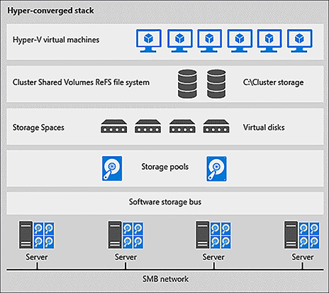
A hyper-converged S2D cluster can either be deployed to bare metal or can be configured on an existing Hyper-V cluster. Enabling S2D on a cluster in VMM automatically installs the File Server and Failover Clustering roles, as well as enables Storage Replica and Data Deduplication. Available storage is automatically captured by the S2D cluster and configured optimally for caching and performance.
1. Create the cluster.
A. In Fabric > Storage click Create, and select Hyper-V Cluster.
B. Select the Enable Storage Spaces Direct option on the General Configuration page (Figure 3-2).
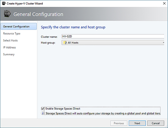
C. Select the hosts and IP addresses to use for the cluster, and click Finish.
2. Configure networking for the cluster using Switch Embedded Teaming on RDMA capable NICs as outlined in Chapter 2. Create two host virtual network adapters attached to non-routable segregated networks for SMB3 communication.
NEED MORE REVIEW? Hyper-Converged S2D
To read more about implementing a hyper-converged S2D architecture in VMM, see https://docs.microsoft.com/en-us/system-center/vmm/s2d-hyper-converged.
Implement Storage Spaces Direct in a disaggregated scenario using VMM
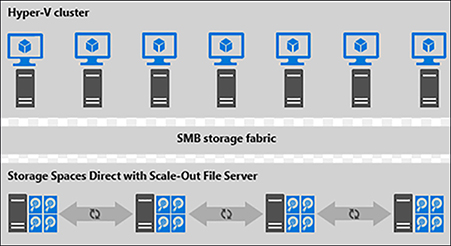
A disaggregated implementation of S2D segments the storage role to a dedicated Scale-out File Server (SOFS) cluster rather than utilizing local disks in the Hyper-V nodes. The compute nodes access VM data via SMB3 file share stored on CSV. Multiple compute clusters can also share the same storage cluster (Figure 3-3).
![]() Exam Tip
Exam Tip
Compute and storage for a cluster are scaled independently in a disaggregated S2D deployment .
A disaggregated SOFS cluster with S2D enabled can either be created by VMM, or you can add an existing cluster that has been deployed outside of VMM. When creating a SOFS cluster, VMM automatically installs the File Server and Failover Clustering roles, as well as enables Storage Replica and Data Deduplication. Available storage is automatically captured by the S2D cluster and configured optimally for caching and performance. Once the cluster is added, you can manage the pool, create file shares, and allocate storage to compute nodes.
1. Create a SOFS cluster.
A. In Fabric> Storage click Create, and select File Server Cluster.
B. Specify a name for the cluster, a name for the SOFS endpoint, and the cluster IP address. In Storage Configuration, select Storage attached directly to each cluster node (Storage Spaces Direct) to create an S2D cluster (Figure 3-4).

C. Select the nodes to add to the cluster, and click Finish.
2. Configure networking for the cluster using RDMA capable NICs as outlined in Chapter 2. Each RDMA capable NIC should be attached to non-routable segregated networks for SMB3 communication.
3. Assign a storage classification to the storage pool, create a file share, and allocate the storage to the Hyper-V cluster as outlined later in this chapter.
MORE INFO: Data Deduplication For Vdi Deployments
Data Deduplication is a Server 2016 feature that can greatly reduce the consumption of storage for workloads that have large amounts of identical data. VDI deployments are ideal for Data Deduplication as the operating system disks attached to virtual machines are usually the same across all VMs. Enabling Data Deduplication on a volume that hosts these files can reduce storage utilization and boost performance in boot-storm scenarios.
Data Deduplication is not compatible with all features of Storage Spaces. For instance, Data Deduplication requires NTFS-formatted volumes and only works with single-tier virtual disks. It’s important to weigh the tradeoffs of enabling Data Deduplication for VDI deployments.
To read more about Data Deduplication in Server 2016, see https://docs.microsoft.com/en-us/windows-server/storage/data-deduplication/overview.
NEED MORE REVIEW? Disaggregated S2D
To read more about implementing a disaggregated S2D architecture in VMM, see https://docs.microsoft.com/en-us/system-center/vmm/s2d-disaggregated.
Implement storage tiering
Storage Spaces supports storage tiering, which enables you to create a single volume with space allocated from multiple media types. This ensures maximum performance by pushing writes to a faster tier of hard disk and eventually moving them to a slower tier. Tiers can consist of NVMe, SSD, and HDD storage types. In S2D, there are three default tiers:
![]() Storage Bus Cache This is the fastest performance tier usually consisting of NVMe.
Storage Bus Cache This is the fastest performance tier usually consisting of NVMe.
![]() Performance This is the next fastest performance tier usually consisting of SSD.
Performance This is the next fastest performance tier usually consisting of SSD.
![]() Capacity This is the lowest performance tier usually consisting of HDD.
Capacity This is the lowest performance tier usually consisting of HDD.
![]() Exam Tip
Exam Tip
S2D automatically uses the fastest media for cache – NVME if available, otherwise SSD.
S2D automatically assigns disks to the appropriate tier based on the type of drives in each system. For instance, if only one type of drive is detected, all storage is added to the Capacity tier. Hybrid configurations using any combination of drives are supported.
Furthermore, each virtual disk that is created in the storage pool can have different amounts of storage from each tier. You can create volumes that have storage from all three tiers, or volumes with different performance expectations using storage from different tiers. For example, you may create a volume for performance sensitive workloads that use storage only in the Performance tier while creating another volume for general-purpose workloads that use storage from the Performance and Capacity tiers.
![]() Quick check
Quick check
You need to create a virtual disk that supports a note change general purpose VM workloads. How should you configure tiering for the volume?
![]() Quick check answer
Quick check answer
You should deploy a virtual disk that uses the space from the Performance and Capacity tier. The Performance tier should make up 10% of the total capacity of the volume. The number of physical disks in the Performance tier should be half the number of disks in the Capacity tier (1:2 ratio).
When enabling S2D via VMM or the Enable-ClusterS2D cmdlet, S2D optimally assigns drives to performance tiers and configure caching for the pool. Caching for solid state media is configured for writes only, whereas the cache for spinning disks handles both reads and writes. This can be modified or configured manually by specifying the CacheDeviceModel parameter and adjusting the CacheModeHDD and CacheModeSSD settings.
Enable-ClusterS2D -CacheDeviceModel “CONTOSO NVME-1520”
Set-ClusterS2D -CacheModeSSD ReadWrite
NEED MORE REVIEW? S2D Tiering
To read more about storage tiers in S2D, see https://docs.microsoft.com/en-us/windows-server/storage/storage-spaces/choosing-drives.
To read more about caching in S2D, see https://docs.microsoft.com/en-us/windows-server/storage/storage-spaces/understand-the-cache.
Implement iSCSI storage
iSCSI is a protocol that enables you to attach block storage from a remote storage system over a standard TCP/IP network. An iSCSI connection consists of a target and an initiator. The iSCSI target is the storage device with the raw block storage, and an iSCSI initiator is the host system mounting the block storage. Windows Server 2016 provides both an iSCSI initiator and an iSCSI target server.
![]() Exam Tip
Exam Tip
iSCSI is popular in environments where shared access to raw storage is necessary using standard Ethernet adapters.
To add an iSCSI SMI-S storage device in VMM:
1. If required, install the provider on a gateway server per the vendor’s instructions.
2. In Fabric > Storage > Storage Providers click Add > Storage Devices.
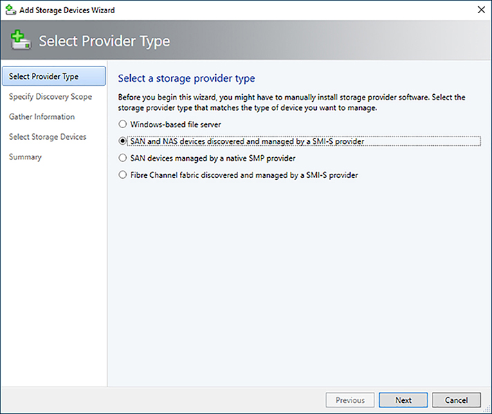
3. Select SAN and NAS devices discovered and managed by a SMI-S provider, and click Next (Figure 3-5).
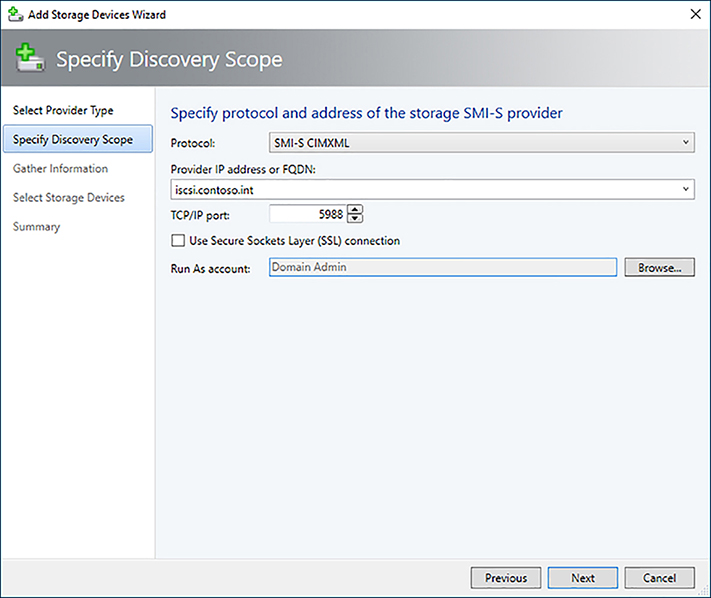
4. Select the protocol type, enter the FQDN or IP address of the iSCSI target, and the Run As account with local administrative privileges on the cluster nodes, then click Next (Figure 3-6).
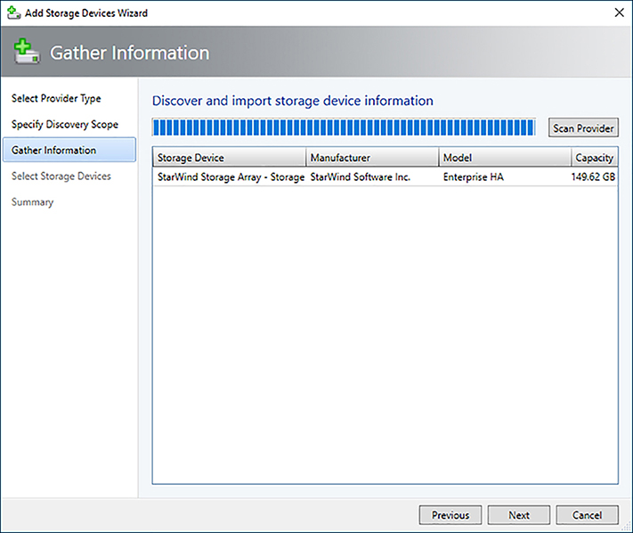
5. On the Discover and import storage device information page, click Next (Figure 3-7).
6. Select the storage pools to bring under VMM management, and assign a storage classification. Click Next (Figure 3-8).

7. Review the summary page, and click Finish.
To use Windows Server 2016 as an iSCSI target:
1. Install the iSCSI Target role on the storage server using the Install-WindowsFeature cmdlet:
Install-WindowsFeature FS-iSCSITarget-Server
2. Create a virtual disk to use with the iSCSI target:
New-Volume -StoragePoolFriendlyName S2D* -FriendlyName “iscsi-storage-host” -
ResiliencySettingName Mirror -Size 100GB -FileSystem NTFS
3. Create a highly available iSCSI target on the cluster:
Add-ClusteriSCSITargetServerRole -Name iscsi -Storage “Cluster Disk 2”
4. Create an account with local administrative privileges and add it as a Run As account in VMM.
5. Add the storage device in VMM.
A. In Fabric > Storage > Storage Providers click Add > Storage Devices.
B. Select SAN and NAS devices discovered and managed by a SMI-S provider, and click Next.
C. Select SMI-S WMI as the protocol type, enter the FQDN of the highly available iSCSI target in the cluster, and the Run As account with local administrative privileges on the cluster nodes, then click Next.
D. On the Discover and import storage device information page, click Next.
E. Assign a storage classification to the storage pools as necessary, click Next.
F. Review the summary page, and click Finish.
NEED MORE REVIEW? Iscsi Storage
To read more about iSCSI storage in VMM, see https://docs.microsoft.com/en-us/system-center/vmm/storage-iscsi.
Implement Storage Spaces fault tolerance
Storage Spaces natively provides for fault tolerance of virtual disks created in the storage pool via the resiliency settings. You can control how data is written to the physical storage by using a combination of the resiliency, physical disk redundancy, and fault domain settings.
![]() Exam Tip
Exam Tip
The physical disk redundancy setting is also referred to as the number of data copies.
The main configuration setting enabling fault tolerance is the resiliency setting. Using this in combination with the physical disk redundancy setting determines the number of fault domains required to support the storage. Storage Spaces supports four levels of resiliency:
![]() Two-way mirror A two-way mirror writes two copies of the data across fault domains and requires 2x the space on the physical storage for the virtual disk.
Two-way mirror A two-way mirror writes two copies of the data across fault domains and requires 2x the space on the physical storage for the virtual disk.
![]() Three-way mirror A three-way mirror writes three copies of the data across fault domains and requires 3x the space on the physical storage for the virtual disk.
Three-way mirror A three-way mirror writes three copies of the data across fault domains and requires 3x the space on the physical storage for the virtual disk.
![]() Single parity Single parity works much like RAID-5 in that data is written across at least two fault domains with a parity bit written in the third fault domain, enabling repair in the event of data loss. The amount of space required varies depending on the number of fault domains.
Single parity Single parity works much like RAID-5 in that data is written across at least two fault domains with a parity bit written in the third fault domain, enabling repair in the event of data loss. The amount of space required varies depending on the number of fault domains.
![]() Dual parity Dual parity works much like RAID-6 in that data is written across at least two fault domains with two parity bits written across two additional fault domains. This provides the same resiliency of a three-way mirror, but with better space efficiency. The amount of space required also varies depending on the number of fault domains.
Dual parity Dual parity works much like RAID-6 in that data is written across at least two fault domains with two parity bits written across two additional fault domains. This provides the same resiliency of a three-way mirror, but with better space efficiency. The amount of space required also varies depending on the number of fault domains.
S2D also supports mixed resiliency where tiers of a volume have different resiliency settings.
A fault domain determines placement of virtual disk data to ensure availability in the event a storage component becomes unavailable. In order to ensure fault tolerance, it’s critical that the fault domain is configured appropriately. This distributes data to physical disks across nodes in the S2D cluster ensuring availability in the event of a device failure. The cluster automatically detects node fault domains corresponding to each node in the cluster. You can configure additional fault domains at the chassis, rack, and site levels using PowerShell cmdlets. These cmdlets support location and description metadata that can be useful in health monitoring.
New-ClusterFaultDomain -FaultDomainType Chassis -Name “Enclosure1” -Location “Rack Unit 20”
New-ClusterFaultDomain -FaultDomainType Rack -Name “Rack1” -Location “NYC01-BLD1”
New-ClusterFaultDomain -FaultDomainType Site -Name “NYC” -Location “CONTOSO HQ NYC”
Set-ClusterFaultDomain -Name “fs01.contoso.int” -Parent “Enclosure1”
Set-ClusterFaultDomain -Name “Enclsoure1” -Parent “Rack1”
Set-ClusterFaultDomain -Name “Rack1” -Parent “NYC”
The storage pool and virtual disks can also be configured with fault domain awareness ensuring data is written across the appropriate fault domains for the volume. If the value is not specified during creation, the virtual disk inherits the storage pool’s FaultDomainAwarenessDefault setting.
![]() Exam Tip
Exam Tip
By default, S2D configures a fault domain awareness of StorageScaleUnit, which is a cluster node.
![]() PhyiscalDisk Data is written to different physical disks without regard for how the disk is connected to the cluster. This setting only provides redundancy in the event of a single disk failure.
PhyiscalDisk Data is written to different physical disks without regard for how the disk is connected to the cluster. This setting only provides redundancy in the event of a single disk failure.
![]() StorageScaleUnit This is the default setting in S2D and refers to a cluster node. Data is written across nodes in the cluster ensuring availability in the event a node becomes unavailable.
StorageScaleUnit This is the default setting in S2D and refers to a cluster node. Data is written across nodes in the cluster ensuring availability in the event a node becomes unavailable.
![]() StorageChassis This ensures data is written to nodes in different chassis.
StorageChassis This ensures data is written to nodes in different chassis.
![]() StorageEnclosure For configurations with multiple disk enclosures attached to a node, this ensures data is written to disks in different enclosures. This is used in legacy SAS JBOD configurations.
StorageEnclosure For configurations with multiple disk enclosures attached to a node, this ensures data is written to disks in different enclosures. This is used in legacy SAS JBOD configurations.
![]() StorageRack This ensures data is written to nodes in different racks.
StorageRack This ensures data is written to nodes in different racks.
NEED MORE REVIEW? Storage Spaces Fault Tolerance
To read more about fault tolerance in S2D, see https://docs.microsoft.com/en-us/windows-server/storage/storage-spaces/storage-spaces-fault-tolerance.
Implement CSVs
The Cluster Shared Volume (CSV) was first introduced in Server 2008 R2 as a way to enable simultaneous read-write access to shared block storage for all nodes in a Hyper-V cluster. This greatly simplifies storage configuration because the virtual hard disks for Hyper-V VMs can be stored on a volume accessible to all nodes via a local path. When configured appropriately, CSV allows each host node direct access to the underlying storage for the workload, while ensuring access to the data in the event of an interruption in the connectivity to the block storage via I/O redirection.
In a hyper-converged S2D scenario, a CSV is created on the cluster and exposed to all Hyper-V host nodes. In a disaggregated S2d scenario, a CSV is created on the storage cluster and a SOFS file share is created on the CSV, which is allocated to the Hyper-V host nodes. CSVs can also be used when block storage is presented to all Hyper-V nodes in a cluster, or with other clustered configurations of Storage Spaces.
![]() Exam Tip
Exam Tip
NTFS is the recommended file system for CSVs, except when using S2D where ReFS is recommended.
1. In Fabric > Servers, right-click the cluster and select Properties.
2. Select Shared Volumes, and click the Add button.
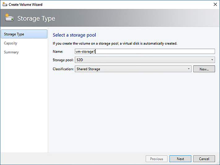
3. Specify a name for the volume, and select the storage pool and classification. Click Next (Figure 3-9).
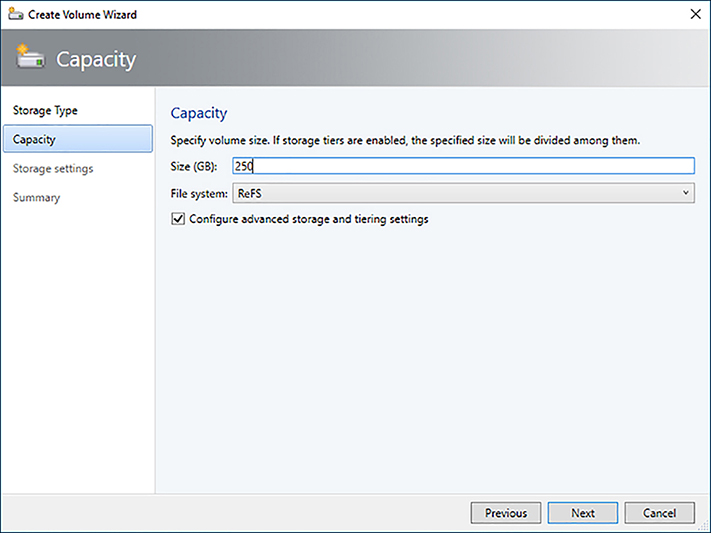
4. Configure a size for the volume, select ReFS as the File System, and select the Configure advanced storage and tiering settings check box (Figure 3-10).
5. Configure the storage tiers as appropriate for the volume (Figure 3-11).

NEED MORE REVIEW? Create Volumes In S2D
To read more about creating volumes in S2D, see https://docs.microsoft.com/en-us/windows-server/storage/storage-spaces/create-volumes.
Determine usage scenarios and requirements for SMB3 storage
SMB3 is the backbone of storage communication for CSVs, file shares, S2D deployments, live migrations, and storage replica. The features of SMB3, like SMB Multichannel and SMB Direct, ensure a resilient, high-throughput, low-overhead connection for storage traffic.
![]() Hyper-V hosts use SMB3 to communicate with SOFS hosts that contain file shares for virtual machines.
Hyper-V hosts use SMB3 to communicate with SOFS hosts that contain file shares for virtual machines.
![]() Clusters leveraging CSV use SMB3 for internal communication between nodes for storage traffic.
Clusters leveraging CSV use SMB3 for internal communication between nodes for storage traffic.
![]() Live Migration of a VM workload between hosts uses SMB3.
Live Migration of a VM workload between hosts uses SMB3.
![]() S2D deployments use SMB3 for internode communication.
S2D deployments use SMB3 for internode communication.
![]() Storage Replica uses SMB3 for communication between clusters.
Storage Replica uses SMB3 for communication between clusters.
Proper sizing and configuration of the network to support the features of SMB3 is necessary to maximize performance and ensure availability in the event of maintenance or failure of a component.
![]() A minimum of four nodes is required for production S2D deployments.
A minimum of four nodes is required for production S2D deployments.
![]() A minimum of two 10Gbps network adapters connected to segmented, non-routable networks is recommended.
A minimum of two 10Gbps network adapters connected to segmented, non-routable networks is recommended.
![]() RDMA capable network adapters (iWARP or RoCE) are required for SMB Direct.
RDMA capable network adapters (iWARP or RoCE) are required for SMB Direct.
![]() Deploy network QoS policies to properly classify storage traffic.
Deploy network QoS policies to properly classify storage traffic.
![]() Enable jumbo frames on storage networks to reduce processing overhead.
Enable jumbo frames on storage networks to reduce processing overhead.
![]() Use ReFS filesystem for S2D, and NTFS for all other CSV types.
Use ReFS filesystem for S2D, and NTFS for all other CSV types.
![]() Exam Tip
Exam Tip
Windows Server 2016 introduces simplified configuration of SMB Multichannel and multi-NIC cluster networks with automatic recognition of IPv6 Link Local networks.
![]() Quick check
Quick check
You are tasked with designing an environment for a new private cloud. You have some general information about the storage requirements, but they will change over time. What’s the best configuration to use to support these workloads?
![]() Quick check answer
Quick check answer
Because the storage requirements will change over time, you should implement a disaggregated Storage Spaces Direct configuration using SMB3 and Storage Tiering. Leveraging a disaggregated deployment ensures you can scale storage and compute tiers individually. SMB3 provides scalable access to the remote storage and Storage Tiering will ensure the platform can absorb spikes in storage traffic.
Configure and enable NIC offload technologies for use as part of storage infrastructure
The SMB3 protocol includes several features that increase the performance and resiliency of storage connections, most notably SMB Direct and SMB Multichannel. Windows Server 2016 automatically configures necessary offload technologies on host NICs to take advantage of these technologies. These features are enabled by default in Windows Server 2016.
![]() SMB Direct This is a feature that improves the throughput and latency of storage connections while lowering CPU utilization. Windows Server 2016 automatically enables SMB Direct on RDMA capable network adapters and is compatible with the Switch Embedded Teaming (SET) virtual switch.
SMB Direct This is a feature that improves the throughput and latency of storage connections while lowering CPU utilization. Windows Server 2016 automatically enables SMB Direct on RDMA capable network adapters and is compatible with the Switch Embedded Teaming (SET) virtual switch.
![]() SMB Multichannel This allows a storage session to use multiple network connections to increase throughput and provide fault tolerance for the storage session. Windows Server 2016 automatically enables SMB Multichannel and establishes multiple sessions based on capabilities of the network adapters. You can also control which adapters are used for SMB Multichannel by managed SMB Multichannel Constraints via PowerShell.
SMB Multichannel This allows a storage session to use multiple network connections to increase throughput and provide fault tolerance for the storage session. Windows Server 2016 automatically enables SMB Multichannel and establishes multiple sessions based on capabilities of the network adapters. You can also control which adapters are used for SMB Multichannel by managed SMB Multichannel Constraints via PowerShell.
Implement SMB file storage
In a disaggregated deployment of S2D, the Hyper-V hosts communicate with the storage cluster via SMB3 file shares. The storage cluster is configured as a Scale-out File Server (SOFS) with S2D enabled. A file share is then created on the S2D storage pool and allocated to the Hyper-V nodes. Once the share has been created, you can assign it to Hyper-V hosts and clusters to be used for placement. You can configure resiliency and tiering settings for the file share at the time of creation.
![]() Exam Tip
Exam Tip
When creating a file share, VMM automatically creates a CSV for the share with a volume using appropriate redundancy settings based on the pool configuration.
1. In Fabric > Storage > File Servers, right-click the SOFS cluster, and select Create File Share.
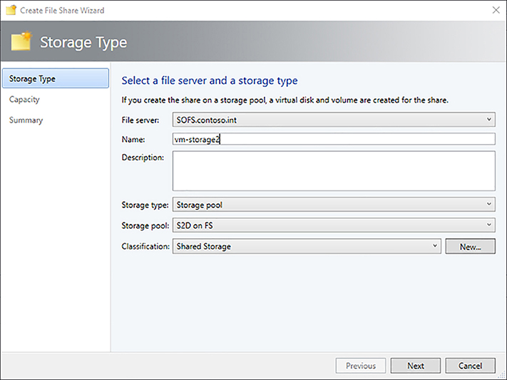
2. Give the share a name, select the S2D storage pool, and assign a classification. Click Next (Figure 3-12).
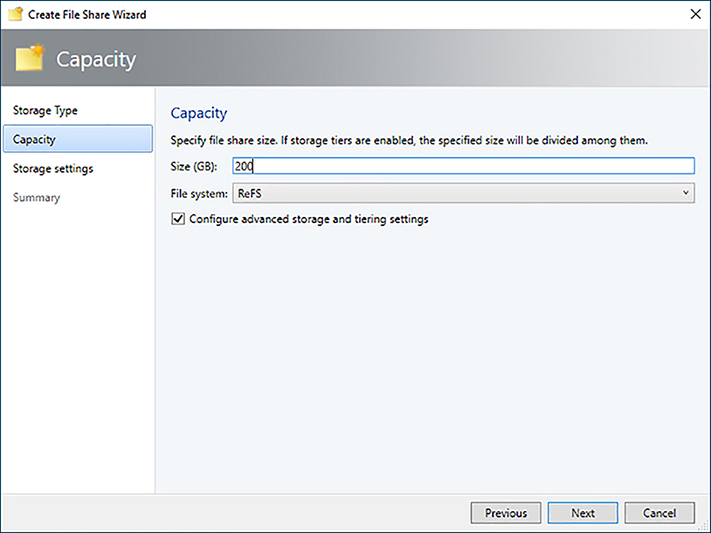
3. Specify a size for the file share, select ReFS as the file system type, and check the box, Configure advanced storage and tiering settings. Click Next (Figure 3-13).
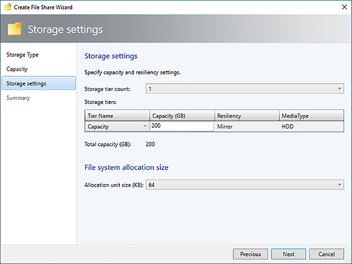
4. Configure tiering for the file share, and click Next (Figure 3-14).
5. Review the settings on the summary screen, and click Finish.
NEED MORE REVIEW? Sofs In Vmm
To read more about deploying a SOFS cluster in VMM, see https://docs.microsoft.com/en-us/system-center/vmm/sofs.
Encrypt cluster volumes
Windows Server 2016 supports the use of BitLocker to encrypt CSVs in a failover cluster. BitLocker relies on an Active Directory based protector to store keys for CSVs. You can encrypt any type of volume presented to the cluster, including S2D virtual disks. Enabling BitLocker on a CSV protects the volume from unauthorized access by encrypting the data on the volume. It does not enable BitLocker inside any guest VMs stored on the volume.
![]() Exam Tip
Exam Tip
A Windows Server 2012 domain controller in the same site as the cluster is required.
Follow these steps to encrypt a CSV:
1. Add the BitLocker Drive Encryption feature using PowerShell on each cluster node (this requires a reboot).
Install-WindowsFeature Bitlocker
2. Turn on maintenance mode for the CSV.
Get-ClusterSharedVolume | Suspend-ClusterResource
3. Enable BitLocker on the CSV owner node.
$secureString = ConvertTo-SecureString “<Plain Text Password>” -AsPlainText Force
Enable-BitLocker C:ClusterStorageVolume1 -PasswordProtector -Password
$secureString
4. Add an ADAccountOrGroup protector using the Cluster Name Object (CNO) to the volume.
Add-BitLockerKeyProtector C:ClusterStorageVolume1 -ADAccountOrGroupProtector -
ADAccountOrGroup CLUSTER$
5. After encryption is completed, turn off maintenance mode.
Get-ClusterSharedVolume | Resume-ClusterResource
NEED MORE REVIEW? Encrypt Cluster Volumes
To read more about protecting clustered volumes with Bitlocker, see https://docs.microsoft.com/en-us/windows/device-security/bitlocker/protecting-cluster-shared-volumes-and-storage-area-networks-with-bitlocker.
Implement Storage QoS policies
Storage QoS policies provide a mechanism to monitor and manage storage performance for VMs. These policies can be configured to guarantee performance for critical workloads and prevent runaway workloads from impacting neighbors. Storage QoS policies work with both hyper-converged deployments using CSV and for deployments where Hyper-V hosts access storage via SOFS. A new role known as a Policy Manager is deployed as part of the File Server cluster. As Hyper-V hosts launch virtual machines, they register with the Policy Manager, which monitors performance and in turn configures Hyper-V with appropriate limits or reservations.
Storage QoS policies can be configured with minimum and maximum normalized IOP limits, as well as maximum allowed bandwidth. Because requests can vary in size, a normalized IOP threshold is configured on the policy. Any IO that is the threshold size or smaller is treated as a single normalized IO, while larger operations are broken into multiple normalized IOs. For example, if the normalized IO threshold is 8KB, a 64K request would represent eight normalized IOPs.
Storage QoS policies can be broken into two categories: Aggregated and Dedicated. The amount of performance allocated to a particular VM varies for each type of policy.
![]() Aggregated Previously known as SingleInstance, this type of policy applies IOP and bandwidth settings across all disks combined. The limits are a shared maximum and minimum across all virtual hard disks. This is useful when reserving or limiting performance for a specific tenant. For example, if you create an Aggregated policy with a maximum of 500 IOPs that is assigned to five virtual hard disks with similar workloads, each virtual hard disk gets about 100 IOPs. If one virtual hard disk is more active than others, it receives a larger share up to the combined limit of 500 across all disks.
Aggregated Previously known as SingleInstance, this type of policy applies IOP and bandwidth settings across all disks combined. The limits are a shared maximum and minimum across all virtual hard disks. This is useful when reserving or limiting performance for a specific tenant. For example, if you create an Aggregated policy with a maximum of 500 IOPs that is assigned to five virtual hard disks with similar workloads, each virtual hard disk gets about 100 IOPs. If one virtual hard disk is more active than others, it receives a larger share up to the combined limit of 500 across all disks.
![]() Dedicated Previously known as MultiInstance, this type of policy applies IOP and bandwidth settings individually to each disk. This is useful when each virtual hard disk or VM has a guaranteed SLA. For example, if you create a Dedicated policy with a maximum of 500 IOPs that is assigned to five virtual hard disks with similar workloads, each virtual hard disk gets 500 IOPs, assuming the backend storage can support the combined workload of 2500 IOPs.
Dedicated Previously known as MultiInstance, this type of policy applies IOP and bandwidth settings individually to each disk. This is useful when each virtual hard disk or VM has a guaranteed SLA. For example, if you create a Dedicated policy with a maximum of 500 IOPs that is assigned to five virtual hard disks with similar workloads, each virtual hard disk gets 500 IOPs, assuming the backend storage can support the combined workload of 2500 IOPs.
![]() Quick check
Quick check
You are designing storage for a cloud environment and need to guarantee IOPs for each workload. Should you use an Aggregated or Dedicated Storage QoS Policy?
![]() Quick check answer
Quick check answer
You should use a Dedicated Storage QoS Policy to guarantee a specific number of IOPs for each VM.
In VMM, the policy type of a Storage QoS policy corresponds to Aggregated and Dedicated Storage QoS policies. To create an Aggregated policy, select All virtual disk instances share resources as the policy type. To create a Dedicated policy, select Resources allocated to each virtual disk instance as the policy type (Figure 3-15).

1. In Fabric > Storage > QoS policies, click Create Storage QoS Policy.
2. Assign a name and description to the policy, and click Next.
3. In the Policy Settings page, specify the policy type, minimum and maximum IOPs, and maximum bandwidth for the policy. Click Next (Figure 3-16).

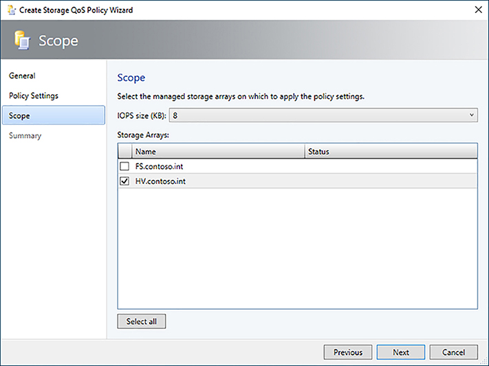
4. Select the storage array to apply the policy to, and click Next (Figure 3-17).
5. Review the settings on the summary screen, and click Finish.
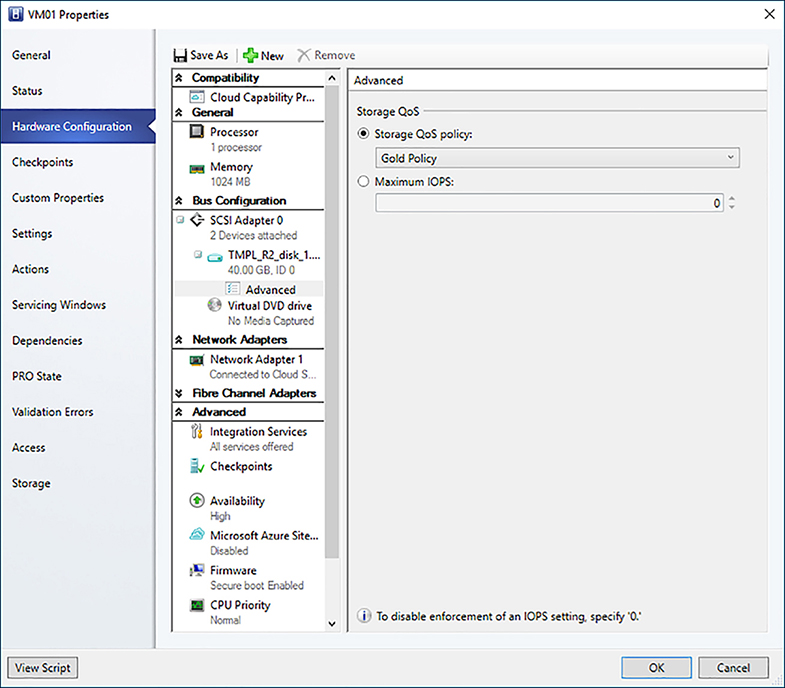
6. Assign the policy by modifying the Advanced Settings of a virtual hard disk
(Figure 3-18).
NEED MORE REVIEW? Storage Qos
To read more about storage QoS in Windows Server 2016, see https://docs.microsoft.com/en-us/windows-server/storage/storage-qos/storage-qos-overview.
Provision thin and thick storage solutions
Virtual hard disks used to abstract storage attached to virtual machines in Hyper-V support multiple types of provisioning. Storage utilization and performance considerations need to be taken into account when selecting the type of storage to use for a workload.
![]() Fixed A fixed size VHD/VHDX allocates the entire size of the disk to a virtual hard disk file at creation time.
Fixed A fixed size VHD/VHDX allocates the entire size of the disk to a virtual hard disk file at creation time.
![]() Dynamic A dynamically expanding VHD/VHDX grows the virtual hard disk file as data is written to the virtual hard disk.
Dynamic A dynamically expanding VHD/VHDX grows the virtual hard disk file as data is written to the virtual hard disk.
![]() Differencing A differencing VHD/VHDX has a parent virtual hard disk and stores only changed blocks from the parent in its virtual hard disk file.
Differencing A differencing VHD/VHDX has a parent virtual hard disk and stores only changed blocks from the parent in its virtual hard disk file.
When using a VHD, a fixed disk is recommended for best performance. When using a VHDX, a dynamic disk is recommended because it has similar performance characteristics to a fixed disk in addition to space savings. The default and recommended type of disk when provisioning a virtual machine in VMM is dynamic.
VMM also supports creating a thin-provisioned storage LUN. Like a dynamic disk, a thin-provisioned storage LUN only allocates storage from the storage pool as data is written to the LUN. In order to implement a thin-provisioned LUN, the storage array must support thin provisioning and a storage administrator must enable thin-provisioning on the storage pool.
Allocate storage array to a host group
Once storage is brought under management in VMM and associated with a storage classification, you can allocate a storage pool or individual LUNs to host groups. Allocating storage pools allows to you assign LUNs to hosts and enables rapid provisioning via SAN copy where LUNs are created as part of the deployment process. After a storage pool is allocated to a host group you must add the iSCSI array to the host nodes in order to allocate LUNs. Once the hosts establish a connection to the array, existing LUNs can be allocated.
1. Ensure the iSCSI initiator service is running and that multipath IO has been installed on the Hyper-V host nodes.
2. In Fabric < Storage click Allocate Capacity.
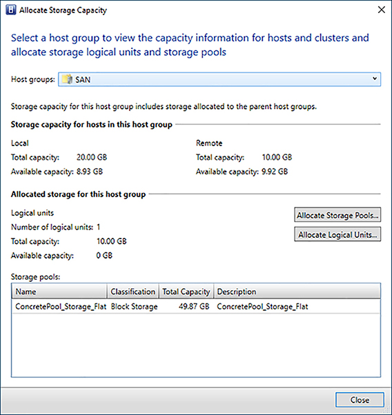
3. Select the host group, and click Allocate Storage Pools (Figure 3-19).
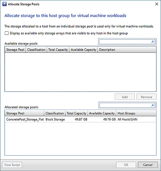
4. Select an available storage pool, and click Add. Then click OK and Close (Figure 3-20).
5. In Fabric > Servers right-click a host node in the cluster, and click Properties.
6. On the Storage tab, click Add, and select Add iSCSI Array.
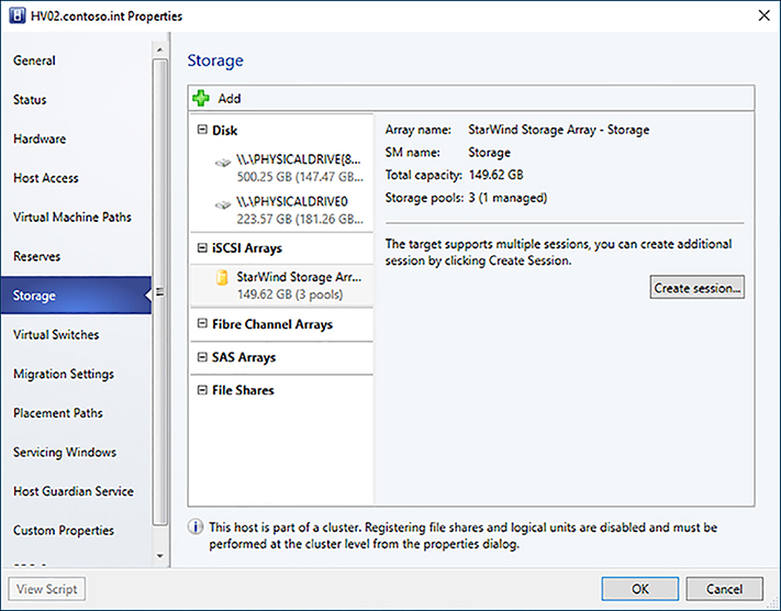
7. Select the storage array that contains the storage pool allocated to the host group where the Hyper-V host resides, and click Create (Figure 3-21).

8. Confirm the host establishes a session to the storage array. If the target supports multiple sessions, click the Create Session button to create additional connections. Click OK (Figure 3-22).
9. In Fabric > Storage click Allocate Capacity.
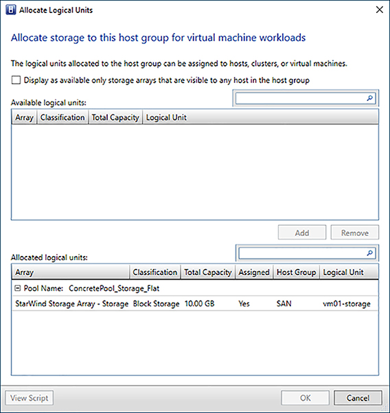
10. Select the host group, and click the Allocate Logical Units button.
11. Select an available LUN for the storage pool, and click Add to allocate it to the hosts in the host group. Click OK and Close (Figure 3-23).
NEED MORE REVIEW? Allocate Storage
To read more about allocating storage to host groups in VMM, see https://docs.microsoft.com/en-us/system-center/vmm/storage-host-group.
Create a LUN for a Hyper-V cluster from allocated storage
If a storage pool has been allocated to a host group that contains Hyper-V hosts or clusters, you can create and assign LUNs directly from the properties window of the node. This simplifies the process of configuring storage because VMM manages connections to the storage array. Multipath IO is required on the host and you must ensure that the host has established the necessary sessions with the storage array.
When assigning LUNs, VMM creates one storage group per host or cluster node on the storage array. In some cases, you may need to use a single storage group for a cluster. To enable this, set the CreateStorageGroupsPerCluster property to $true using the Set-SCStorageArray cmdlet.
1. In Fabric > Servers right-click the Hyper-V cluster, and click Properties.
2. In the Available Storage tab click the Add button.
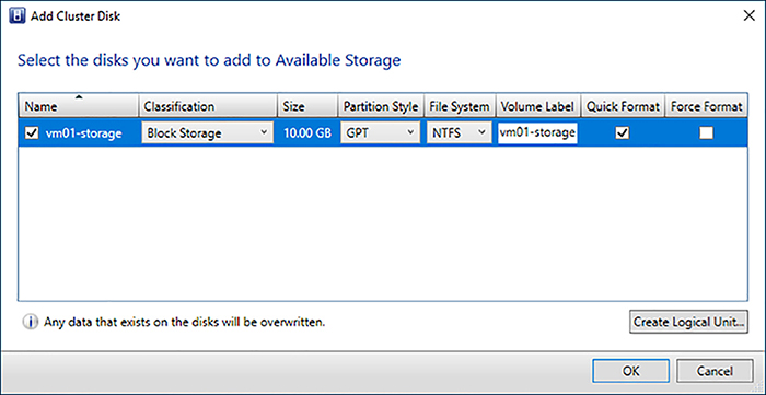
3. On the Add Cluster Disk screen, click the Create Logical Unit button.
4. Select the storage pool allocated to the Hyper-V cluster, enter a name for the LUN, and specify the size. Click OK to create the LUN (Figure 3-24).

5. Select the LUN, assign a volume label, enable Quick Format, and click OK, and then click OK again (Figure 3-25).
6. The disk is added to the cluster as available storage, which can be selected when deploying a VM. The LUN is automatically allocated to the VM during deployment (Figure 3-26).

NEED MORE REVIEW? Supported Storage Arrays
To read more about supported storage arrays in VMM, see https://docs.microsoft.com/en-us/system-center/vmm/supported-arrays.
Allocate file share to a Hyper-V cluster
File shares are allocated to Hyper-V clusters to allow placement of VMs. Assigning a file share automatically configures the share and NTFS permissions allowing Hyper-V hosts in the cluster appropriate access to the share. The Host Access account used by the cluster must have local administrator permissions on each node of the file server cluster.
1. Confirm the Run As account.
A. In Fabric > Servers right-click the cluster, and select Properties.
B. Confirm the Run As account configured for the Cluster Management Credentials has appropriate permissions on the file server cluster nodes.
2. Add the file share to the cluster.
A. In Fabric > Servers right-click the cluster, and select Properties.
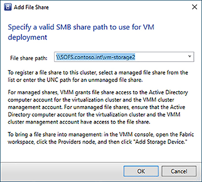
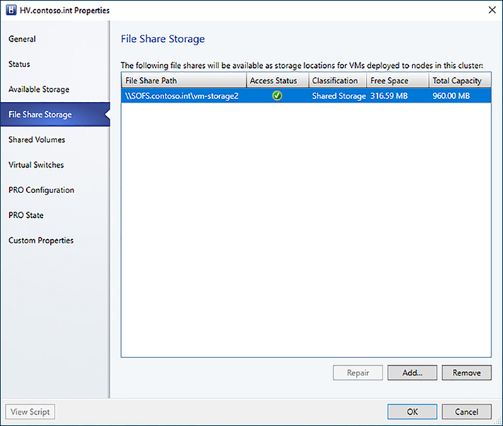
B. Under File Share Storage, click Add. Select the managed file share path from the drop-down, and click OK (Figure 3-27).
C. After the job has completed, you can confirm that VMM was able to configure permissions appropriately by reviewing the Access Status column for the file share in the cluster properties (Figure 3-28).
NEED MORE REVIEW? File Shares In Vmm
To read more about assigning file shares in VMM, see https://docs.microsoft.com/en-us/system-center/vmm/storage-file#assign-files-shares.
Implement storage classifications for storage pools
Storage classifications are abstractions for storage devices in VMM. You can group storage with similar capabilities and/or performance by assigning the same storage classification. A storage classification can then be assigned to hosts, clusters, templates, and devices rather than a specific storage device. VMM automatically recognizes two types of storage classifications:
![]() Local Storage Local storage is any storage directly attached to a host, typically via a RAID controller or SAS JBOD.
Local Storage Local storage is any storage directly attached to a host, typically via a RAID controller or SAS JBOD.
![]() Remote Storage Remote storage is any storage not directly attached to a host, typically via a SMB3 file share.
Remote Storage Remote storage is any storage not directly attached to a host, typically via a SMB3 file share.
You can create any number of storage classifications that can be assigned to a pool of storage. Storage from different devices and clusters can be assigned the same classification. For example, you could define a classification called Shared Storage that is assigned to storage devices in two different locations as a way of treating the storage as equivalent. Follow these steps to assign a storage classification to a storage pool:
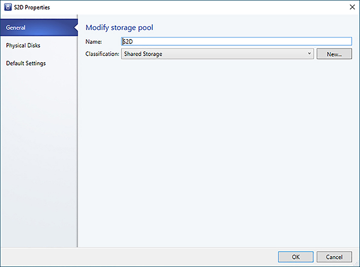
1. In Fabric > Storage > Arrays right-click the cluster, and select Manage Pools.
2. Select the pool that was created, and click Edit.
3. Update the storage classification, and click OK (Figure 3-29).
NEED MORE REVIEW? Storage Classifications
To read more about storage classifications in VMM, see https://docs.microsoft.com/en-us/system-center/vmm/storage-classification.
Skill 3.2 Manage Software-Defined Storage
Software-Defined Storage enables new ways for managing VM data. Traditionally, storage environments and replication technologies had dedicated hardware and administrators in order to achieve maximize performance, capacity, and availability. VMM enables cloud administrators to fully manage storage solutions including deploying disaster recovery solutions, optimizing storage configuration, and managing storage as part of the VM lifecycle. Windows Server and System Center 2016 can take advantage of enhanced storage array capabilities like Offloaded Data Transfer, replication, and rapid provisioning.
This skill covers how to:
![]() Implement Storage Replica solutions
Implement Storage Replica solutions
![]() Implement Hyper-V replica solutions
Implement Hyper-V replica solutions
![]() Integrate Hyper-V Replica with Azure Site Recovery (ASR) for secondary on-
Integrate Hyper-V Replica with Azure Site Recovery (ASR) for secondary on-
premises site
![]() Implement Offloaded Data Transfer (ODX)
Implement Offloaded Data Transfer (ODX)
![]() Determine LUN usage
Determine LUN usage
![]() Decommission storage from a Hyper-V Host
Decommission storage from a Hyper-V Host
![]() Optimize Storage Spaces Direct storage pools
Optimize Storage Spaces Direct storage pools
![]() Implement Network QoS policies to control RDMA and SMB storage connections
Implement Network QoS policies to control RDMA and SMB storage connections
![]() Implement SAN Copy to rapidly provision VMs
Implement SAN Copy to rapidly provision VMs
Implement Storage Replica solutions
Storage Replica is a new feature of Windows Server and System Center 2016 Datacenter edition that enables storage-agnostic, block-level, synchronous replication between clusters for disaster recovery or for stretching a failover cluster across sites. This helps eliminate the cost and complexity of hardware replication technologies while still providing zero data loss protection across any storage vendor. Storage Replica uses the SMB3 protocol to exchange data creating a resilient, high-throughput connection.
![]() Exam Tip
Exam Tip
Synchronous storage replication requires sufficient network throughput and a maximum latency of 5ms.
In order to use Storage Replica with VMM, the deployment must meet the following criteria:
![]() You must use Datacenter edition of Windows Server and System Center 2016.
You must use Datacenter edition of Windows Server and System Center 2016.
![]() The storage in both clusters must be of the same type (file or volume).
The storage in both clusters must be of the same type (file or volume).
![]() Source and destination volumes must be the same size.
Source and destination volumes must be the same size.
![]() The same VMM server must manage source and destination storage.
The same VMM server must manage source and destination storage.
![]() Source and destination storage must be assigned the same storage classification.
Source and destination storage must be assigned the same storage classification.
![]() You must use synchronous replication.
You must use synchronous replication.
![]() You must use PowerShell to configure Storage Replica.
You must use PowerShell to configure Storage Replica.
![]() Exam Tip
Exam Tip
File servers for Storage Replica communicate using ICMP, SMB (tcp/445 and tcp/5545), and WS-MAN(tcp/5985).
1. Pair the storage arrays.
$array1 = Get-SCStorageArray -Name “Primary Array”
$array2 = Get-SCStorageArray -Name “Secondary Array”
$pool1 = Get-SCStoragePool | ? StorageArray -eq $array1 | ? Name -match “Pool 1”
$pool2 = Get-SCStoragePool | ? StorageArray -eq $array2 | ? Name -match “Pool 2”
Set-SCStorageArray -Pair -StorageArray $array1 -PeerStorageArray $array2.Name
2. Provision the LUNs and create the storage groups.
$vol1data = New-SCStorageVolume -StorageArray $array1 -StoragePool $pool1 -Name
“vol1_data” -SizeInBytes $vol1dataSize -RunAsynchronously -PhysicalDiskRedundancy
2 -FileSystem CSVFS_NTFS -GuidPartitionTable
$vol1log = New-SCStorageVolume -StorageArray $array1 -StoragePool $pool1 -Name
“vol1_log” -SizeInBytes $vol1logSize -RunAsynchronously -PhysicalDiskRedundancy 2
-FileSystem NTFS -GuidPartitionTable
$vol1 = New-SCReplicationGroup -CreateOnArray -Name “vol1” -StorageVolume
$vol1data -LogStorageVolume $vol1log
$vol2data = New-SCStorageVolume -StorageArray $array2 -StoragePool $pool2 -Name
“vol2_data” -SizeInBytes $vol2dataSize -RunAsynchronously -PhysicalDiskRedundancy
2 -FileSystem CSVFS_NTFS -GuidPartitionTable
$vol2log = New-SCStorageVolume -StorageArray $array2 -StoragePool $pool2 -Name
“vol2_log” -SizeInBytes $vol2logSize -RunAsynchronously -PhysicalDiskRedundancy 2
-FileSystem NTFS -GuidPartitionTable
$vol2 = New-SCReplicationGroup -CreateOnArray -Name “vol2” -StorageVolume
$vol2data -LogStorageVolume $vol2log
3. Enable replication on the primary storage group.
Set-SCReplicationGroup -ReplicationGroup $vol1 -Operation EnableProtection -
TargetReplicationGroup $vol2 -EnableProtectionMode Synchronous
4. Refresh the storage providers.
Read-SCStorageProvider -StorageProvider $array1.StorageProvider
Read-SCStorageProvider -StorageProvider $array2.StorageProvider
5. Verify the replication status.
Get-SCReplicationGroup | ft Name, IsPrimary, ReplicationState, ReplicationHealth
NEED MORE REVIEW? Storage Replica
To read more about Storage Replica in VMM, see https://docs.microsoft.com/en-us/system-center/vmm/storage-replica.
Implement Hyper-V replica solutions
Hyper-V Replica is a feature of Hyper-V that allows replication of virtual machines on a Hyper-V host or cluster to another Hyper-V host or cluster for disaster recovery purposes. Once initialized, Hyper-V Replica uses change tracking to ship only the changes to a virtual hard disk to the secondary site, reducing bandwidth utilization. You can also customize the replication frequency and the number of recovery points to store for the replicated virtual machine. Lastly, Hyper-V Replica enables you to execute Test, Planned and Unplanned failovers of virtual machines.
Hyper-V Replica can be configured between two Hyper-V hosts using Hyper-V Manager settings. When configuring replication using a Hyper-V cluster, the Hyper-V Replica Broker cluster role must be configured. The Hyper-V Replica Broker acts as a single replication endpoint for the secondary site and manages settings related to secondary site configuration for all nodes in the cluster.
Configuration of Hyper-V Replica requires appropriate authentication of inbound traffic. Hyper-V Replica supports both Kerberos and certificate-based authentication. If using certificate-based authentication, you need to deploy a certificate for the replication endpoint that is trusted on each node in the remote cluster. The certificate must include both client and server extensions for enhanced key usage, and the subject common name must be the FQDN of the host or Hyper-V Replica Broker.
![]() Exam Tip
Exam Tip
If using Kerberos authentication, data is not encrypted between source and destination hosts.
![]() Quick check
Quick check
You are designing a disaster recovery architecture in which the workload requires zero data loss. Which replication technology should you chose?
![]() Quick check answer
Quick check answer
You should use Storage Replica because it supports synchronous replication. Hyper-V Replica supports a RPO as low as five seconds.
Follow these steps to implement Hyper-V Replica between host clusters:
1. Deploy the Hyper-V Replica Broker using PowerShell.
Add-ClusterServerRole -Name “HVR-Broker” -StaticAddress 10.184.108.100
Add-ClusterResource -Name “Virtual Machine Replication Broker” -Type “Virtual
Machine Replication Broker” -Group “HVR-Broker”
Add-ClusterResourceDependency “Virtual Machine Replication Broker” “HVR-Broker”
Start-ClusterGroup “HVR-Broker”
2. Configure the Hyper-V Replica Broker role.
A. In Failover Cluster Manager, connect to the cluster, and click Roles.
B. Select the Hyper-V Replica Broker group, and then click the Resources tab in the Details pane.
C. Right-click the Hyper-V Replica Broker role and select Replication Settings.
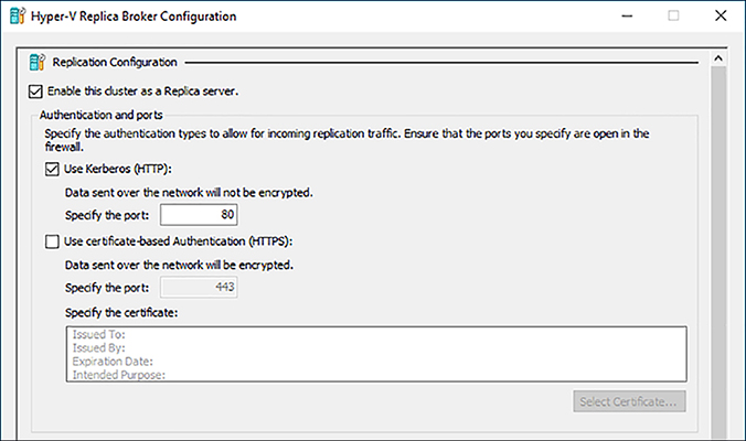
D. Select the check box to enable the cluster as a replica server and choose the authentication mechanism (Figure 3-30).
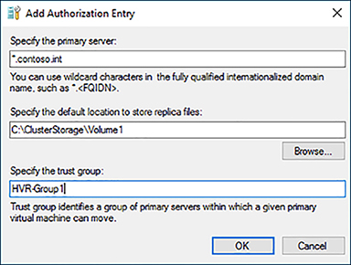
E. Select the Allow replication from the specified servers radio button and click Add. Enter the FQDN of the secondary endpoint, location for replica files, and a trust group for the endpoint (Figure 3-31).
![]() Exam Tip
Exam Tip
The storage location for replication configuration files must be a CSV or file share.
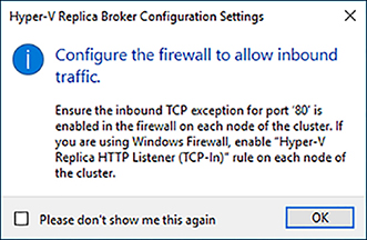
F. Enable the appropriate firewall rules on the Hyper-V hosts in the cluster (Figure 3-32).
3. Enable replication for a virtual machine using PowerShell.
Enable-VMReplication -VMName “VM01” -ReplicaServerName “HVR-Broker.contoso.int”
-ReplicaServerPort 80 -AuthenticationType Kerberos
NEED MORE REVIEW? Hyper-V Replica
To read more about deploying Hyper-V Replica, see https://docs.microsoft.com/en-us/windows-server/virtualization/hyper-v/manage/set-up-hyper-v-replica.
Integrate Hyper-V Replica with Azure Site Recovery (ASR) for secondary on-premises site
Azure Site Recovery (ASR) is a cloud-based solution that integrates with VMM and Hyper-V Replica enabling recovery to Azure or to a secondary on-premises site. VMM requires the use of ASR when replicating between sites or between on-premises and Azure.
![]() Exam Tip
Exam Tip
ASR also supports using SAN replication between sites for supported storage arrays.
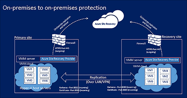
When using ASR to replicate between sites, Azure acts as the orchestration mechanism between the sites – no VM data is transmitted to the public cloud. Enabling replication and performing failover operations can be initiated from both the Azure portal as well as the VMM console. ASR supports the creation of recovery plans that help automate the process of recovery by orchestrating the order in which VMs are restored on the secondary site as well as automation of any customization necessary after failover.
![]() Exam Tip
Exam Tip
ASR for VMM supports RPOs of 30 seconds, 5 minutes, or 15 minutes.
ASR uses a Recovery Vault in Azure to store replication configuration settings. A VMM cloud is the logical entity that is registered to a Recovery Vault in Azure. Replication of Hyper-V VMs with VMM via ASR can replicate between clouds on two VMM servers, or between clouds on a single VMM server. Equivalent VM Networks should be configured on both VMM servers to allow for network mapping (Figure 3-33).
![]() Exam Tip
Exam Tip
ASR supports offline initial replication of VM data.
Follow these general guidelines when configuring ASR to replication Hyper-V VMs to a secondary site with VMM.
1. Create a Recovery Vault in Azure.
2. Install the Azure Site Recovery Provider on each VMM server.
3. Register the VMM Servers to the Recovery Vault using the vault registration key.
4. Configure the replication policy.
5. Configure network and storage mapping.
6. Apply the replication policy to the VMs in the VMM cloud.
NEED MORE REVIEW? Asr Replication
To read more about replicating Hyper-V VMs in VMM clouds to a secondary site using ASR, see https://docs.microsoft.com/en-us/azure/site-recovery/site-recovery-vmm-to-vmm.
To read more about configuring secondary site replication with ASR via SAN, see https://docs.microsoft.com/en-us/azure/site-recovery/site-recovery-vmm-san.
Implement Offloaded Data Transfer (ODX)
Offloaded Data Transfer (ODX) enables direct transfer within or between compatible storage arrays without transmitting data to the host, thereby reducing resource utilization and maximizing throughput. ODX transfers are transparent to the Windows operating system. ODX uses a token mechanism representing the data being transferred instead of reading or writing data via the hosts. ODX can be used for storage migration or for deploying VMs from a library server to a host.
In VMM, data can be transferred between hosts or between library servers and hosts in one of two ways: Background Intelligent Transfer System (BITS) or Fast File Copy (FFC). VMM relies on the FFC feature of Windows to implement ODX. In order to implement FFC in VMM, you need a storage array that supports ODX and to associate a management Run As account to the Library Server and Hyper-V hosts. FFC automatically attempts to use ODX before falling back to a network transfer.
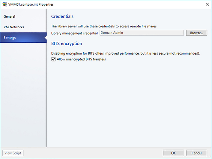
1. In Library > Library Servers right-click the library server, and select Properties.
2. On the settings tab, configure an appropriate Library Management Credential (Figure 3-34).
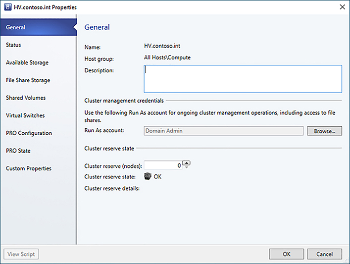
3. In Fabric > Servers, right-click the Hyper-V cluster, and select Properties.
4. On the General tab, configure an appropriate Cluster management credential
(Figure 3-35).
NEED MORE REVIEW? Odx
To read more about deploying ODX, see https://technet.microsoft.com/en-us/library/jj200627.
Determine LUN usage
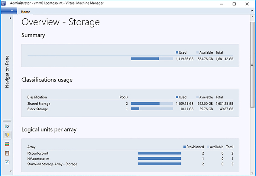
VMM provides insight into the utilization of LUNs for storage arrays and storage pools that are under VMM management. You can easily see summary information of LUN allocation as well as detailed assignment and utilization of LUNs.
![]() To view a summary report of storage, click Fabric > Storage > Classifications and Pools. Select Show > Overview from the ribbon (Figure 3-36).
To view a summary report of storage, click Fabric > Storage > Classifications and Pools. Select Show > Overview from the ribbon (Figure 3-36).
![]() To review a detailed report of LUN assignment and utilization, click Fabric > Storage > Classifications and Pools. Select Show > Hosts/Clusters from the ribbon (Figure 3-37).
To review a detailed report of LUN assignment and utilization, click Fabric > Storage > Classifications and Pools. Select Show > Hosts/Clusters from the ribbon (Figure 3-37).

Decommission storage from a Hyper-V Host
LUNs that have been created or are managed by VMM can also be deleted directly from VMM. The LUN must not be in use by a virtual machine and must first be disassociated from the Hyper-V host before it can be deleted. This simplifies the process of managing the lifecycle of storage because a cloud administrator can perform these functions without having to involve a storage administrator.
1. In Fabric > Servers, right-click the cluster, and select Properties.
2. On the Available Storage tab find the LUN you want to decommission, and click Remove, and then click OK.
3. In Fabric > Storage > Classification and Pools, expand the storage classification assigned to the storage pool where the LUN resides.
4. Right-click the LUN and select Remove, and then click OK.
File Shares can also be decommissioned from Hyper-V hosts. Again, the share must not be in use by any virtual machines and must be disassociated from the Hyper-V host before it can be deleted.
1. In Fabric > Servers, right-click the cluster, and select Properties.
2. On the File Share Storage tab find the share you want to decommission and click Remove, and then click OK.
3. In Fabric > Storage > File Shares, expand the SOFS server where the share resides.
4. Right-click the share, and select Remove.
5. Select the check box to also delete the File System in the pool that supports this file share option, and then click OK.
NEED MORE REVIEW? Decomission Storage
To read more about removing storage LUNs in VMM, see https://technet.microsoft.com/en-us/library/hh362418(v=sc.12).aspx.
Optimize Storage Spaces Direct storage pools
As disks are added or removed from an S2D pool, the amount of data that resides on each of the physical disks can become uneven. This can result in certain physical disks becoming full, causing writes to fail before a virtual disk is full. As new storage is added to the pool, optimizing existing data is necessary to take advantage of the additional disks for read operations to improve performance.
You can optimize the storage pool using the following PowerShell cmdlet:
Optimize-StoragePool S2D*
NEED MORE REVIEW? S2D OPTIMIZATION
To read more about optimizing S2D pools, see https://docs.microsoft.com/en-us/windows-server/storage/storage-spaces/storage-spaces-optimize-pool.
Implement Network QoS policies to control RDMA and SMB storage connections
Network QoS policies can ensure storage connections are given priority when RDMA capable network adapters are used in a Switched Embedded Teaming (SET) virtual switch. This is implemented via Data Center Bridging (DCB) in Windows Server 2016, which allows for a converged network fabric.
Follow these steps to configure a Network QoS policy for SMB Direct:
1. Turn on DCB.
Install-WindowsFeature Data-Center-Bridging
2. Configure a policy for SMB traffic.
New-NetQoSPolicy “SMB” -NetDirectPortMatchCondition 445 -PriorityValue8021Action 3
3. Turn on flow control for SMB.
Enable-NetQoSFlowControl -Priority 3
Disable-NetQoSFlowControl -Priority 0,1,2,4,5,6,7
4. Guarantee a percentage of bandwidth for SMB traffic.
New-NetQoSTrafficClass “SMB” -Priority 3 -BandwidthPercentage 30 -Algorithm ETS
5. Apply the policy to the network adapters.
Enable-NetAdapterQos -InterfaceAlias “Ethernet 1”
Enable-NetAdapterQoS -InterfaceAlias “Ethernet 2”
NEED MORE REVIEW? Smb Direct
To read more about deploying SMB Direct with RDMA adapters, see https://technet.microsoft.com/en-us/library/dn583822(v=ws.11).aspx.
Implement SAN Copy to rapidly provision VMs
SAN Copy is a method of rapidly provisioning virtual machines using storage array capabilities to clone LUNs for new VMs. When using SAN copy to provision a new VM, a command is issued to the storage array to clone the LUN where the template is stored, which is then attached to the Hyper-V host. There are several requirements to implement SAN Copy.
![]() The storage array must support cloning or snapshots and the feature must be enabled.
The storage array must support cloning or snapshots and the feature must be enabled.
![]() The storage array must be managed by VMM via SMI-S and the provider must support the SAN copy feature.
The storage array must be managed by VMM via SMI-S and the provider must support the SAN copy feature.
![]() The library server must also be a Hyper-V host and must be in the same host group as the destination Hyper-V hosts.
The library server must also be a Hyper-V host and must be in the same host group as the destination Hyper-V hosts.
![]() The storage pool must be assigned to the host group containing the Hyper-V hosts.
The storage pool must be assigned to the host group containing the Hyper-V hosts.
![]() All hosts must use the same type of SAN connectivity.
All hosts must use the same type of SAN connectivity.
![]() Multipath IO must be enabled on each host and the storage array.
Multipath IO must be enabled on each host and the storage array.
To create a SAN Copy capable template, create a virtual machine template as outlined in Chapter 4. On the Select Library Server tab, ensure the transfer type column is set to SAN, which ensures that the template has detected the storage is attached to a storage array that is SAN Copy enabled.
To deploy a SAN Copy capable template, deploy a virtual machine from the SAN Copy capable template as outlined in Chapter 4. Ensure that you select a host that has access to the storage pool where the LUN associated to the template resides and that Transfer the virtual hard disk by using the SAN is selected on the Configure Settings tab under Deployment options.
![]() Quick check
Quick check
You are designing storage for a private cloud that will leverage existing SAN investments. What features of Software Defined Storage should you consider implementing?
![]() Quick check answer
Quick check answer
You should consider implementing ODX, SAN Copy and SAN Replication for ASR. These features take advantage of the advanced functionality of storage arrays.
NEED MORE REVIEW? San Copy
To read more about deploying VMs using SAN copy in VMM, see https://docs.microsoft.com/en-us/system-center/vmm/vm-san-copy.
Thought experiment
In this thought experiment, demonstrate your skills and knowledge of the topics covered in this chapter. You can find the answer to this thought experiment in the next section.
You are a systems engineer for Contoso, Ltd, a premier provider of managed technology strategy, configuration, and customization consulting services. A new enterprise client has asked for your assistance in designing a storage solution for their hosted private cloud environment with the following requirements:
1. Need to keep costs low and wish to avoid using expensive SAN technologies.
2. Must be able to scale storage without having to add compute nodes.
3. Some workloads have latency sensitive storage IO requirements and they need to ensure they receive sufficient performance.
4. Sensitive data will be stored on VMs and they need to ensure it is sufficiently protected.
5. Need a design that provides for disaster recovery in the event of a failure of the primary site. They also need to perform DR test drills on a periodic basis.
Thought experiment answers
This section provides the solutions for the tasks included in the thought experiment.
1. You should implement a Storage Spaces Direct (S2D) solution. S2D uses commodity hardware to create a resilient, scalable Software-Defined Storage solution at a lower cost by using local drives instead of SAN. Because it supports caching and tiering, storage can be designed to meet necessary performance requirements.
2. You should implement a disaggregated S2D deployment. Dedicated cluster nodes provide storage to compute nodes allowing you to scale storage by adding nodes to the storage cluster without having to add compute nodes.
3. To guarantee performance for latency sensitive workloads, you should implement storage tiering using an NVMe cache. Additionally, you should configure dedicated Storage QoS policies to guarantee a sufficient number of IOPs and throughput for critical workloads.
4. To protect data stored on the storage cluster, you should enable BitLocker for the CSV that hosts the file share for VM data. BitLocker encrypts the volume ensuring that data is only accessible to the storage cluster. In the event disks are removed or retired from the storage cluster, BitLocker encryption ensures that the data cannot be recovered without the encryption key.
5. You should use ASR to configure replication between VMM servers in a primary site and secondary site. Additionally, you can use Storage Replica to replicate the CSV hosting VM data from the S2D cluster in the primary site to a S2D cluster in the secondary site. ASR can orchestrate the disaster recovery failover plan and enables simplified testing of that recovery plan.
Chapter summary
![]() S2D is a new feature of Windows Server 2016 that allows you to create highly available and highly scalable storage using commodity hardware. S2D supports tiering using any type of local disk including NVMe, SSD, and HDD. You can deploy S2D in a hyper-converged deployment where each Hyper-V host’s local storage is pooled, or you can deploy S2D in a disaggregated deployment where a dedicated SOFS cluster contains the storage pool.
S2D is a new feature of Windows Server 2016 that allows you to create highly available and highly scalable storage using commodity hardware. S2D supports tiering using any type of local disk including NVMe, SSD, and HDD. You can deploy S2D in a hyper-converged deployment where each Hyper-V host’s local storage is pooled, or you can deploy S2D in a disaggregated deployment where a dedicated SOFS cluster contains the storage pool.
![]() Resiliency can be defined per virtual disk and can take into account physical datacenter layout. The default configuration of S2D ensures that data is written across cluster nodes, but can be adjusted to account for blade servers and external factors by writing data across racks.
Resiliency can be defined per virtual disk and can take into account physical datacenter layout. The default configuration of S2D ensures that data is written across cluster nodes, but can be adjusted to account for blade servers and external factors by writing data across racks.
![]() VMM can deploy and manage many types of storage including S2D, SOFS, SAN, NAS iSCSI and Fibre Channel. Storage arrays can be brought under management of VMM, which simplifies storage provisioning and management. Storage Pools can be allocated to host groups allowing automated provisioning and deprovisioning of LUNS.
VMM can deploy and manage many types of storage including S2D, SOFS, SAN, NAS iSCSI and Fibre Channel. Storage arrays can be brought under management of VMM, which simplifies storage provisioning and management. Storage Pools can be allocated to host groups allowing automated provisioning and deprovisioning of LUNS.
![]() Storage Replica is a new feature of Windows Server 2016 that enables you to perform block-level, synchronous replication at a cluster volume level. This allows for replication between dissimilar storage devices and can be managed by VMM.
Storage Replica is a new feature of Windows Server 2016 that enables you to perform block-level, synchronous replication at a cluster volume level. This allows for replication between dissimilar storage devices and can be managed by VMM.
![]() SMB3 is the heart of storage communication. RDMA-capable network adapters are needed to maximum performance and minimize latency for storage traffic and inter-cluster communication.
SMB3 is the heart of storage communication. RDMA-capable network adapters are needed to maximum performance and minimize latency for storage traffic and inter-cluster communication.
![]() Storage QoS policies provide reservations and limits for virtual workloads to both guarantee performance and limit utilization. Policies can be applied to individual virtual hard disks or aggregated across tiers.
Storage QoS policies provide reservations and limits for virtual workloads to both guarantee performance and limit utilization. Policies can be applied to individual virtual hard disks or aggregated across tiers.
![]() BitLocker supports encryption of CSV volumes protecting cluster disks for unauthorized access outside of the cluster. The BitLocker key is stored in Active Directory and requires a domain controller of Windows Server 2012 or higher.
BitLocker supports encryption of CSV volumes protecting cluster disks for unauthorized access outside of the cluster. The BitLocker key is stored in Active Directory and requires a domain controller of Windows Server 2012 or higher.
![]() VMM can take advantage of advanced SAN technologies like ODX and SAN Copy. These features must be enabled on the storage array by the storage administrator.
VMM can take advantage of advanced SAN technologies like ODX and SAN Copy. These features must be enabled on the storage array by the storage administrator.