Chapter 2
Implement platform protection
One of the main aspects of cloud computing is the shared responsibility model, where the cloud solution provider (CSP) and the customer share different levels of responsibilities, depending on the cloud service category. When it comes to platform security, Infrastructure as a Service (IaaS), customers will have a long list of responsibilities. However, in a Platform as a Service (PaaS) scenario, there are still some platform security responsibilities; they are not as extensive as when using IaaS workloads.
Azure has native platform security capabilities and services that should be leveraged to provide the necessary level of security for your IaaS and PaaS workloads while maintaining a secure management layer.
Skills in this chapter:
Skill 2.1: Implement advanced network security
To implement an Azure network infrastructure, you need to understand the different connectivity options available in Azure. These options will enable you to implement a variety of scenarios with different requirements. This section of the chapter covers the skills necessary to implement advanced network security.
Overview of Azure network components
Azure networking provides built-in capabilities to enable connectivity between Azure resources, connectivity from on-premises networks to Azure resources, and branch office to branch office connectivity in Azure.
While those skills are not directly called out in the AZ-500 exam outline, it is important for you to understand these concepts. If you’re already comfortable with your skill level, you can skip to “Secure the connectivity of virtual networks,” later in this chapter.
To better understand the different components of an Azure network, let’s review Contoso’s architecture diagram shown in Figure 2-1.

FIGURE 2-1 Contoso network diagram
In Figure 2-1, you can see Azure infrastructure (on top), with three virtual networks. Contoso needs to segment its Azure network in different virtual networks (VNets) to provide better isolation and security. Having VNets in its Azure infrastructure allows Contoso to connect Azure Virtual Machines (VMs) to securely communicate with each other, the Internet, and Contoso’s on-premises networks.
A VNet is much like a traditional physical, on-premises network where you operate in your own data center. However, a VNet offers some additional benefits, including scalability, availability, and isolation. When you create a VNet, you must specify a custom private IP address that will be used by the resources that belong to this VNet. For example, if you deploy a VM in a VNet with an address space of 10.0.0.0/24, the VM will be assigned a private IP, such as 10.0.0.10/24.
Notice in Figure 2-1 that there are subnets in each VNet in Contoso’s network. Contoso needs to segment the virtual network into one or more subnetworks and allocate a portion of the virtual network’s address space to each subnet. With this setup, Contoso can deploy Azure resources in a specific subnet, just like it used to do in its on-premises network. From an organizational and structure perspective, subnets have allowed Contoso to segment its VNet address space into smaller segments that are appropriate for its internal network. By using subnets, Contoso also was able to improve address allocation efficiency.
Another important trio of components is shown in Figure 2-1: subnets A1, B1, and C1. Each of these subnets has a network security group (NSG) bound to it, which provides an extra layer of security based on rules that allow or deny inbound or outbound network traffic.
NSG security rules are evaluated by their priority, and each is identified with a number between 100 and 4096, where the lowest numbers are processed first. The security rules use 5-tuple information (source address, source port, destination address, destination port, and protocol) to allow or deny the traffic. When the traffic is evaluated, a flow record is created for existing connections, and the communication is allowed or denied based on the connection state of the flow record. You can compare this type of configuration to the old VLAN segmentation that was often implemented with on-premises networks.
Contoso is headquartered in Dallas, and it has a branch office in Sydney. Contoso needs to provide secure and seamless RDP/SSH connectivity to its virtual machines directly from the Azure portal over TLS. Contoso doesn’t want to use jumpbox VMs and instead wants to allow remote access to back-end subnets through the browser. For this reason, Contoso implemented Azure Bastion, as you can see in the VNet C, subnet C1 in Figure 2-1.
Azure Bastion is a platform-managed PaaS service that can be provisioned in a VNet.
For Contoso’s connectivity with Sydney’s branch office, it is using a VPN gateway in Azure. A virtual network gateway in Azure is composed of two or more VMs that are deployed to a specific subnet called a gateway subnet. The VMs that are part of the virtual network gateway contain routing tables and run specific gateway services. These VMs are automatically created when you create the virtual network gateway, and you don’t have direct access to those VMs to make custom configurations to the operating system.
When planning your VNets, consider that each VNet may only have one virtual network gateway of each type, and the gateway type may only be VPN or ExpressRoute. Use VPN when you need to send encrypted traffic across the public Internet to your on-premises resources.
For example, let’s say that Contoso needs a faster, more reliable, secure, and consistent latency to connect its Azure network to its headquarters in Dallas. Contoso decides to use ExpressRoute, as shown in Figure 2-1. ExpressRoute allows Contoso to extend its on-premises networks into the Microsoft cloud (Azure or Office 365) over a private connection because ExpressRoute does not go over the public Internet.
In Figure 2-1, notice that the ExpressRoute circuit consists of two connections, both of which are Microsoft Enterprise Edge Routers (MSEEs) at an ExpressRoute Location from the connectivity provider or your network edge. While you might choose not to deploy redundant devices or Ethernet circuits at your end, the connectivity providers use redundant devices to ensure that your connections are handed off to Microsoft in a redundant manner. This Layer 3 connectivity redundancy is a requirement for Microsoft SLA to be valid.
Network segmentation is important in many scenarios, and you need to understand the design requirements to suggest the implementation options. Let’s say you want to ensure that Internet hosts cannot communicate with hosts on a back-end subnet but can communicate with hosts on the front-end subnet. In this case, you should create two VNets: one for your front-end resources and another for your back-end resources.
When configuring your virtual network, also take into consideration that the resources you deploy within the virtual network will inherit the capability to communicate with each other. You can also enable virtual networks to connect to each other, or you can enable resources in either virtual network to communicate with each other by using virtual network peering. When connecting virtual networks, you can choose to access other VNets that are in the same or different Azure regions. Follow the steps below to configure your virtual network using the Azure portal:
Navigate to the Azure portal at https://portal.azure.com.
In the search bar, type virtual networks, and under Services, click Virtual Networks. The Virtual Networks page appears, as shown in Figure 2-2.

FIGURE 2-2 Azure Virtual Networks page
Click the Add button, and the Create Virtual Network page appears, as shown in Figure 2-3.
On the Basics tab, select the Subscription for the VNet and the Resource Group.

FIGURE 2-3 The Create Virtual Network page allows you to customize your VNet deployment
In the Name field, type a comprehensive name for the VNet, and in the Region field, select the Azure region in which the VNet is going to reside. Finally, click the IP Addresses tab.
On the IP Addresses page, in the IPv4 field, type the address space in classless inter-domain routing (CIRD) format; for example, you could enter 10.3.0.0/16.
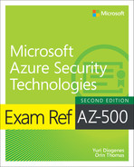
Click the Add Subnet button. The Add Subnet blade appears, as shown in Figure 2-4.
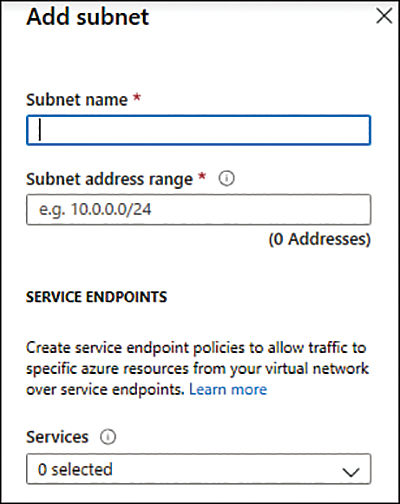
FIGURE 2-4 Add Subnet blade
In the Subnet Name field, type a name for this subnet.
In the Subnet Address Range, type the IP range for this subnet in CIDR format, such as 10.3.0.0/16. Keep in mind that the smallest supported IPv4 subnet is /29, and the largest is /8.
Click the Add button; the subnet that you just created appears under the Subnet Name section.
Leave the default selections for now and click the Review + Create button. The validation result appears, which is similar to the one shown in Figure 2-5.

FIGURE 2-5 Summary of the selections with the validation results
Click the Create button.
The Overview page appears with the
deployment finalstatus. On this page, click the Go To Resource button and review these options on the left navigation pane: Overview, Address Space, and Subnets.
Notice that the parameters you configured during the creation of your VNet will be distributed among the different options on the VNet page. As you saw in the previous steps, creating a VNet using the Azure portal is a straightforward process, though in some circumstances, you might need to automate the creation process, and you can use PowerShell to do just that.
When you are creating your virtual network, you can use any IP range that is part of RFC 1918, which includes
224.0.0.0/4(multicast)255.255.255.255/32(broadcast)127.0.0.0/8(loopback)169.254.0.0/16(link-local)168.63.129.16/32(internal DNS)
Also, consider the following points:
Azure reserves
x.x.x.0as a network address andx.x.x.1as a default gateway.x.x.x.2andx.x.x.3are mapped to the Azure DNS IPs to the VNet space.x.x.x.255is reserved for a network broadcast address.
To automate that, you can either use PowerShell on your client workstation (using Connect-AzAccount to connect to your Azure subscription) or by using Cloud Shell directly from https://shell.azure.com. To create a virtual network using PowerShell, you need to use the New-AzVirtualNetwork cmdlet, as shown here:
$AZ500Subnet = New-AzVirtualNetworkSubnetConfig -Name AZ500Subnet -AddressPrefix
"10.3.0.0/24"
New-AzVirtualNetwork -Name AZ500VirtualNetwork -ResourceGroupName ContosoCST -Location
centralus -AddressPrefix "10.3.0.0/16" -Subnet $AZ500Subnet
In this example, you have the $AZ500Subnet variable, which configures a new subnet for this VNet using the New-AzVirtualNetworkSubnetConfig cmdlet. Next, the New-AzVirtualNetwork cmdlet is used to create the new VNet, and it calls the $AZ500Subnet variable at the end of the command line to create the subnet.
After creating your VNet, you can start connecting resources to it. In an IaaS scenario, it is very common to connect your virtual machines (VMs) to the VNet. Assuming you have Virtual Machine Contributor privileges in the subscription, you can quickly deploy a new VM using the New-AzVM PowerShell cmdlet, as shown here:
New-AzVm '
    -ResourceGroupName "ContosoCST" '
    -Location "East US" '
    -VirtualNetworkName "AZ500VirtualNetwork" '
    -SubnetName "AZ500Subnet" '
    -Name "AZ500VM" '
Routing
In a physical network environment, you usually need to start configuring routes as soon as you expand your network to have multiple subnets. In Azure, the routing table is automatically created for each subnet within an Azure VNet. The default routes created by Azure and assigned to each subnet in a virtual network can’t be removed. The default route that is created contains an address prefix and the next hop (where the package should go). When traffic leaves the subnet, it goes to an IP address within the address prefix of a route; the route that contains the prefix is the route used by Azure.
When you create a VNet, Azure creates a route with an address prefix that corresponds to each address range that you defined within the address space of your VNet. If the VNet has multiple address ranges defined, Azure creates an individual route for each address range. You don’t need to worry about creating routes between subnets within the same VNet because Azure automatically routes traffic between subnets using the routes created for each address range. Also, differently from your physical network topology and routing mechanism, you don’t need to define gateways for Azure to route traffic between subnets. In an Azure routing table, this route appears as:
Source Default
Address prefix Unique to the virtual network
Next hop type Virtual network
If the destination of the traffic is the Internet, Azure leverages the system-default route 0.0.0.0/0 address prefix, which routes traffic for any address not specified by an address range within a virtual network to the Internet. The only exception to this rule is if the destination address is for one of Azure’s services. In this case, instead of routing the traffic to the Internet, Azure routes the traffic directly to the service over Azure’s backbone network. The other scenarios in which Azure will add routes are as follows:
When you create a VNet peering In this case, a route is added for each address range within the address space of each virtual network peering that you created.
When you add a Virtual Network Gateway In this case, one or more routes with a virtual network gateway listed as the next hop type are added.
When a VirtualNetworkServiceEndpoint is added When you enable a service endpoint to publish an Azure service to the Internet, the public IP addresses of the services are added to the route table by Azure.
You might also see None in the routing table’s Next Hop Type column. Traffic routed to this hop is automatically dropped. Azure automatically creates default routes for 10.0.0.0/8, 192.168.0.0/16 (RFC 1918), and 100.64.0.0/10 (RFC 6598).
At this point, you might ask: “If all these routes are created automatically, in which scenario should I create a custom route?” You should do this only when you need to alter the default routing behavior. For example, if you add an Azure Firewall or any other virtual appliance, you can change the default route (0.0.0.0/0) to point to this virtual appliance. This will enable the appliance to inspect the traffic and determine whether to forward or drop the traffic. Another example is when you want to ensure that traffic from hosts doesn’t go to the Internet; you can control the routing rules to accomplish that.
To create a custom route that is effective for your needs, you need to create a custom routing table, create a custom route, and associate the routing table to a subnet, as shown in the PowerShell sequence that follows.
Create the routing table using
New-AzRouteTablecmdlet, as shown here:$routeTableAZ500 = New-AzRouteTable ' -Name 'AZ500RouteTable' ' -ResourceGroupName ContosoCST ' -location EastUS
Create the custom route using multiple cmdlets. First, you retrieve the route table information using
Get-AzRouteTable, and then you create the route usingAdd-AzRouteConfig. Lastly, you use theSet-AzRouteTableto write the routing configuration to the route table:Get-AzRouteTable ' -ResourceGroupName "ContosoCST" ' -Name "AZ500RouteTable" ' | Add-AzRouteConfig ' -Name "ToAZ500Subnet" ' -AddressPrefix 10.0.1.0/24 ' -NextHopType "MyVirtualAppliance" ' -NextHopIpAddress 10.0.2.4 ' | Set-AzRouteTable
Now that you have the routing table and the custom route, you can associate the route table with the subnet. Notice here that you first write the subnet configuration to the VNet using the
Set-AzVirtualNetworkcmd. After that, you useSet-AzVirtualNetworkSubnetConfigto associate the route table to the subnet:$virtualNetwork | Set-AzVirtualNetwork Set-AzVirtualNetworkSubnetConfig ' -VirtualNetwork $virtualNetwork ' -Name 'CustomAZ500Subnet' ' -AddressPrefix 10.0.0.0/24 ' -RouteTable $routeTableAZ500 | ' Set-AzVirtualNetwork
Virtual network peering
When you have multiple VNets in your Azure infrastructure, you can connect those VNets using VNet peering. You can use VNet peering to connect VNets within the same Azure region or across Azure regions; doing so is called global VNet peering.
When the VNets are in the same region, the network latency between VMs that are communicating through the VNet peering is the same as the latency within a single virtual network. It’s also important to mention that the traffic between VMs in peered virtual networks is not through a gateway or over the public Internet; instead, that traffic is routed directly through the Microsoft backbone infrastructure. To create a VNet peering using the Azure portal, follow these steps:
Navigate to the Azure portal at https://portal.azure.com.
In the search bar, type virtual networks, and under Services, click Virtual Networks.
Click the VNet that you want to peer, and on the left navigation pane, click Peerings (see Figure 2-6).
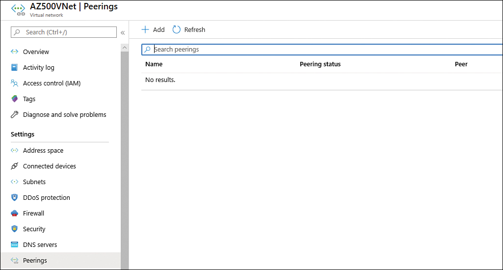
FIGURE 2-6 Configuring VNet peering
Click the Add button, and the Add Peering page appears, as shown in Figure 2-7.
In the Name field, type a name for this peering.
In the Subscription field, select the subscription that has the VNet to which you want to connect.
In the Virtual Network field, click the drop-down menu and select the VNet that you want to peer.
In the Name Of The Peering From Remote Virtual Network field, type the name that you want to appear for this peering connection on the other VNet.
The next two options—Allow Virtual Network Access From [VNet name] To Remote Virtual Network and Allow Virtual Network Access From Remote Virtual To [VNet name]—are used to control the communication between those VNets. If you want full connectivity from both directions, make sure to leave the Enabled option selected (default selection) for both. Enabling communication between virtual networks allows resources connected to either virtual network to communicate with each other with the same bandwidth and latency as if they were connected to the same virtual network.

FIGURE 2-7 Adding a new peering
The next two options—Allow Forwarded Traffic From Remote Virtual Network To [VNet name] and Allow Forwarded Traffic From [VNet name] To Remote Virtual Network—are related to allowing forwarded traffic. You should select Enable for both settings only when you need to allow traffic that didn’t originate from the VNet to be forwarded by a virtual network appliance through a peering. For example, consider three virtual networks named VNetTX, VNetWA, and MainHub. A peering exists between each spoke VNet (VNetTX and VNetWA) and the Hub virtual network, but peerings don’t exist between the spoke VNets. A network virtual appliance is deployed in the Hub VNet, and user-defined routes can be applied to each spoke VNet to route the traffic between the subnets through the network virtual appliance. If this option is disabled, there will be no traffic flow between the two spokes through the hub.
Click OK to finish the configuration.
To configure a VNet peering using PowerShell, you just need to use the Add-AzVirtual NetworkPeering cmdlet, as shown here:
Add-AzVirtualNetworkPeering -Name 'NameOfTheVNetPeering' -VirtualNetwork SourceVNet
-RemoteVirtualNetworkId RemoteVNet
A peered VNet can have its own gateway, and the VNet can use its gateway to connect to an on-premises network. One common use of VNet peering is when you are building a hub-spoke network. In this type of topology, the hub is a VNet that acts as a central hub for connectivity to your on-premises network. The spokes are VNets that are peering with the hub, allowing them to be isolated, which increases their security boundaries. An example of this topology is shown in Figure 2-8.

FIGURE 2-8 Hub-spoke network topology using VNet peering
A hybrid network uses the hub-spoke architecture model to route traffic between Azure VNets and on-premises networks. When there is a site-to-site connection between the Azure VNet and the on-premises data center, you must define a gateway subnet in the Azure VNet. All the traffic from the on-premises data center would then flow via the gateway subnet.
Network address translation
Azure has a Virtual Network NAT (network address translation) capability that enables outbound-only Internet connectivity for virtual networks. This is a common scenario when you want that outbound connectivity to use a specified static public IP address (static NAT), or you want to use a pool of public IP addresses (Dynamic NAT).
Keep in mind that outbound connectivity is possible without the use of an Azure load balancer or a public IP address directly attached to the VM. Figure 2-9 shows an example of the topology with a NAT Gateway.
You can implement NAT by using a public IP prefix directly, or you can distribute the public IP addresses of the prefix across multiple NAT gateway resources. NAT also changes the network route because it takes precedence over other outbound scenarios, and it will replace the default Internet destination of a subnet. From an availability standpoint (which is critical for security), NAT always has multiple fault domains, which means it can sustain multiple failures without service outage.

FIGURE 2-9 NAT Gateway topology
To create a NAT Gateway for your subnet, you first need to create a public IP address and a public IP prefix. Follow the steps below to perform these tasks:
Navigate to the Azure portal at https://portal.azure.com.
In the main dashboard, click the Create A Resource button.
On the New page, type Public IP and click the Public IP Address option that appears in the list.
On the Public IP Address page, click the Create button; the Create Public IP Address page appears, as shown in Figure 2-10.

FIGURE 2-10 Creating a public IP address to be used by NAT Gateway
Type the name for this public IP address and select the subscription, resource group, and the Azure location. For this example, you can leave all other options with their default selections. Once you finish, click the Create button.
Now you should repeat steps 1 and 2. In the third step, type public IP prefix and click the Public IP Prefix option that appears in the drop-down menu.
On the Create A Public IP Prefix page, configure the following relevant options:
Select the appropriate Subscription.
Select the appropriate Resource Group.
Type the Prefix Name.
Select the appropriate Azure Region.
In the Prefix Size drop-down menu, select the appropriate size for your deployment.
Once you finish configuring these options, click the Review + Create button and click Create to finish.
Now that you have the two requirements fulfilled, you can create the NAT Gateway.
Navigate to the Azure portal at https://portal.azure.com.
In the main dashboard, click the Create A Resource button.
On the New page, type NAT Gateway and click the NAT Gateway option in the list.
On the NAT Gateway page, click Create. The Create Network Address Translation (NAT) Gateway page appears, as shown in Figure 2-11.
On the Basics tab, make sure to configure the following options:
Select the appropriate Subscription and Resource Group.
Type the NAT Gateway Name.
Select the appropriate Azure Region and Availability Zone.
Move to the next tab, Outbound IP, and select the Public IP Address and Prefix Name that you created previously.
Next, on the Subnet tab, you will configure which subnets of a VNet should use this NAT gateway.
The Tags tab is optional, and you should use it only when you need to logically organize your resources in a particular taxonomy to easily identify them later.
You can review a summary of the selections in the Review + Create tab. Once you finish reviewing it, click the Create button.
You can also use the New-AzNatGateway cmdlet to create a NAT Gateway using PowerShell, as shown:
New-AzNatGateway -ResourceGroupName "AZ500RG" -Name "nat_gt" -IdleTimeoutInMinutes
4 -Sku "Standard" -Location "eastus2" -PublicIpAddress PublicIPAddressName

FIGURE 2-11 Creating a NAT Gateway in Azure
Secure the connectivity of hybrid networks
With organizations migrating to the cloud, virtual private networks (VPNs) are constantly used to establish a secure communication link between on-premises and cloud network infrastructure. Many organizations will also keep part of their resources on-premises while taking advantage of cloud computing to host different services, which creates a hybrid environment. While this is one common scenario, there are many other scenarios where a VPN can be used. You can use Azure VPN to connect two different Azure regions or subscriptions.
Azure natively offers a service called VPN gateway, which is a specific type of virtual network gateway that is used to send encrypted traffic between an Azure virtual network and on-premises resources. You can also use a VPN gateway to send encrypted traffic between Azure virtual networks. When planning your VPN Gateway implementation, be aware that each virtual network can have only one VPN gateway, and you can create multiple connections to the same VPN gateway. When deploying a hybrid network that needs to create a cross-premises connection, you can select from different types of VPN connectivity. The available options are:
Point-to-Site (P2S) VPN This type of VPN is used in scenarios where you need to connect to your Azure VNet from a remote location. For example, you would use P2S when you are working remotely (hotel, home, conference, and the like), and you need to access resources in your VNet. This VPN uses SSTP (Secure Socket Tunneling Protocol) or IKE v2 and does not require a VPN device.
Site-to-Site (S2S) VPN This type of VPN is used in scenarios where you need to connect on-premises resources to Azure. The encrypted connection tunnel uses IPsec/IKE (IKEv1 or IKEv2).
VNet-to-VNet As the name states, this VPN is used in scenarios where you need to encrypt connectivity between VNets. This type of connection uses IPsec (IKE v1 and IKE v2).
Multi-Site VPN This type of VPN is used in scenarios where you need to expand your site-to-site configuration to allow multiple on-premises sites to access a virtual network.
ExpressRoute is another option that allows connectivity from your on-premises resources to Azure. This option uses a private connection to Azure from your WAN, instead of a VPN connection over the Internet.
VPN authentication
The Azure VPN connection is authenticated when the tunnel is created. Azure generates a pre-shared key (PSK), which is used for authentication. This pre-shared key is an ASCII string character no longer than 128 characters. This authentication happens for policy-based (static routing) or routing-based VPN (dynamic routing). You can view and update the pre-shared key for a connection with these PowerShell cmdlets:
Get-AzVirtualNetworkGatewayConnectionSharedKey This command is used to show the pre-shared key.
Set-AzVirtualNetworkGatewayConnectionSharedKey This command is used to change the pre-shared key to another value.
For point-to-site (P2S) VPN scenarios, you can use native Azure certificate authentication, RADIUS server, or Azure AD authentication. For native Azure certificate authentication, a client certificate is presented on the device, which is used to authenticate the users who are connecting. The certificate can be one that was issued by an enterprise certificate authority (CA), or it can be a self-signed root certificate. For native Azure AD, you can use the native Azure AD credentials. Keep in mind that native Azure AD is only supported for the OpenVPN protocol and Windows 10 (Windows 10 requires the use of the Azure VPN Client).
If your scenario requires the enforcement of a second factor of authentication before access to the resource is granted, you can use Azure Multi-Factor Authentication (MFA) with conditional access. Even if you don’t want to implement MFA across your entire company, you can scope the MFA to be employed only for VPN users using conditional access capability.
Another option available for P2S is the authentication using RADIUS (which also supports IKEv2 and SSTP VPN). Keep in mind that RADIUS is only supported for VpnGw1, VpnGw2, and VpnGw3 SKUs. For more information about the latest VPN SKUs, visit http://aka.ms/az500vpnsku. Figure 2-12 shows an example of the options that appear when you are configuring a P2S VPN, and you need to select the authentication type.

FIGURE 2-12 Authentication options for VPN
The options that appear right under the Authentication Type section will vary according to the Authentication Type you select. In Figure 2-12, Azure Certificate is chosen, and the page shows options to enter the Name and Public Certification Data for the Root Certificates and the Name and Thumbprint for the Revoked Certificates. If you select RADIUS authentication, you will need to specify the Server IP Address and the Server Secret. Lastly, if you select the Azure Active Directory option, you will need to specify the Tenant’s URL; the Audience (which identifies the recipient resource the token is intended for); and the Issuer (which identifies the Security Token Service (STS) that issued the token). Lastly, choose the Azure AD tenant.
Your particular scenario will dictate which option to use. For example, Contoso’s IT department needs to implement a VPN solution that can integrate with a certificate authentication infrastructure that it already has through RADIUS. In this case, you should use RADIUS certificate authentication. When using the RADIUS certificate authentication, the authentication request is forwarded to a RADIUS server, which handles the certificate validation. If the scenario requires that the Azure VPN gateway perform the certificate authentication, the right option would be to use the Azure native certificate authentication.
ExpressRoute encryption
If your connectivity scenario requires a higher level of reliability, faster speeds, consistent latencies, and higher security than typical connections over the Internet, you should use ExpressRoute, which provides layer 3 connectivity between your on-premises network and the Microsoft Cloud.
ExpressRoute supports two different encryption technologies to ensure the confidentiality and integrity of the data that is traversing from on-premises to Microsoft’s network. The options are
Point-to-point encryption by MACsec
End-to-end encryption by IPsec
MACsec encrypts the data at the media access control (MAC) level or at network layer 2. When you enable MACsec, all network control traffic is encrypted, which includes the border gateway protocol (BGP) data traffic and your (customer) data traffic. This means that you can’t encrypt only some of your ExpressRoute circuits.
If you need to encrypt the physical links between your network devices and Microsoft’s network devices when you connect to Microsoft via ExpressRoute Direct, MACsec is preferred. MACsec also allows you to bring your own MACsec key for encryption and store it in Azure Key Vault. If this is the design choice, remember that you will need to decide when to rotate the key.
Keep in mind that when you update the MACsec key, the on-premises resources will temporally lose connectivity to Microsoft over ExpressRoute. This happens because MACsec configuration only supports pre-shared key mode, so you must update the key on both sides. In other words, if there is a mismatch, traffic flow won’t occur. Plan the correct maintenance window to reduce the impact on production environments.
The other option is to use end-to-end encryption with IPsec, which encrypts data at the Internet protocol (IP)–level or at the network layer 3. A very common scenario is to use IPsec to encrypt the end-to-end connection between on-premises resources and your Azure VNet. In a scenario where you need to encrypt layers 2 and 3, you can enable MACsec and IPsec.
Point-to-site
To implement a point-to-site (P2S) VPN in Azure, you first need to decide what authentication method you will use based on the options that were presented earlier in this section. The authentication method will dictate how the P2S VPN will be configured. When configuring the P2S VPN, you will see the options available under Tunnel Type, as shown in Figure 2-13.
FIGURE 2-13 Different options for the VPN tunnel
Another important variable to select is the protocol that will be used. Use Table 2-1 to select the most-appropriate protocol based on the advantages and limitations:
TABLE 2-1 Advantages and limitations
Protocol | Advantages | Limitations |
OpenVPN Protocol | This is a TLS VPN-based solution that can traverse most firewalls on the market. Can be used to connect from a variety of operating systems, including Android, iOS (versions 11.0 and above), Windows, Linux, and Mac devices (OSX versions 10.13 and above). | Basic SKU is not supported. Not available for the classic deployment model. |
Secure Socket Tunneling Protocol (SSTP) | Can traverse most firewalls because it uses TCP port 443. | Only supported on Windows devices. Supports up to 128 concurrent connections, regardless of the gateway SKU. |
IKEv2 | Standard-based IPsec VPN solution. Can be used to connect to Mac devices (OSX versions 10.11 and above). | Basic SKU is not supported. Not available for the classic deployment model. Uses nonstandard UDP ports, so you need to ensure that these ports are not blocked on the user’s firewall. The ports in use are UDP 500 and 4500. |
Site-to-site
A site-to-site (S2S) VPN is used in most scenarios to allow the communication from one location (on-premises) to another (Azure) over the Internet. To configure an S2S, you need the following prerequisites fulfilled before you start:
An on-premises VPN device that is compatible with Azure VPN policy–based configuration or route-based configuration. See the full list at https://aka.ms/az500s2sdevices.
Externally facing public IPv4 address.
IP address range from your on-premises network that will be utilized to allow Azure to route to your on-premises location.
Secure connectivity of virtual networks
Network security groups (NSG) in Azure allow you to filter network traffic by creating rules that allow or deny inbound network traffic to or outbound network traffic from different types of resources. You can think of an NSG as a Virtual LAN or VLAN in a physical network infrastructure. For example, you could configure an NSG to block inbound traffic from the Internet to a specific subnet that only allows traffic from a network virtual appliance (NVA).
Network security groups can be enabled on the subnet or to the network interface in the VM, as shown in Figure 2-14.
In the diagram shown in Figure 2-14, you have two different uses of NSG. In the first case, the NSG is assigned to the subnet A. This can be a good way to secure the entire subnet with a single set of NSG rules. However, there will be scenarios where you might need to control the NSG on the network interface level, which is the case of the second scenario (subnet B), where VM 5 and VM 6 have an NSG assigned to the network interface.
When inbound traffic is coming through the VNet, Azure processes the NSG rules that are associated with the subnet first—if there are any—and then it processes the NSG rules that are associated with the network interface. When the traffic is leaving the VNet (outbound traffic), Azure processes the NSG rules associated with the network interface first, followed by the NSG rules associated with the subnet.
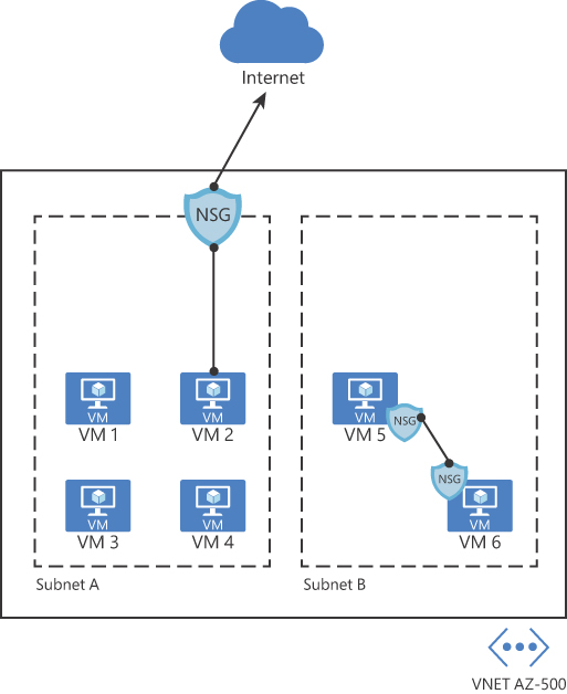
FIGURE 2-14 Different NSG implementations
When you create an NSG, you need to configure a set of rules to harden the traffic. These rules use the following parameters:
Name The name of the rule.
Priority The order in which the rule will be processed. Lower numbers have high priority, which means that a rule priority 100 will be evaluated before rule priority 300. Once the traffic matches the rule, it will stop moving forward to evaluate other rules. When configuring the priority, you can assign a number between 100 and 4096.
Source Define the source IP, CIDR Block, Service Tag, or Application Security Group.
Destination Define the destination IP, CIDR Block, Service Tag, or Application Security Group.
Protocol Define the TCP/IP protocol that will be used, which can be set to TCP, UDP, ICMP, or Any.
Port Range Define the port range or a single port.
Action This determines the action that will be taken once this rule is processed. This can be set to Allow or Deny.
Before creating a new NSG and adding new rules, it is important to know that Azure automatically creates default rules on NSG deployments. Following is a list of the inbound rules that are created:
AllowVNetInBound
Priority 65000
Source VirtualNetwork
Source Ports 0–65535
Destination VirtualNetwork
Destination Ports 0–65535
Protocol Any
Access Allow
AllowAzureLoadBalancerInBound
Priority 65001
Source AzureLoadBalancer
Source Ports 0–65535
Destination 0.0.0.0/0
Destination Ports 0–65535
Protocol Any
Access Allow
DenyAllInbound
Priority 65500
Source 0.0.0.0/0
Source Ports 0–65535
Destination 0.0.0.0/0
Destination Ports 0–65535
Protocol Any
Access Deny
Below is a list of outbound rules that are created:
AllowVNetOutBound
Priority 65000
Source VirtualNetwork
Source Ports 0–65535
Destination VirtualNetwork
Destination Ports 0–65535
Protocol Any
Access Allow
AllowInternetOutBound
Priority 65001
Source 0.0.0.0/0
Source Ports 0–65535
Destination Internet
Destination Ports 0–65535
Protocol Any
Access Allow
DenyAllOutBound
Priority 65500
Source 0.0.0.0/0
Source Ports 0–65535
Destination 0.0.0.0/0
Destination Ports 0–65535
Protocol Any
Access Deny
Follow the steps below to create and configure an NSG, which in this example will be associated with a subnet:
Navigate to the Azure portal by opening https://portal.azure.com.
In the search bar, type network security, and under Services, click Network Security Groups; the Network Security Groups page appears.
Click the Add button; the Create Network Security Group page appears, as shown in Figure 2-15.
In the Subscription field, select the subscription where this NSG will reside.
In the Resource Group field, select the resource group in which this NSG will reside.
In the Name field, type the name for this NSG.
In the Region field, select the Azure region in which this NSG will reside.
Click the Review + Create button, review the options, and click the Create button.
Once the deployment is complete, click the Go To Resource button. The NSG page appears.
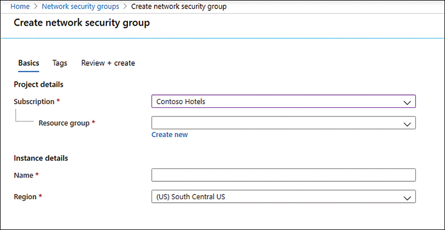
FIGURE 2-15 Initial parameters of the network security group
At this point, you have successfully created your NSG, and you can see that the default rules are already part of it. The next step is to create the custom rules, which can be inbound or outbound. (This example uses inbound rules.) The same operation could be done using the New-AzNetworkSecurityGroup PowerShell cmdlet, as shown in the following example:
New-AzNetworkSecurityGroup -Name "AZ500NSG" -ResourceGroupName "AZ500RG"  -Location
"westus"
Follow these steps to create an inbound rule that allows FTP traffic from any source to a specific server using Azure portal:
On the NSG page, under Settings in the left navigation pane, click Inbound Security Rules.
Click the Add button; the Add Inbound Security Rule blade appears, as shown in Figure 2-16.
On this blade, you start by specifying the source, which can be an IP address, a service tag, or an ASG. If you leave the default option (Any), you are allowing any source. For this example, leave this set to Any.
In the Source Port Ranges field, you can harden the source port. You can specify a single port or an interval. For example, you can allow traffic from ports 50 to 100. Also, you can use a comma to add another condition to the range, such as
50–100, 135, which specifies ports 50 through 100 and 135. Leave the default selection (*), which allows any source port.In the Destination field, the options are nearly the same as the Source field. The only difference is that you can select the VNet as the destination. For this example, change this option to IP Addresses and enter the internal IP address of the VM that you created at the beginning of this chapter.
In the Destination Port Ranges field, specify the destination port that will be allowed. The default port is 8080; for this example, change it to 21.

FIGURE 2-16 Creating an inbound security rule for your NSG
In the Protocol field, you can select which protocol you are going to allow; in this case, change it to TCP.
Leave the Action field set to Allow, which is the default selection.
You can also change the Priority of this rule. Remember that the lowest priority is evaluated first. For this example, change it to 101.
In the Name field, change it to AZ500NSGRule_FTP and click the Add button.
The NSG will be created, and a new rule will be added to the inbound rules. At this point, your inbound rules should look like the rules shown in Figure 2-17.

FIGURE 2-17 List of inbound rules
While these are the steps to create the inbound rule, this NSG has no use if it is not associated with a subnet or a virtual network interface. For this example, you will associate this NSG to a subnet. The intent is to block all traffic to this subnet and only allow FTP traffic to this specific server. Use the following steps to create this association:
At the left hand side of the NSG Inbound Security Rules page, in the navigation pane of the Network security group, under Settings, click Subnets.
Click the Associate button, and in the Virtual Network drop-down menu, select the VNet where the subnet resides.
After this selection, you will see that the Subnet drop-down menu appears; select the subnet and click the OK button.
You could also use PowerShell to create an NSG and then associate the NSG to a subnet. To create an NSG using PowerShell, use the New-AzNetworkSecurityRuleConfig cmdlet, as shown in the following example:
$MyRule1 = New-AzNetworkSecurityRuleConfig -Name ftp-rule -Description "Allow FTP"
-Access Allow -Protocol Tcp -Direction Inbound -Priority 100 -SourceAddressPrefix *
-SourcePortRange * -DestinationAddressPrefix * -DestinationPortRange 21
Application security group
If you need to define granular network security policies based on workloads that are centralized on application patterns instead of explicit IP addresses, you need to use the application security group (ASG). An ASG allows you to group VMs and secure applications by filtering traffic from trusted segments of your network, which adds an extra level of micro-segmentation.
You can deploy multiple applications within the same subnet and isolate traffic based on ASGs. Another advantage is that you can reduce the number of NSGs in your subscription. For example, in some scenarios, you can use a single NSG for multiple subnets of your virtual network and perform the micro-segmentation on the application level by using ASG. Figure 2-18 shows an example of how ASG can be used in conjunction with NSG.
In the example shown in Figure 2-18, two ASGs have been created to define the application pattern for a web application and another ASG to define the application pattern for a SQL database. Two VMs are part of each group, and the ASG is used in the routing table of the NSG located in subnet A. In the NSG routing table, you can specify one ASG as the source and destination, but you cannot specify multiple ASGs in the source or destination.

FIGURE 2-18 ASG used as the destination in the NSG routing table
When you deploy VMs, you can make them members of the appropriate ASGs. In case your VM has multiple workloads (Web App and SQL, for example), you can assign multiple ASGs to each application. This will allow you to have different types of access to the same VM according to the workload. This approach also helps to implement a zero-trust model by limiting access to the application flows that are explicitly permitted. Follow these steps to create an ASG:
Navigate to the Azure portal at https://portal.azure.com.
In the search bar, type application security, and under Services, click Application Security Groups.
In the Application Security Groups dashboard, click the Add button, which makes the Create An Application Security Group page appear, as shown in Figure 2-19.

FIGURE 2-19 Create An Application Security Group
In the Subscription drop-down menu, select the appropriate subscription for this ASG.
In the Resource Group drop-down menu, select the resource group in which this ASG will reside.
In the Name field, type a name for this ASG.
In the Region drop-down menu, select the appropriate region for this ASG and click the Review + Create button.
On the Review + Create button page, click the Create button.
Now that the ASG is created, you need to associate this ASG to the network interface of the VM that has the workload you want to control. Follow these steps to perform this association:
Navigate to the Azure portal at https://portal.azure.com.
In the search bar, type virtual, and under Services, click Virtual Machines.
Click in the VM that you want to perform this association.
On the VM’s page, in the Settings section, click the Networking option.
Click the Application Security Group tab, and the page shown in Figure 2-20 appears.
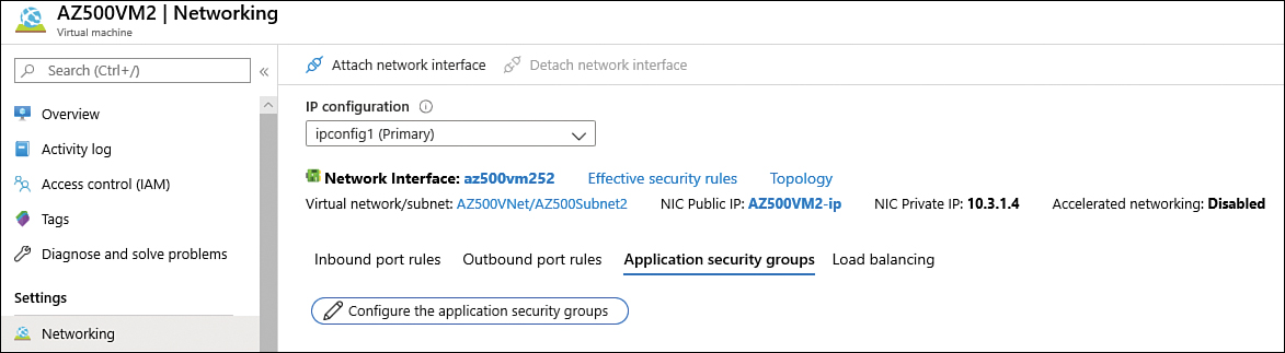
FIGURE 2-20 Associating the ASG to the virtual network interface card
Click the Configure The Application Security Groups button, and the Configure The Application Security Groups blade appears, as shown in Figure 2-21.

FIGURE 2-21 Selecting the ASG
Select the appropriate ASG and click the Save button.
You can also use the New-AzApplicationSecurityGroup cmdlet to create a new ASG, as shown in the following example:
New-AzApplicationSecurityGroup -ResourceGroupName "MyRG" -Name "MyASG" -Location
"West US"
Now when you create your new NSG rule for inbound or outbound traffic, you can select the ASG as source or destination.
Create and configure Azure Firewall
While NSG provides stateful package flow and custom security rules, you will need a more robust solution when you need to protect an entire virtual network. If your company needs a fully stateful, centralized network firewall as a service (FWaaS) that provides network and application-level protection across different subscriptions and virtual networks, you should choose Azure Firewall.
Also, Azure Firewall can be used in scenarios where you need to span multiple availability zones for increased availability. Although there’s no additional cost for an Azure Firewall deployed in an availability zone, there are additional costs for inbound and outbound data transfers associated with Availability Zones. Figure 2-22 shows an Azure Firewall in its own VNet and subnet, allowing some traffic and blocking other traffic based on a series of evaluations.

FIGURE 2-22 Azure Firewall topology
As shown in Figure 2-22, the Azure Firewall will perform a series of evaluations prior to allowing or blocking the traffic. Just as with an NSG, the rules in Azure Firewall are processed according to the rule type in priority order (lower numbers to higher numbers). A rule collection name may contain only letters, numbers, underscores, periods, or hyphens. You can configure NAT rules, network rules, and applications rules on Azure Firewall. Keep in mind that Azure Firewall uses a static public IP address for your virtual network resources, and you need that before deploying your firewall. Azure Firewall also supports learning routes via Border Gateway Protocol (BGP).
To evaluate outbound traffic, Azure Firewall will query the network and application rules. Just as with an NSG, no other rules are processed when a match is found in a network rule. Azure Firewall will use the infrastructure rule collection if there is no match. This collection is created automatically by Azure Firewall and includes platform-specific fully qualified domain names (FQDN). If there is still no match, Azure Firewall denies outgoing traffic.
Azure Firewall uses rules based on Destination Network Address Translation (DNAT) for incoming traffic evaluation. These rules are also evaluated in priority and before network rules. An implicit corresponding network rule to allow the translated traffic is added if a match is found. Although this is the default behavior, you can override this by explicitly adding a network rule collection with deny rules that match the translated traffic (if needed).
In Figure 2-22, you also saw that Azure Firewall leverages Microsoft Threat Intelligence during the traffic evaluation. The Microsoft Threat Intelligence is powered by Intelligent Security Graph and is used by many other services in Azure, including Microsoft Defender for Cloud.
Azure Firewall is available in two tiers, Premium and Standard. The Standard tier includes the following capabilities:
Built-in high availability
Availability Zones
Unrestricted cloud scalability
Application FQDN filtering rules
Network traffic filtering rules
FQDN tags
Service tags
Threat intelligence
Outbound SNAT support
Inbound DNAT support
Multiple public IP addresses
Azure Monitor logging
Forced tunneling
Web categories
Certifications
While these features are enough for many organizations, there will be scenarios where the environment is highly sensitive and regulated, which requires features only available in the next generation Firewall. These features are part of the Azure Firewall Premium tier, which includes:
TLS inspection With this capability it is possible to decrypt outbound traffic, analyze the data, and then encrypt the data again before sending it to the destination.
Intrusion detection and prevention system (IDPS) This is a network-based IDPS that enables you to monitor network traffic for malicious activity. In addition, IDPS enables you to log information about these activities, report it, and optionally create a mechanism to attempt to block it.
URL filtering This capability enhances the Azure Firewall’s FQDN filtering feature to consider an entire URL. For example, www.fabrikam.com/a/b instead of
www.fabrikam.com.Web categories This feature allows you to control user access to websites by categories such as gambling websites, social media websites, and others.
Now that you know the key components of the Azure Firewall, use the following steps to deploy and configure it:
Navigate to the Azure portal at https://portal.azure.com.
In the main dashboard, click Create A Resource.
Type firewall and click Firewall in the drop-down menu.
On the Firewall page, click the Create button, and the Create A Firewall blade appears, as shown in Figure 2-23.
If you have multiple subscriptions, make sure to click the Subscription drop-down menu and select the one that you want to use to deploy Azure Firewall.
In the Resource Group drop-down menu, select the resource group in which you want to deploy your Azure Firewall.
In the Instance Details section’s Name field, type the name for this Azure Firewall instance. There is a 50-character limit for the name.
In the Region drop-down menu, select the region where the Azure Firewall will reside.
In the Availability Zone drop-down menu, select the availability zone in which the firewall will reside.
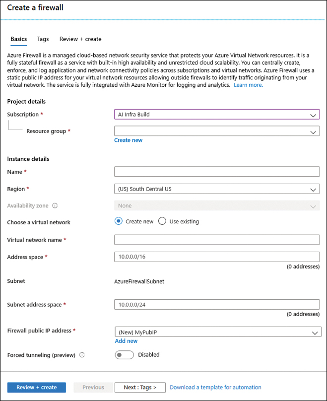
FIGURE 2-23 Creating a new Azure Firewall
In the Firewall Tier you can select the plan you can use.
In the Firewall Management section, you can select the use of Firewall policy or classic Firewall rules. Keep in mind that if you use a Firewall policy, you will need to select an existing policy or create a new one.
For the Choose Virtual Network option, select Use Existing and select an existing VNet.
In the Virtual Network drop-down menu, select the VNet to which you want to deploy Azure Firewall.
In the Firewall Public IP Address field, select an existing unused public IP address or click Add New to create a new one in case all your public IPs are already allocated.
You can either enable or disable Force Tunneling. The default option is Disabled. By enabling this option, you are instructing Azure Firewall to route all Internet-bound traffic to a designated next hop instead of going directly to the Internet. Keep in mind that if you configure Azure Firewall to support forced tunneling, you can’t undo this configuration. Leave the default selection and click the Review + Create button.
The creation of the Azure Firewall will take several minutes. After the deployment is complete, you can click the Go To Resource button.
You can also deploy a new Azure Firewall using the New-AzFirewall cmdlet, as shown in the following example:
New-AzFirewall -Name "azFw" -ResourceGroupName MyRG -Location centralus -VirtualNetwork
MyVNet -PublicIpAddress MyPubIP
Creating an application rule
Now that the Azure Firewall is created, you can start creating rules. To start, you are going to create an application rule to allow outbound access to www.bing.com. Follow these steps to create a rule:
On the page that you have open for the firewall you created, click Rules, as shown in Figure 2-24.

FIGURE 2-24 Firewall options
Click the Application Rule Collection tab and then click the + Add Application Rule Collection option. The Add Application Rule Collection page appears, as shown in Figure 2-25.
In the Name field, type a name for the rule; for this example, type Bing.
In the Priority field, type the priority for this rule; for this example, type 100.
In the Action drop-down menu, leave the default option (Allow).
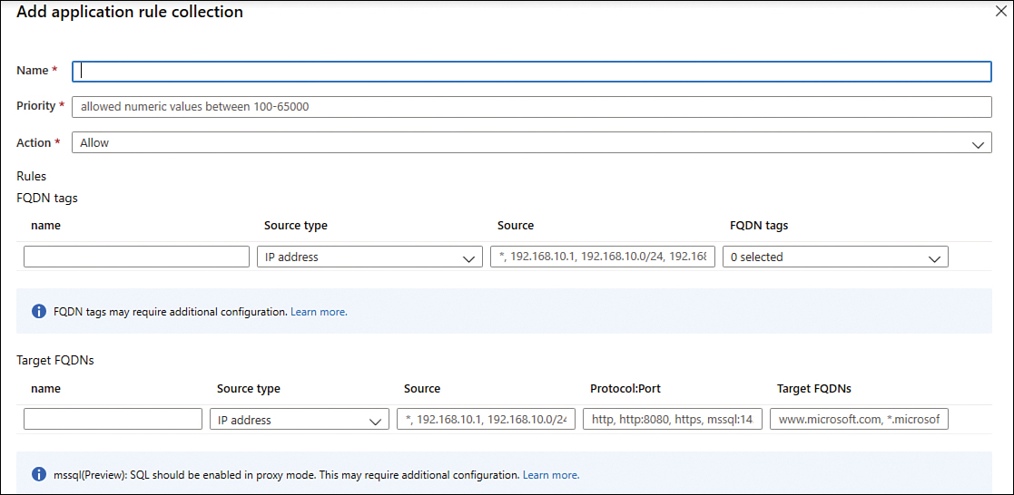
FIGURE 2-25 Creating a new application rule collection
No changes are necessary in the FQDN Tags field.
In the Target FQDNs field, type AllowBing and leave the Source Type set to IP Address.
Type * in the Source field.
In the Protocol:Port field, type http,https.
In the Target FQDNs field, type www.bing.com.
Click the Add button.
In case you want to perform the same configuration using PowerShell, you can use the New-AzFirewallApplicationRule cmdlet, as shown here:
$MyAppRule = New-AzFirewallApplicationRule -Name AllowBing -SourceAddress * '
  -Protocol http, https -TargetFqdn www.bing.com
$AppCollectionRule = New-AzFirewallApplicationRuleCollection -Name App-Coll01 '
  -Priority 100 -ActionType Allow -Rule $MyAppRule
$Azfw.ApplicationRuleCollections = $AppRuleCollection
Set-AzFirewall -AzureFirewall $Azfw
Creating a network rule
Creating a network rule is very similar to creating an application rule. For this example, you are going to create an outbound network rule that allows access to an external DNS Server. Follow these steps to create your network rule:
On the Firewalls rules page, click the Network Rule Collection tab.
Click the Add Network Rule Collection option; the Add Network Rule Collection blade appears, as shown in Figure 2-26.

FIGURE 2-26 Creating a new network rule collection
In the Name field, type DNS.
In the Priority field, type 200.
In the Action field, leave the default selection (Allow).
Under the IP Addresses section, type DNSOutbound in the Name field.
Select UDP in the Protocol field.
Leave IP Address selection in the Source Type field.
In the Source field, type the range of your subnet, such as 10.30.0.0/24.
Leave the IP Address selection in the Destination Type field.
In the Destination Address field, type the IP address of the external DNS.
In the Destination Port, type 53.
Click the Add button.
In case you want to perform the same configuration using PowerShell, you can use the New-AzFirewallNetworkRule cmdlet, as shown here:
New-AzFirewallNetworkRule -Name "DNSOutbound" -Protocol UDP -SourceAddress
"10.30.0.0/24" -DestinationAddress IP_of_the_DNSSErver -DestinationPort 53
Firewall logs
When system admins need to audit configuration changes in the Azure Firewall, they should use Azure Activity logs. For example, the creation of those two rules (application and network) will appear in the Activity Log, which will look similar to Figure 2-27.

FIGURE 2-27 Activity logs showing the changes in the Azure Firewall
While these actions are automatically logged in the Azure Activity Log, the diagnostic logging for application and network rules are not enabled by default. You can also enable Firewall metrics. These metrics are collected every minute and can be useful for alerting because they can be sampled frequently. When you enable metrics collection, the following metrics will be available for Azure Firewall:
Application rules hit count
Network rules hit count
Data processed
Firewall health state
SNAT port utilization
These metrics and the diagnostic logging for application and network rules can be enabled in the Azure Firewall dashboard. Use the following steps to enable these logs:
On the Firewalls page, in the left navigation pane, under the Monitoring section, click Diagnostic Settings. The Diagnostic Settings page appears, as shown in Figure 2-28.
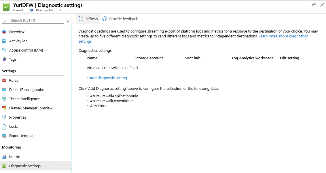
FIGURE 2-28 Diagnostic settings page
Click the Add Diagnostic Setting option, which makes the Diagnostic Settings blade appear, as shown in Figure 2-29.
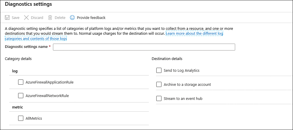
FIGURE 2-29 Diagnostic Settings page
In the Diagnostic Settings Name field, type a name for this setting.
In the Log section, enable AzureFirewallApplicationRule and AzureFirewallNetworkRule.
In the Metric section, enable AllMetrics.
In the Destination Details section, you can choose where you want to send the logs: Log Analytics, Storage Account, or Event Hub. If you need to retain logs for a longer duration for review as needed, choosing Storage Account is the best option. If you need to send the logs to a security information and event management (SIEM) tool, the Event Hub is the best option. If you need more real-time monitoring, Log Analytics is a better fit. Notice that you can select multiple options, which allows you to address multiple needs.
For this example, select Send To Log Analytics, and select the workspace in which the logs will reside.
Click Save and once it is saved, close the blade.
Notice that the name of your logging configuration now appears on the Diagnostic Settings page.
You can use the
Set-AzDiagnosticSettingcmdlet to enable diagnostic logging, as shown in the following example:Set-AzDiagnosticSetting -ResourceId /subscriptions/<subscriptionId>/ resourceGroups/<resource group name>/providers/Microsoft.Network/ azureFirewalls/<Firewall name> ' -StorageAccountId /subscriptions/<subscriptionId>/resourceGroups/<resource group name>/providers/Microsoft.Storage/storageAccounts/<storage account name> ' -Enabled $true
Now that the diagnostic logging is configured, click Logs in the left navigation pane in the Monitoring section. The Log Analytics workspace appears with the Azure Firewall schema, as shown in Figure 2-30.

FIGURE 2-30 Schema for the Azure Firewall in Log Analytics
To query on the Log Analytics workspace, you use Kusto Query Language (KQL). You can use the sample query to retrieve the logs that are related to the network rules:
AzureDiagnostics
| where Category == "AzureFirewallNetworkRule"
Create and configure Azure Firewall Manager
Azure Firewall Manager can be used when the organization needs a security management solution that enables centralized security policy and route management. Azure Firewall Manager can provide this type of benefit for two types of Azure network architecture:
Secured virtual hub: this type of network is utilized when the organization uses an Azure Virtual WAN Hub to create hub-and-spoke architectures. When security and routing policies are associated with such a hub, it is referred to as a secured virtual hub.
Hub virtual network: this type of network is utilized when the organization is using an Azure virtual network that they create and manage on their own. When security policies are associated with such a hub, it is referred to as a hub virtual network.
When designing the architecture of your Azure network, consider the technical requirements of the scenario. If these requirements include one or more of the items shown below, then you should use Azure Firewall Manager:
Centralized deployment and configuration of multiple Azure Firewall instances that span through different Azure regions and subscriptions
Centralized management of Azure Firewall policies across multiple secured virtual hubs
Ability to integrate with third-party Security-as-a-Service (SECaaS) providers to obtain additional network protection for VNet and branch Internet connections
Ability to route traffic to a secured hub for filtering and logging purposes without having to manually set up User Defined Routes (UDR) on spoke virtual networks
One of the main components of Azure Firewall Manager is the Firewall policy. This policy contains NAT, network and application rule collections, and Threat Intelligence settings. A Firewall policy is a global resource that can be used across multiple Azure Firewall instances and across regions and subscriptions. You can create a policy using Azure portal, REST API, templates, Azure PowerShell, and CLI. You can also migrate existing rules from Azure Firewall using the portal or Azure PowerShell to create policies.
You can create new policies, or you can create a policy inherited from other existing policies. Policies created with non-empty parent policies inherit all rule collections from the parent policy. It is important to mention that when you inherit a policy, any changes to the parent policy will be automatically applied down to associated firewall child policies.
When taking the AZ-500 exam, make sure to carefully read the scenario description and the organization’s requirements. Depending on the organization’s requirements, you will either create an Azure Firewall Manager to a virtual hub or a hub virtual network.
If you need to secure your cloud network traffic destined to private IP addresses, Azure PaaS, and the Internet, then you should deploy Azure Firewall Manager to a virtual hub. If you need to connect your on-premises network to an Azure virtual network to create a hybrid network, you can create a hub virtual network. By deploying Azure Firewall Manager to this hub virtual network, you are securing your hybrid network traffic destined to private IP addresses, Azure PaaS, and the Internet.
The main use case scenario for Azure Firewall Manager is the centralized management of policies across multiple secured virtual hubs. Azure Firewall Manager supports both classic rules and policies, though when designing your deployment, we recommend that you use policies. Azure Firewall Manager also supports Standard and Premium policies. If your deployment needs any of the components below, you should choose Standard policy:
NAT rules, Network rules, Application rules
Custom DNS, DNS proxy
IP Groups
Web Categories
Threat Intelligence
More advanced deployments may require capabilities that will only be available in the Premium policies, which are: TLS Inspection, Web Categories, URL Filtering, and IDPS.
Another scenario supported by Azure Firewall Manager is to leverage third-party security as a service (SECaaS) offerings to protect Internet access for your users. By using this integration, you can secure a hub with a supported security partner. Also, you can route and filter Internet traffic from your Virtual Networks (VNets) or branch locations within a region. The supported security partners are Zscaler, Check Point, and iboss.
The general deployment steps will also vary according to the deployment selection. If you decided to deploy Azure Firewall Manager for hub virtual networks, the overall steps are shown below:
Create a Firewall policy.
Create a hub-and-spoke architecture.
Select the supported provider, which in this case only Azure Firewall is supported.
Configure the appropriate routes.
Create and configure Azure Front Door
Consider an Azure deployment across different regions that needs to provide a high-performance experience for applications, and it is resilient to failures. For this type of scenario, Azure Front Door is the best solution.
Azure Front Door works at layer 7 (HTTP/HTTPS) and uses the anycast protocol with split TCP, plus Microsoft’s global network for improving global connectivity. By using split TCP-based anycast protocol, Front Door ensures that your users promptly connect to the nearest Front Door POP (point of presence).
You can configure Front Door to route your client requests to the fastest and most available application back end, which is any Internet-facing service hosted inside or outside of Azure. Some other capabilities included in Front Door are listed here:
Intelligent health probe Front Door monitors your back ends for availability and latency. According to its results, it will instant failover when a back end goes down.
URL-based routing Allows you to route traffic to the back end based on the URL’s path of the request. For example, traffic to
www.fabrikam.com/hr/*is routed to a specific pool, whereaswww.fabrikam.com/soc/*goes to another.Multiple-site hosting Enables you to configure a more efficient topology for your deployments by adding different websites to a single Front Door and redirecting to different pools.
Session affinity Uses cookie-based session affinity to keep the session in the same back end.
TLS termination Support for TLS termination at the edge.
Custom domain, SSL offloading, and certificate management You can let Front Door manage your certificate, or you can upload your own TLS/SSL certificate.
Application layer security Allows you to author your own custom web application firewall (WAF) rules for access control, and it comes with Azure DDoS Basic enabled. Front Door is also a layer 7 reverse proxy, which means it only allows web traffic to pass through to back ends and blocks other types of traffic by default.
URL redirection Allows you to configure different types of redirection, which includes HTTP to HTTPS redirection, redirection to different hostnames, redirection to different paths, or redirections to a new query string in the URL.
URL rewrite Allows you to configure a custom forwarding path to construct a request to forward traffic to the back end.
The diagram shown in Figure 2-31 reflects some of the features that were mentioned previously and gives you a better topology view of the main use case for Azure Front Door.
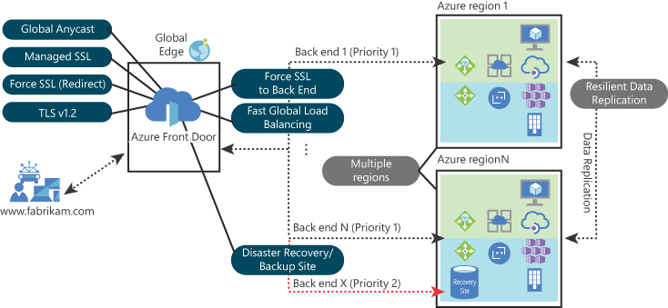
FIGURE 2-31 A sse case for Azure Front Door
Follow the steps below to configure your Azure Front Door:
Navigate to the Azure portal at https://portal.azure.com.
In the search bar, type front and under Services, click Front Doors.
On the Front Doors page, click the Add button; the Create A Front Door page appears, as shown in Figure 2-32.
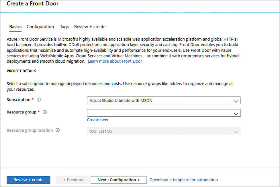
FIGURE 2-32 Azure Front Door creation page
In the Subscription drop-down menu, select the subscription that you want to use to create the Front Door.
In the Resource Group drop-down menu, select the resource group that you want for this Front Door.
Click the Next: Configuration button; the Configuration tab appears, as shown in Figure 2-33.
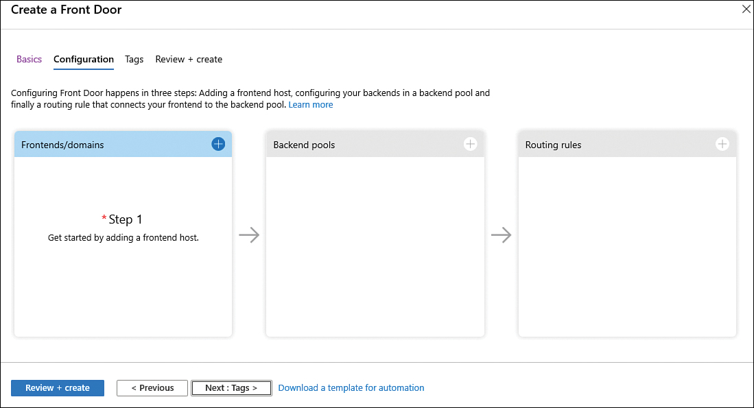
FIGURE 2-33 Initial Front Door configuration
Click the plus sign (+) in the first square, Frontends/Domains; the Add Front End Host blade appears, as shown in Figure 2-34.

FIGURE 2-34 Add A Frontend Host
In the Host Name field, type a unique name for this front end.
Front Door forwards requests originating from the same client to different back ends based on load-balancing configuration, which means that Front Door doesn’t use session affinity by default. However, some stateful applications usually prefer that subsequent requests from the same user land on the same back end that processed the initial request. In this case, you need to enable session affinity. For this example, leave the default selection in Session Affinity (Enabled).
If you want to use Web Application Firewall (WAF) to protect your web application, you can take advantage of the centralized management provided by Front Door. For this example, leave the default Disabled setting for Web Application Firewall and click the Add button.
Click the plus sign (+) in the second square, Back End Pools; the Add Back End Pool blade appears, as shown in Figure 2-35.
In the Name field, type a unique name for the back-end pool.
In the Back Ends section, click Add A Back End; the Add A Back End blade appears, as shown in Figure 2-36.
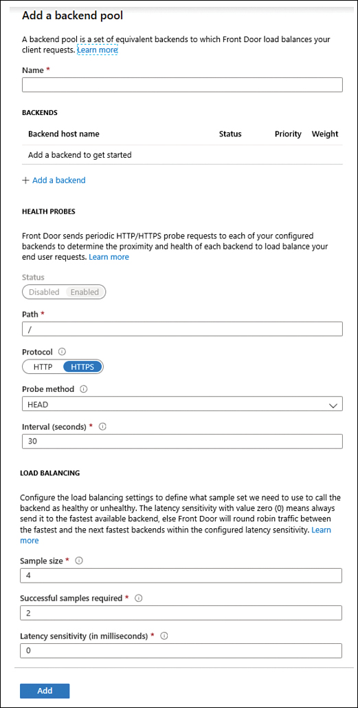
FIGURE 2-35 Add A Back End Pool
In the Back End Host Type drop-down menu, you can choose the type of resource you want to add. Select App Service in the drop-down menu.
Once you make this selection, the remaining parameters should be automatically filled with the default options. Review the values and click the Add button.
Now that you are back to the Add Back End Pool blade, review the options under the Health Probes section and notice that the default setting for Probe Method is
HEAD. TheHEADmethod is identical toGET; the difference is that the server must not return a message-body in the response. This is also the recommended setting to lower the load on your back ends (as well as the cost).
FIGURE 2-36 Configuring a new backend
The Load Balancing settings for the back-end pool define how health probes are evaluated. These settings are used to determine whether the back end is healthy or unhealthy. The Sample Size is used to determine how many sample health probes are necessary to consider the state of the back end (health evaluation). The Successful Samples Required is the threshold for how many samples must succeed to be considered successful. The Latency Sensitivity (in milliseconds) option is used when you want to send requests to back ends within the established latency measurement sensitivity range.
Leave the default selections and click the Add button.
Click the plus sign (+) in the third square; Routing Rules; the Add Rule blade appears, as shown in Figure 2-37.

FIGURE 2-37 Adding a new rule
In the Name field, type a unique name for this routing rule.
Under the Patterns To Match section, you can add a specific pattern that you want to use. When Front Door is evaluating the request, it looks for any routing with an exact match on the host. If no exact front-end hosts match, it rejects the request and sends a 400 Bad Request error. After determining the specific front-end host, Front Door will filter the routing rules based on the requested path. For this example, leave the default selections.
Under the Route Details section, you can configure the behavior of the route. In the Route Type option, you can select whether you want to forward to the back-end pool or redirect to another place. For this example, leave this set to Forward, which is the default. Enable the URL Rewrite option if you want to create a custom forwarding path. The Caching option is disabled by default, which means that requests that match to this routing rule will not attempt to use cached content. In order words, requests will always fetch from the back end. Leave all the default selections in this section and click the Add button.
Click the Review + Create button, review the summary of your configuration, and click the Create button to finish.
Wait until the deployment is finished. Once it is finished, click the Go To Resource button to see the Front Door dashboard.
It will take a few minutes for the configuration to be deployed globally everywhere after you finish creating your Front Door.
Web application firewall
Web Application Firewall (WAF) can be used on Front Door. Azure also allows you to deploy WAF in other ways, so it is important to understand the design requirements before deciding which WAF deployment you should use.
Review the flowchart available at http://aka.ms/wafdecisionflow to better understand WAF’s features, which include Azure Load Balancer, Application Gateway, and Azure Front Door. If your scenario has the following characteristic, WAF with Front Door is a good choice:
Your app uses HTTP/HTTPS.
Your app is Internet-facing.
Your app is globally distributed across different regions.
Your app is hosted in PaaS (such as an Azure App Service).
Consider deploying WAF on Front Door when you need a global and centralized solution. When using WAF with Front Door, the web applications will be inspected for every incoming request delivered by Front Door at the network edge.
Create and configure Web Application Firewall (WAF)
In a scenario where you need to protect your web applications from common threats, such as SQL injection, cross-site scripting, and other web-based exploits, using Azure Web Application Firewall (WAF) on Azure Application Gateway is the most appropriate way to address these needs. WAF on Application Gateway is based on Open Web Application Security Project (OWASP) core rule set 3.1, 3.0, or 2.2.9. These rules will be used to protect your web apps against the top 10 OWASP vulnerabilities, which you can find at https://owasp.org/www-project-top-ten.
You can use WAF on Application Gateway to protect multiple web applications. A single instance of Application Gateway can host up to 40 websites, and those websites will be protected by a WAF. Even though you have multiple websites behind the WAF, you can still create custom policies to address the needs of those sites. The diagram shown in Figure 2-38 has more details about the different components of this solution.
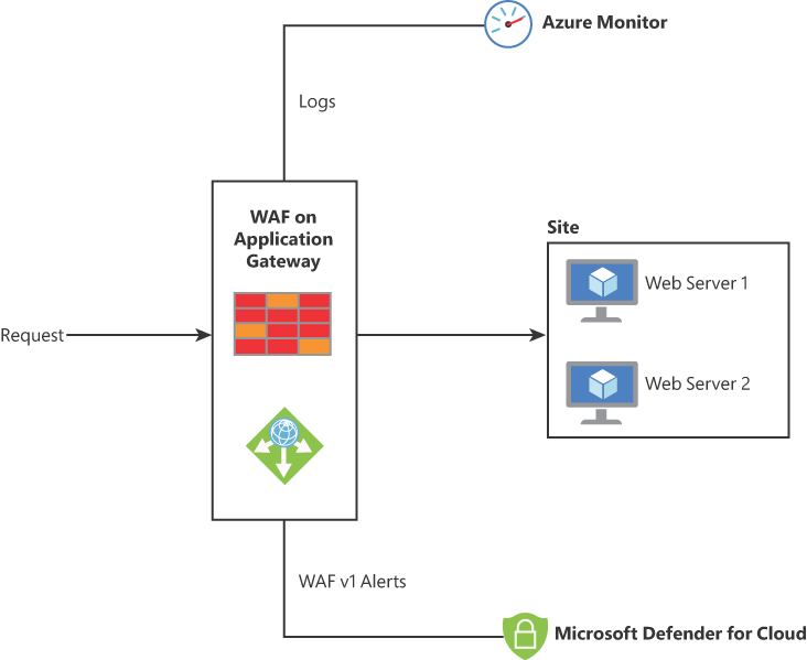
FIGURE 2-38 Different integration components for WAF on Application Gateway
In the example shown in Figure 2-38, a WAF Policy has been configured for the back-end site. This policy is where you define all rules, custom rules, exclusions, and other customizations, such as a file upload limit.
WAF on Application Gateway supports Transport Layer Security (TLS) termination, cookie-based session affinity, round-robin load distribution, and content-based routing. The diagram shown in Figure 2-38 also highlights the integration with Azure Monitor, which will receive all logs related to potential attacks against your web applications. WAV v1 alerts will also be streamed to Microsoft Defender for Cloud, and they will appear in the Security Alert dashboard.
Depending on the scenario requirement, you can configure WAF on the Application Gateway to operate in two different modes:
Detection mode This mode will not interfere with traffic when suspicious activity occurs. Rather than blocking suspicious activity, this mode only detects and logs all threat alerts. For this mode to work properly, diagnostic logging and the WAF log must be enabled.
Prevention mode As the name implies, this mode blocks traffic that matches the rules. Blocked requested generate a 403 Unauthorized Access message. At that point, the connection is closed, and a record is created in the WAF logs.
When reviewing the WAF log for a request that was blocked, you will see a message that contains some fields that are similar to this example:
Mandatory rule. Cannot be disabled. Inbound Anomaly Score Exceeded (Total Inbound Score:
5 - SQLI=0,XSS=0,RFI=0,LFI=0,RCE=0,PHPI=0,HTTP=0,SESS=0): Missing User Agent Header;
individual paranoia level scores: 3, 2, 0, 0
The anomaly score comes from the OWASP 3.x rules, which have a specific severity: Critical, Error, Warning, or Notice. The previous message indicates that the total inbound score is 5, which translates to a severity equal to Critical. It is important to emphasize that the traffic will not be blocked until it reaches the threshold, which is 5. This means that if traffic matches the block rule but has an anomaly score of 3, it will not be blocked, though the message that you will see in the WAF log says that it is blocked. The severity levels are 5 (Critical), 4 (Error), 3 (Warning), and 2 (Notice).
Configure resource firewall
In addition to Azure Firewall, you can also leverage the native firewall-related capabilities for different services. Azure Storage and SQL Database are examples of Azure services that have this functionality.
When you leverage this built-in functionality to harden your resources, you are adding an extra layer of security to your workload and following the defense in depth strategy, as shown in Figure 2-39.
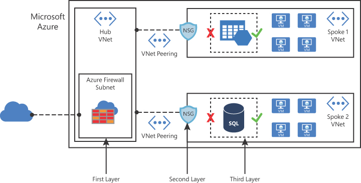
FIGURE 2-39 Multiple layers of protection to access the resource
Azure storage firewall
When you enable this feature in Azure Storage, you can better control the level of access to your storage accounts based on the type and subset of networks used. When network rules are configured, only applications requesting data over the specified set of networks can access a storage account.
You can create granular controls to limit access to your storage account to requests coming from specific IP addresses, IP ranges, or from a list of subnets in an Azure VNet. The firewall rules created on your Azure Storage are enforced on all network protocols that can be used to access your storage account, including REST and SMB.
Because the default storage accounts configuration allows connections from clients on any other network (including the Internet), it is recommended that you configure this feature to limit access to selected networks. Follow these steps to configure Azure Storage firewall:
Navigate to the Azure portal at https://portal.azure.com.
In the search bar, type storage, and under Services, click Storage Accounts.
Click the storage account for which you want to modify the firewall settings.
On the storage account page, under the Settings section in the left navigation pane, click the Firewalls And Virtual Networks option; the page shown in Figure 2-40 appears.

FIGURE 2-40 Azure storage firewall and virtual network settings
Under Allow Access From, click Selected Networks; the options shown in Figure 2-41 will become available.
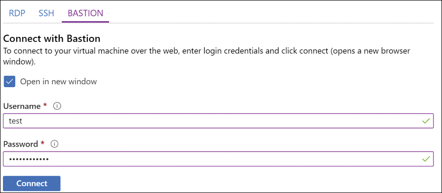
FIGURE 2-41 Azure storage firewall settings
Under the Virtual networks section, you could either add a new VNet or assign this storage account to a specific VNet.
Under the Firewall section, you can harden the address range that can have access to this storage account. For that, you need to type the IP addresses or the range using CIDR format. Keep in mind that services deployed in the same region as the storage account use private Azure IP addresses for communication. Therefore, you cannot restrict access to specific Azure services based on their public outbound IP address range.
Under the Exceptions section, you can enable or disable the following options:
Allow Trusted Microsoft Services To Access This Storage Account Enabling this option will grant access to your storage account from Azure Backup, Azure Event Grid, Azure Site Recovery, Azure DevTest Labs, Azure Event Hubs, Azure Networking, Azure Monitor, and Azure SQL Data Warehouse.
Allow Read Access To Storage Logging From Any Network Enable this point if you want to allow this level of access.
Allow Read Access To Storage Metrics From Any Network Enable this option if you need the storage metrics to be accessible from all networks.
Once you finish configuring, click the Save button.
If you want to quickly deny network access to the storage account, you can use the Update-AzStorageAccountNetworkRuleSet cmdlet, as shown here:
Update-AzStorageAccountNetworkRuleSet -ResourceGroupName "MyRG" -Name "mystorage"
-DefaultAction Deny
Azure SQL database firewall
When configuring your Azure SQL database, you can restrict access to a specific network by using the server-level firewall rules or database-level firewall rules. These rules can enable or disable access from clients to all the databases within the same SQL Database server. These rules are stored in the master database.
If your database is accessible from the Internet and a computer tries to connect to it, the firewall first checks the originating IP address of the request against the database-level IP firewall rules for the database that the connection requests. If the address isn’t within a range in the database-level IP firewall rules, the firewall checks the server-level IP firewall rules.
The server-level firewall rules can be configured via the Azure portal, whereas the database-level firewall needs to be configured on the database itself by using the sp_set_database_firewall_rule SQL command. To configure the server-level firewall, follow these steps:
Navigate to the Azure portal at https://portal.azure.com.
In the search bar, type database, and under Services, click SQL Databases.
Click the database for which you want to modify the server-level firewall settings.
In the Overview page, click the Set Server Rule button, as shown in Figure 2-42.

FIGURE 2-42 Selecting the option to configure the server-level firewall
The Firewall settings page appears, as shown in Figure 2-43.

FIGURE 2-43 Server-level Firewall Settings options
Under Deny Public Network Access option, select Yes if you want to prohibit access from the Internet or No if you want to allow Internet access to this database.
The Connection Policy option allows you to configure how clients can connect to Azure SQL. The available options are
Default The default policy is basically a redirect for all client connections originating inside of Azure and proxy for all client connections originating outside.
Policy By selecting this option, all connections are proxied via the Azure SQL Database gateways (which varies according to the Azure region). This setting will increase latency and reduce throughput.
Redirect By selecting this option, all clients will establish connections directly to the node hosting the database, which reduces latency and improves throughput.
Under Allow Azure Services And Resources To Access This Server, you have the option to Enable or Disable this type of access.
Next are three fields, Rule Name, Start IP, and End IP, which allow you to create filters for client connections.
The last option that you can configure is the Virtual Networks setting, which allows you to either create or add an existing VNet.
Once you finish configuring, click the Save button.
Azure Key Vault Firewall
Just like the previous resources, Azure Key Vault also allows you to create network access restrictions by using Key Vault firewall, which applies to Key Vault’s data plane. This means that operations such as creating a new vault or deleting or modifying the settings won’t be affected by the firewall rules. Below are two use-case scenarios for Azure Key Vault Firewall:
Contoso needs to implement Azure Key Vault to store encryption keys for its applications. Contoso wants to block access to its keys for requests coming from the Internet.
Fabrikam implemented Azure Key Vault, and now it needs to lock down access to its keys and enable access only to Fabrikam’s applications and a shortlist of specific hosts.
To configure Azure Key Vault Firewall, you should first enable the Key Vault Logging using the following sequence of PowerShell commands:
$storagea = New-AzStorageAccount -ResourceGroupName ContosoResourceGroup -Name
fabrikamkeyvaultlogs -Type Standard_LRS -Location 'East US'
$kvault = Get-AzKeyVault -VaultName 'ContosoKeyVault'
Set-AzDiagnosticSetting -ResourceId $kvault.ResourceId -StorageAccountId $storagea.Id
-Enabled $true -Category AuditEvent
In this sequence, you will create a new storage account to store the logs, obtain the Key Vault information, and finally, configure the diagnostic setting for your Key Vault.
After finishing this part, you can go to the Azure portal, open your Key Vault, and in the left navigation pane under the Settings section, click Networking > Private Endpoint And Selected Networks, as shown in Figure 2-44.
On this page, you can click the Add Existing Virtual Networks or Add New Virtual Networks options to start building your list of allowed virtual networks to access your Key Vault. Keep in mind that once you configure those rules, users can only perform Key Vault data plane operations when their requests originate from this list of allowed virtual networks. The same applies when users are trying to perform data plane operations from the portal, such as listing the keys.

FIGURE 2-44 Azure Key Vault Firewall configuration
In Figure 2-44, notice the Allow Trusted Microsoft Services To Bypass This Firewall option, which is set to Yes by default. This will allow the following services to have access to your Key Vault regardless of the firewall configuration: Azure Virtual Machines deployment service, Azure Resource Manager template deployment service, Azure Application Gateway v2 SKU, Azure Disk Encryption volume encryption service, Azure Backup, Exchange Online, SharePoint Online, Azure Information Protection, Azure App Service, Azure SQL Database, Azure Storage Service, Azure Data Lake Store, Azure Databricks, Azure API Management, Azure Data Factory, Azure Event Hubs, Azure Service Bus, Azure Import/Export, and Azure Container Registry.
Azure App Service Firewall
You might also want to harden the network access for your apps that are deployed via Azure App Service. Although the terminology used in this section refers to “Azure App Service Firewall,” what you are really implementing is a network-level access-control list. The access restrictions capability in Azure App Service is implemented in the App Service front-end roles. These front-end roles are upstream of the worker hosts where your code runs.
A common exam scenario for the implementation of this capability is when you need to restrict access to your app from certain VNets or the Internet. On the AZ-500 exam, make sure to carefully read the scenario because, in this case, you are adding restrictions to access the app itself, not the host.
To configure access restrictions on your Azure App Services, open the Azure portal, open the App Services dashboard, click your app service or Azure function, and in the Settings section, click Networking. The Access Restrictions option is shown at the right (see Figure 2-45).
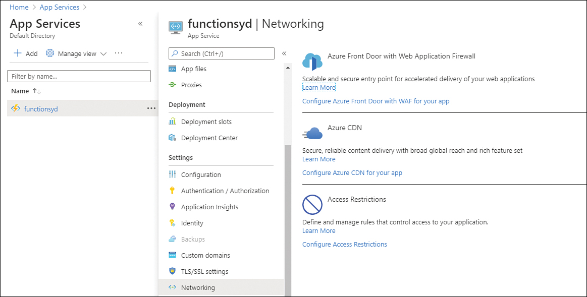
FIGURE 2-45 Azure App Services access restriction
To start the configuration, click Configure Access Restrictions in the Access Restriction section. You will see the Access Restriction page, as shown in Figure 2-46. The initial table is blank (no rules), and you can click Add Rule to start configuring your restrictions.
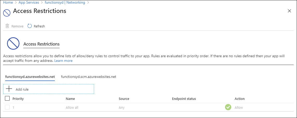
FIGURE 2-46 Adding Access Restrictions
It is recommended that you schedule a maintenance window to configure these restrictions because any operation (add, edit, or remove) in those rules will restart your app for changes to take effect.
Implement Azure service endpoints
You can also have a VNet that has only PaaS services and allow these services to be accessible outside of the VNet in which they reside. For example, the database admin needs to access the Azure SQL Database from the Internet. In this scenario, the database admin needs to create a service endpoint to allow secure access to the database.
At the time this chapter was written, the following Azure services supported service endpoint configuration:
Azure Storage
Azure SQL Database
Azure SQL Data Warehouse
Azure Database for PostgreSQL server
Azure Database for MySQL server
Azure Database for MariaDB
Azure Cosmos DB
Azure Key Vault
Azure Service Bus
Azure Event Hubs
Azure Data Lake Store Gen 1
Azure App Service
Azure Container Registry
From a security perspective, service endpoints provide the ability to secure Azure service resources to your VNet by extending the VNet identity to the service. After enabling service endpoints in your VNet, you can add a VNet rule to secure the Azure service resources to your VNet. By adding this rule, you are enhancing the security by fully removing public Internet access to resources and allowing traffic only from your virtual network.
Another advantage of using a service endpoint is traffic optimization. Service endpoint always takes service traffic directly from your VNet to the service on the Microsoft Azure backbone network, which means that the traffic is kept within the Azure backbone network. By having this control, you can continue auditing and monitoring outbound Internet traffic from your VNet without affecting service traffic.
The VNet service endpoint allows you to harden the Azure service access to only allowed VNet and subnet access. This adds an additional level of security to the network and isolates the Azure service traffic. All traffic using VNet service endpoints flows over the Microsoft backbone, thus providing another layer of isolation from the public Internet. You can also fully remove public Internet access to the Azure service resources and allow traffic only from their virtual networks through a combination of IP firewall and access control list on the VNet, which protects the Azure service resources from unauthorized access.
To configure a virtual network service endpoint, you will need to perform these two main actions:
Enable service endpoint in the subnet
Add a service endpoint to your VNet
If you are configuring Azure Storage, you also need to configure a service endpoint policy.
Enabling a service endpoint on the subnet can be done during the creation of the subnet or after the subnet is created. In the proprieties of the subnet, you can select the service endpoint in the Services drop-down menu, as shown in Figure 2-47.
FIGURE 2-47 Service Endpoints configuration on the subnet
To configure virtual network service endpoints on your virtual network, use the following steps:
Navigate to the Azure portal at https://portal.azure.com.
In the search bar, type virtual networks; under Services, click Virtual Networks.
Click the virtual network for which you want to configure the service endpoint.
In the left pane, click Service Endpoint, as shown in Figure 2-48.
Click the Add button.
In the Add Service Endpoints page, click the drop-down menu and select the Azure Service that you want to add.

FIGURE 2-48 Configuring a VNet service endpoint
Azure private endpoints and Private Links
When referring to a private endpoint in Azure, you are basically referring to a network interface that has a private IP address obtained from a virtual network. This network interface is then connected privately and securely to an Azure service via a Private Link. In this case, the Azure service can be an Azure Storage, Azure SQL, an Azure Cosmos DB, or your own service using Private Link service.
When you use private endpoints, the traffic is secured to a Private Link resource. An access control validation is done by the platform to check the network connections are reaching only the specified Private Link resource. If you need to access more resources within the same Azure service, you will need extra private endpoints.
It is very important to mention that a private endpoint enables connectivity between the consumers from the same virtual network, regionally peered virtual networks, globally peered virtual networks, on-premises using VPN or ExpressRoute, and services powered by Private Link. Another important consideration is that network connections will only be allowed to be initiated by clients that are connecting to the private endpoint. Service providers don’t have a routing configuration to create connections into service consumers.
An Azure Private Link service is the reference to your service that is powered by Azure Private Link. After you create a Private Link service, Azure will generate a globally unique, named moniker called “alias” based on the name you provide for your service.
Implement Azure DDoS protection
By default, Azure Distributed denial of service (DDoS) basic protection is already enabled on your subscription. This means that traffic monitoring and real-time mitigation of common network-level attacks are fully covered and provide the same level of defense as the ones utilized by Microsoft’s online services.
While the basic protection provides automatic attack mitigations against DDoS, there are some capabilities that are only provided by the DDoS Standard tier. The organization’s requirements will lead you to determine which tier you will utilize. If Contoso needs to implement DDoS protection on the application level, it needs to have real-time attack metrics and resource logs available to its team. Contoso also needs to create post-attack mitigation reports to present to upper management. These requirements can only be fulfilled by the DDoS Standard tier. Table 2-2 provides a summary of the capabilities available for each tier:
TABLE 2-2 Azure DDoS Basic versus Standard
Capability | DDoS Basic | DDoS Standard |
Active traffic monitoring and always-on detection | X | X |
Automatic attack mitigation | X | X |
Availability guarantee | Per Azure region. | Per application. |
Mitigation policies | Tuned per Azure region volume. | Tuned for application traffic volume. |
Metrics and alerts | Not available. | X |
Mitigation flow logs | Not available. | X |
Mitigation policy customization | Not available. | X |
Support | Yes, but it is a best-effort approach. In other words, there is no guarantee support will address the issue. | Yes, and it provides access to DDoS experts during an active attack. |
SLA | Azure region. | Application guarantee and cost protection. |
Pricing | Free. | Monthly usage. |
To configure Azure DDoS, your account must be a member of the Network Contributor role, or you can create a custom role that has read, write, and delete privileges under Microsoft.Network/ddosProtectionPlans and action privilege under Microsoft.Network/ ddosProtectionPlans/join. Your custom role also needs to have read, write, and delete privileges under Microsoft.Network/virtualNetworks. After you grant access to the user, use the following steps to create a DDoS Protection plan:
Navigate to the Azure portal at https://portal.azure.com.
In the search bar, type DDoS, and under Services, click DDoS Protection Plans.
On the DDoS Protection Plans page, click the Add button; the Create A DDoS Protection Plan page appears, as shown in Figure 2-49.
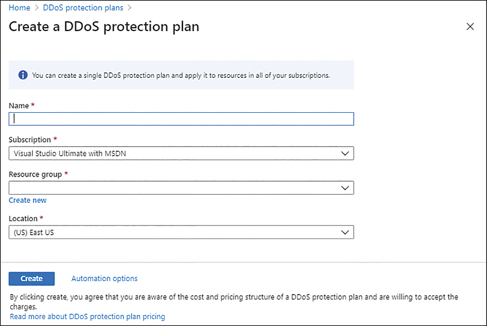
FIGURE 2-49 Create A DDoS Protection Plan
In the Name field, type the name for this DDoS protection.
In the Subscription field, select the appropriate subscription.
In the Resource group field, click the drop-down menu and select the resource group that you want.
In the Location field, select the region for the DDoS.
Before you click the Create button, read the note that is located under this button. This note emphasizes that by clicking Create, you are aware of the pricing for DDoS protection. Because there is no trial period for this feature, you will be charged during the first month of utilizing this feature.
After clicking Create, go to the search bar, type network, and click Virtual Networks.
Click the virtual network for which you want to enable the DDoS Standard.
In the left navigation pane, click the DDoS Protection option.
Click the Standard option, as shown in Figure 2-50.

FIGURE 2-50 Enabling DDoS Standard on the VNet
Click the DDoS Protection Plan drop-down menu and select the DDoS protection plan that you created in step 9.
Click the Save button.
At this point, you can configure Azure Monitor to send alerts by leveraging DDoS protection metrics. To do that, open Azure Monitor, click Metrics, select the scope of the public IP address located in the VNet where DDoS Standard is enabled, click the Metric drop-down menu, and select Under DDoS Attack Or Not, as shown in Figure 2-51.
To access a DoS attack mitigation report, you need to first configure diagnostic settings. This report uses the Netflow protocol data to provide detailed information about the DDoS attack on your resource. To configure this option, click Diagnostic Settings in the Settings section in the Azure Monitor blade, as shown in Figure 2-52.

FIGURE 2-51 Monitoring DDoS activity
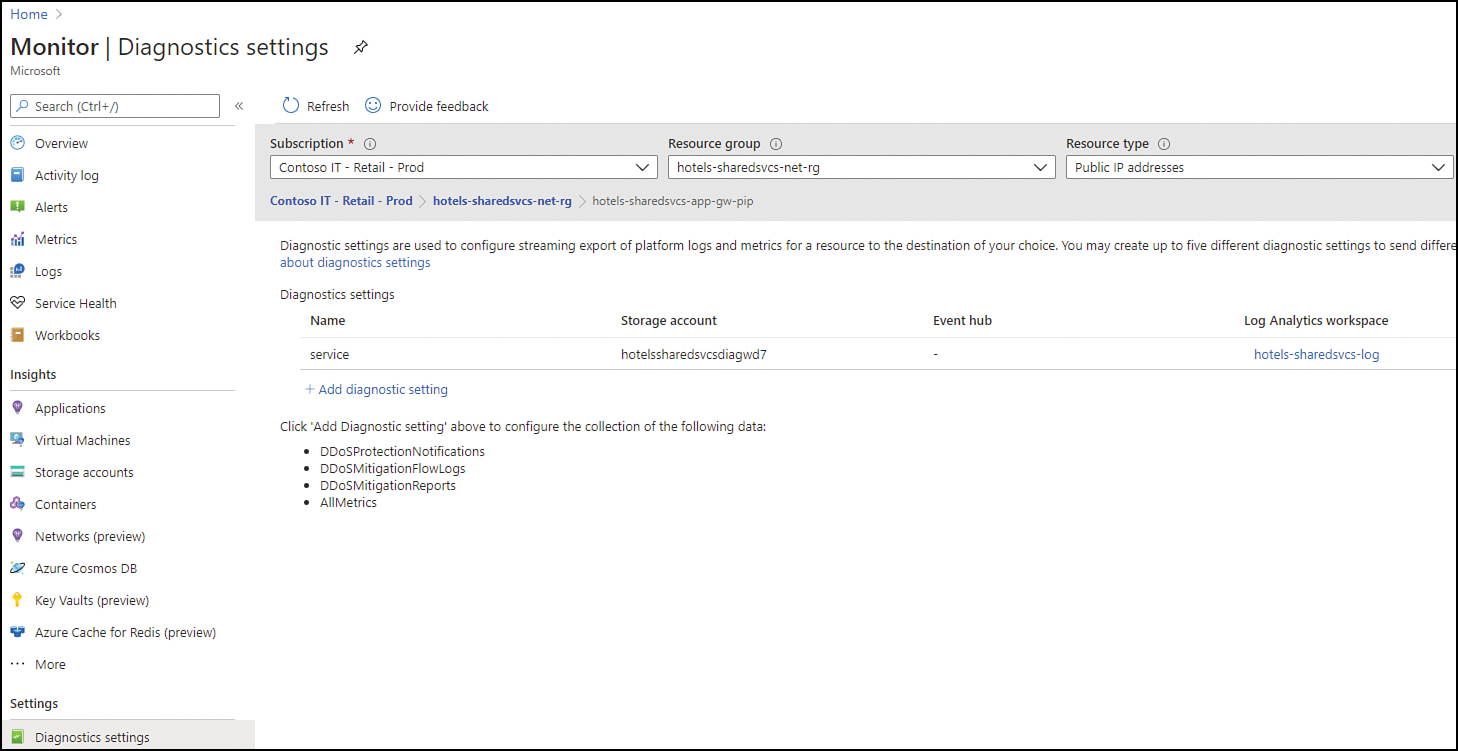
FIGURE 2-52 Configuring diagnostic logging
As you can see in the bottom part of the right blade, this page allows you to configure diagnostic logging for DDoSProtectionNotifications, DDoSMitigationFlowLogs, and DDoSMitigationReports. Just like any other diagnostic setting, you can store this data in a storage account, Event Hub, or a Log Analytics workspace.
Besides these options, is important to mention that Microsoft Defender for Cloud will also surface security alerts generated by DDoS Protection. There are two main alerts that could be triggered by this service and surfaced in Defender for Cloud:
DDoS Attack detected for Public IP
DDoS Attack mitigated for Public IP
Skill 2.2: Configure advanced security for compute
This section of the chapter covers the skills necessary to configure advanced security for compute, according to the Exam AZ-500 outline.
Configure Azure endpoint protection for virtual machines (VMs)
Endpoint protection is an imperative part of your security strategy, and these days, you can’t have endpoint protection without an antimalware solution installed on your computer.
Consider a scenario in which you provision a new VM that doesn’t have an endpoint protection configured. Wouldn’t it be ideal to have a solution that alerts you to the fact that an endpoint protection is missing in that VM? This is exactly what happens when you have Microsoft Defender for Cloud enabled in your subscription.
Follow these steps to access Defender for Cloud and review the endpoint protection recommendations:
Navigate to the Azure portal at https://portal.azure.com.
In the search bar, type security, and under Services, click Microsoft Defender for Cloud.
In Defender for Cloud main dashboard, under the Resource Security Hygiene section, click Compute & Apps.
In the resulting list, click the Install Endpoint Protection Solution On Virtual Machines option; the Endpoint Protection Not Installed On Azure VMs page appears, as shown in Figure 2-53.
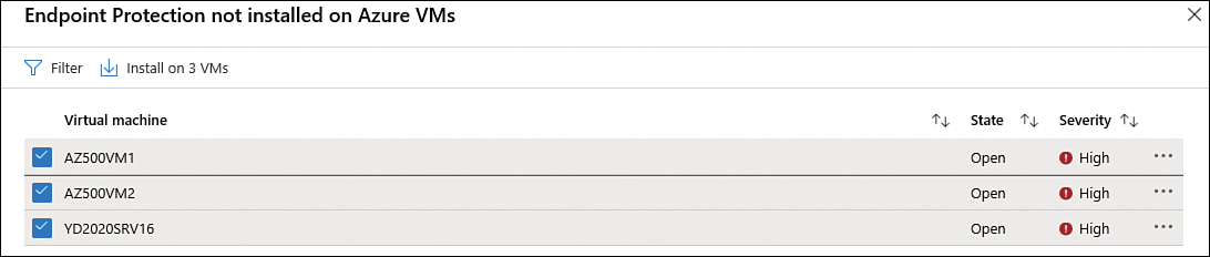
FIGURE 2-53 List of VMs that don’t have an endpoint protection solution installed
Select the VM on which you want to install the endpoint protection and click the Install On 1 VM button. The Select Endpoint Protection page appears, as shown in Figure 2-54.
FIGURE 2-54 Selecting the available endpoint protection solution to install
Defender for Cloud automatically suggests that you install the Microsoft Antimalware for Azure, which is a free real-time protection that helps identify and remove viruses, spyware, and other malicious software. Click the Microsoft Antimalware option; the Microsoft Antimalware page appears, as shown in Figure 2-55.

FIGURE 2-55 Microsoft Antimalware installation
Click the Create button; the Install Microsoft Antimalware blade appears, as shown in Figure 2-56.

FIGURE 2-56 Installation options
If you need to create an endpoint protection exclusion list, this is where you would do that. For example, let’s say you are aware that you want to avoid issues caused by antimalware scans of the files used by your app. You can add the paths used by this application in the exclusion list. This blade contains the following options:
Excluded Files And Locations Here, you can specify any paths or locations to exclude from the scan. To add multiple paths or locations, separate them with semicolons. This is an optional setting.
Excluded Files And Extensions This box lets you specify filenames or extensions to exclude from the scan. Again, to add multiple names or extensions, you separate them with a semicolon. Note that you should avoid using wildcard characters.
Excluded Processes Use this box to specify any processes that should be excluded from the scan. Again, use semicolons to separate multiple processes.
Real-Time Protection By default, this check box is enabled. Unless you have a good business reason to do otherwise, you should leave it that way.
Run a Scheduled Scan Selecting this check box enables you to run a scheduled scan.
Scan Type If you selected the Run A Scheduled Scan check box, you can use this drop-down menu to specify the type of scan. (A quick scan is run by default.)
Scan Day If you selected the Run A Scheduled Scan check box, you can use this drop-down menu to specify the day that the scan will run.
Scan Time If you selected the Run A Scheduled Scan check box, you can use this drop-down menu to specify what time the scan will run. The time is indicated in increments of 60 minutes (60 = 1 AM, 120 = 2 AM, and so on).
After you customize the options according to your needs, click the OK button.
After this step, the installation process will start. You can close the Defender for Cloud dashboard at this point.
Often, you will want to see an immediate reflection of the changes you made in the dashboard. However, be aware that the Defender for Cloud dashboard has different refresh times, which vary according to the objects. For example, operating system security configurations data are updated within 48 hours, and Endpoint Protection data is updated within 8 hours. This means that even if the installation of the endpoint succeeds in the next five minutes after you started, the dashboard will only reflect that installation in the next refresh cycle.
Having said that, it is important to mention that if the antimalware that was installed on the machine identifies a malicious code running, it will immediately trigger an alert. This alert will appear in the Security Alerts dashboard, as shown in Figure 2-57.

FIGURE 2-57 The Alert that appears in the Security Alert dashboard when Microsoft Antimalware takes an action
When you open this alert, you will see more details about the operation, which include the attacked resource, subscription, threat status, and file path, as shown in Figure 2-58.
Having an endpoint protection installed is only the first step to enhance the overall protection of your VM. There are many other aspects of VM security that need to be taken into consideration, and hardening is one of those. (See the next section.) Beyond hardening, what else can be implemented to secure a VM? Let’s start with access control. In a scenario in which an organization has multiple subscriptions, you might need a way to manage access efficiently. Establishing a good access control policy is one way to do just that.
In Azure, you can use Azure policies to create conventions for resources and create customized policies to control access. You can apply these policies to resource groups and the VMs that belong to those resource groups will inherit those policies. You can implement those policies at the management group level if you have multiple subscriptions that should receive the same policy.

FIGURE 2-58 Details about an alert are triggered in Microsoft Defender for Cloud when malware is detected.
When configuring access control, always make sure to use the least-privilege approach. You can leverage built-in Azure roles to allow users to access and set up VMs. Instead of giving a higher level of access, you can assign a user to the Virtual Machine Contributor role, and that user will inherit the rights to manage VMs, though the user won’t be able to manage the virtual network or storage account to which he or she is connected. The same applies for users who need access to Microsoft Defender for Cloud to visualize the recommendations for their VMs; they should have the Security Reader role, which will enable them to see recommendations but will not allow them make changes to the configuration.
While the Defender for Cloud provides good insights regarding the current security posture of your workloads, you should also consider the threat detection for VMs that comes with Defender for Servers. Defender for Servers has Virtual Machine Behavioral Analysis (VMBA) that uses behavioral analytics to identify compromised resources based on an analysis of the virtual machine (VM) event logs, such as processing creation events and log-in events. If your scenario requires detection of attacks against your VMs, Defender for Servers must be enabled.
VMs threat detections in Defender for Servers are applicable for Windows and Linux operating systems. Figure 2-59 shows an example of a threat detection based on VMBA in Defender for Servers. This alert appears in the Security Alerts dashboard.
Threat detection is an important security control, though there are other security controls that must also be in place and that are categorized as proactive measures or proactive security controls.
Disk encryption should also be applied to your VMs. Consider a scenario where the organization needs to ensure that encryption is in place no matter where the data is located (at rest or in-flight), and you need to quickly identify whether data is encrypted. Defender for Cloud can give you this level of visibility.
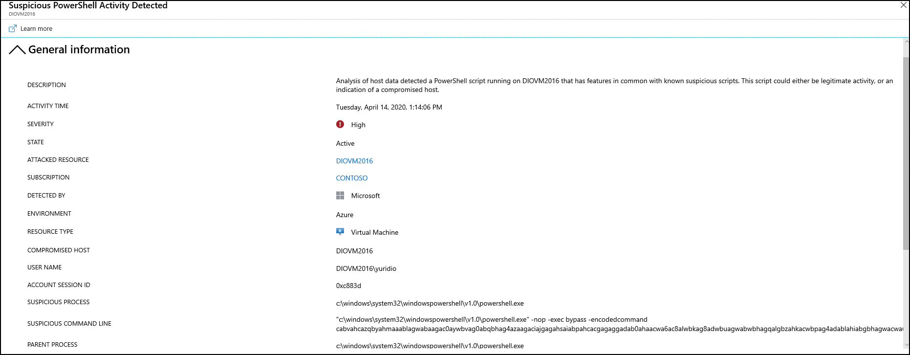
FIGURE 2-59 Example of a VM threat detection in Defender for Servers
Defender for Cloud will trigger a recommendation when it identifies VMs that don’t have disk encryption enabled. Another aspect of VM security is the identification of resource abuse. When VM processes consume more resources than they should, this could also be an indication of suspicious activity. Without a doubt, performance issues could happen for a variety of issues, including an application that was not well-written. Performance issues might also happen because the VM is running out of resources because the valid load is high. (In this case, you need to upgrade the VM with more resources.) Whatever the cause may be, the bottom line is that a VM’s performance can lead to service disruption, which directly violates the security principle of availability.
You can use Azure Monitor to obtain visibility of your VM’s health. By leveraging Azure Monitor’s features, such as resource diagnostic log files, you can identify potential issues that might compromise performance and availability. Azure Monitor and diagnostic logging are covered in more detail in Chapter 3, “Manage security operations.”
Implement and manage security updates for VMs
Keeping the system up to date is another imperative measure for any organization that wants to implement host security. The good news is that in Azure, you have two major services that can be used to ensure that your VMs are fully up to date.
Consider a scenario where you need to manage operating system updates for your Windows and Linux VMs, not only in Azure but also on-premises and in any other cloud environment. You can use the Update Management solution in Azure Automation to manage your VMs. Following are the components used by Update Management:
Log Analytics agent for Windows or Linux This is the same agent used by Defender for Cloud, which means you should have it already installed if you are using Defender for Cloud.
PowerShell Desired State Configuration (DSC) for Linux The management platform in PowerShell running on Linux.
Automation Hybrid Runbook Worker Each Windows machine that is managed by the solution is listed in the Hybrid worker groups.
Microsoft Update or Windows Server Update Services (WSUS) for Windows machines The update management platform managed by Microsoft (Microsoft Update) or managed by your organizations (WSUS).
Update management collection is done via a scan that is performed twice per day for each managed Windows server (clients are not supported) and every hour for Linux machines. The following versions of the operating systems are supported by this solution:
Windows Server 2019 (Datacenter/Datacenter Core/Standard)
Windows Server 2016 (Datacenter/Datacenter Core/Standard)
Windows Server 2012 R2 (Datacenter/Standard)
Windows Server 2012
Windows Server 2008 R2 RTM and SP1 Standard (assessment only, patching is not supported)
CentOS 6, 7, and 8
Red Hat Enterprise 6, 7, and 8
SUSE Linux Enterprise Server 12, 15, and 15.1
Ubuntu 14.04 LTS, 16.04 LTS, 18.04 LTS, and 20.04 LTS
You can enable the Update Management solution directly from the VM’s properties, which is a good approach if you only need to enable this solution for one VM. If you need to deploy to all VMs, you can select all VMs at once from the Virtual Machines dashboard and deploy to all VMs from there. VMs can be spread across up to three resources groups when enabling this solution for multiple VMs. Follow these steps to enable this feature for multiple VMs:
Navigate to the Azure portal at https://portal.azure.com.
In the search bar, type virtual machine, and under Services, click Virtual Machines.
Click the check box next to the field Name to select all VMs.
Click the Services button and click Update Management; the Enable Update Management page appears, as shown in Figure 2-60.
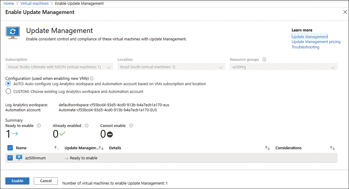
FIGURE 2-60 Enabling Update Management for VMs
Notice that the default configuration has the AUTO option selected. This option will auto-configure Log Analytics workspace and automation account based on your VM's subscription and location. If you already have VMs deployed with the Log Analytics and the agent is already configured to report to a specific workspace, the auto-configuration won’t work; you need to select CUSTOM and from there select the workspace where the VM resides as well as the Azure automation account that will be used by Updated Management.
For this example, leave the default selection and click the Enable button.
The deployment of this solution can take some time, depending on the amount of VMs that you select; wait until it is fully finished before proceeding.
Managing updates
Now that the Update Management solution is deployed to your VMs, you can access its dashboard to visualize the list of missing updates and scheduled update deployments. To access the Update Management dashboard, use the following steps:
Navigate to the Azure portal at https://portal.azure.com.
In the search bar, type automate, and under Services, click Automated Accounts.
Click the automation account that is used by your Update Management solution.
In the left pane, click Update Management, and if the scan is completed, the list of updates will appear, as shown in Figure 2-61.
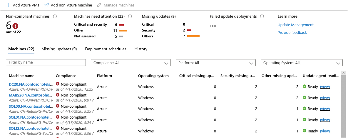
FIGURE 2-61 Update Management dashboard
Click the Missing Updates tab to visualize the updates that are currently missing on the machines (see Figure 2-62).

FIGURE 2-62 List of missing updates
In the example given in the previous steps, you saw an environment that was already in production, with machines already reporting to Update Management and a deployment schedule already created. In a new deployment, you will see that there is a Schedule Update Deployment button in the main Update Management dashboard, as shown in Figure 2-63.

FIGURE 2-63 Option to schedule the deployment of the updates
Configure security for containers services
Azure Container Registry (ACR) is a private registry of Docker and Open Container Initiative (OCI) images, based on open-source Docker Registry 2.0. Developers can pull (download) images from an Azure container registry, and they can also push (upload) to a container registry as part of a container development workflow. ACR pricing tiers are
Basic More suitable for developers learning about ACR
Standard Increased storage and image throughput and more suitable for a production environment
Premium More suitable for high-volume scenarios and high image throughput
You can use an Azure AD service principal to provide container image docker push and pull access to your container registry. Azure AD service principals provide access to Azure resources within your subscription. Think of a service principal as a user identity for a service.
Manage access to Azure Container Registry
To manage access to your Azure Container Registry (ACR) you must add a user to a specific role that will allow the user to perform certain tasks. Table 2-3 provides the mapping of the roles for the allowed tasks that can be executed in the ACR:
TABLE 2-3 Azure Container Registry RBAC roles
Role | Tasks that can be executed |
Owner | Access resource manager, create and delete the registry, push images, pull images, delete image data, and change policies |
Contributor | Access resource manager, create and delete the registry, push images, pull images, delete image data, and change policies |
Reader | Access resource manager and pull images |
ArcPush | Push and pull images |
ArcPull | Pull image |
ArcDelete | Delete image data |
ArcImageSigner | Sign images |
For CI/CD automation scenarios, you need docker push capabilities. For this type of scenario, we recommend that you assign the AcrPush role. This recommendation comes from the application of the principle of least privilege because this role, unlike the broader Contributor role, prevents the user from performing other registry operations or accessing Azure Resource Manager. Using the same rationale, nodes running containers need the AcrPull role but shouldn’t require Reader capabilities.
To pull or push images to an Azure container registry, a client must interact over HTTPS with two different endpoints: the Registry REST API endpoint and the storage endpoint. By default, an ACR accepts connections over the Internet from hosts on any network. If you are using ACR Premium, you can leverage Azure VNet network access rules to control access to your ACR.
When managing ACR, it is a good practice to implement a vulnerability assessment solution that scans all pushed images. You can leverage Microsoft Defender for Containers to have the vulnerability assessment functionality.
When this capability is enabled, Microsoft Defender for Containers scans the image that was pushed using a Qualys scanner, which is fully integrated with the Microsoft Defender for Containers, and there is no additional cost for the Qualys engine. Figure 2-64 shows a diagram of how vulnerability management for ACR is done using Microsoft Defender for Containers.
If an issue is found during this scanning process, Microsoft Defender for Containers generates an actionable recommendation that appears in Microsoft Defender for Cloud dashboard with guidance for remediating the issue. Figure 2-65 shows an example of the type of recommendations you might see.

FIGURE 2-64 Vulnerability scanning process in Defender for Containers
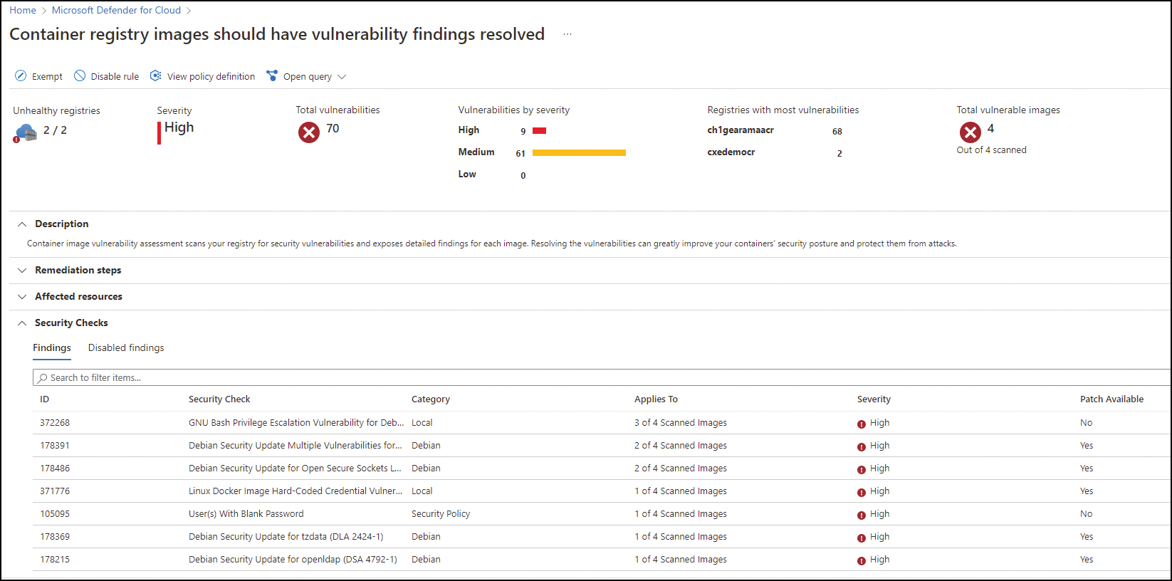
FIGURE 2-65 Container registry image recommendation in Microsoft Defender for Cloud
Configure security for serverless compute
A growing type of serverless compute is Azure Kubernetes (AKS), and when it comes to security for Kubernetes, one of the first aspects you need to address is isolation. This isolation is applicable for scenarios that you need to isolate workloads or teams. AKS provides capabilities for multitenant clusters and resource isolation. Natively, Kubernetes already creates a logical isolation boundary by using a namespace, which is the logical group of resources (such as pods).
Also, the following Kubernetes features should be used in scenarios that require isolation and multitenancy:
Scheduling The AKS scheduler allows you to control the distribution of compute resources and to limit the impact of maintenance events. This component includes the use of features such as resource quotas and pod-disruption budgets.
Networking AKS networking enables you to leverage the network policy’s capability to allow or deny traffic flow to pods.
Authentication and authorization As mentioned earlier in the chapter, the use of RBAC and Azure AD integration is imperative to enhance the security of your authentication and authorization.
Other features These features include pod-security policies, pod-security contexts, scanning images, and runtimes for vulnerabilities.
There are two main types of isolation for AKS clusters: logical and physical. You should use logical isolation to separate teams and projects. Using logical isolation, a single AKS cluster can be used for multiple workloads, teams, or environments.
It is also recommended that you minimize the number of physical AKS clusters you deploy to isolate teams or applications. Figure 2-66 shows an example of this logical isolation.
Logical isolation can help minimize costs by enabling autoscaling and run only the number of nodes required at a time.
Physical isolation is usually selected when you have a hostile multitenant environment where you want to fully prevent one tenant from affecting the security and service of another. The physical isolation means that you need to physically separate AKS clusters. In this isolation model, teams or workloads are assigned their own AKS clusters. While this approach usually looks easier to isolate, it adds additional management and financial overhead.

FIGURE 2-66 AKS logical isolation
There are many built-in capabilities in AKS that help ensure that your AKS Cluster is secure. Those built-in capabilities are based on native Kubernetes features, such as network policies and secrets, with the addition of Azure components, such as NSG and orchestrated cluster upgrades.
The combination of these components is used to keep your AKS cluster running the latest OS security updates and Kubernetes releases, secure pod traffic, and provide access to sensitive credentials. Figure 2-67 shows a diagram with the core AKS security components.
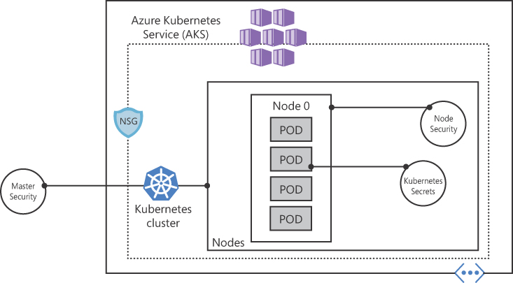
FIGURE 2-67 Core AKS security components
When you deploy AKS in Azure, the Kubernetes master components are part of the managed service provided by Microsoft. Each AKS cluster has a dedicated Kubernetes master. This master is used to provide API Server, Scheduler, and so on. You can control access to the API server using Kubernetes RBAC controls and Azure AD.
While the Kubernetes master is managed and maintained by Microsoft, the AKS nodes are VMs that you manage and maintain. These nodes can use Linux OS (optimized Ubuntu distribution) or Windows Server 2019. The Azure platform automatically applies OS security patches to Linux nodes on a nightly basis, but on Windows nodes, Windows Update does not automatically run or apply the latest updates. This means that if you have Windows nodes, you need to maintain the schedule around the update lifecycle and enforce those updates.
From the network perspective, these nodes are deployed into a private virtual network subnet with no public IP addresses assigned to it. SSH is enabled by default and should only be used for troubleshooting purposes because it is only available using the internal IP address. In Figure 2-67, you also have an NSG, which can also be used to enhance network protection.
AKS nodes use Azure Managed Disks, and the data is automatically encrypted at rest within the Azure platform. To fulfill the security principle of availability, these disks are also securely replicated within the Azure datacenter.
The diagram shown in Figure 2-67 shows the Kubernetes secret element, which is used to inject sensitive data into pods, such as credentials or keys. The use of secrets reduces the sensitive information that is defined in the pod or service YAML manifest. You can read more about secrets in Kubernetes at https://kubernetes.io/docs/concepts/configuration/secret.
In addition to the native capabilities in Kubernetes and Azure that were described previously, you can enhance the security posture of your AKS deployment by leveraging Microsoft Defender for Cloud recommendations.
Microsoft Defender for Cloud constantly monitors the AKS and Docker configurations and then generates security recommendations that reflect industry standards. In addition to that, if you use Microsoft Defender for Containers, you will also have threat detections that are created based on the continuous analysis of raw security events, such as network data and process creation and the Kubernetes audit log. Based on this information, Microsoft Defender for Containers will alert you if threats and malicious activity detected at the host and AKS cluster level. Figure 2-68 shows an example of an alert that notifies you about an exposure of Kubernetes services.
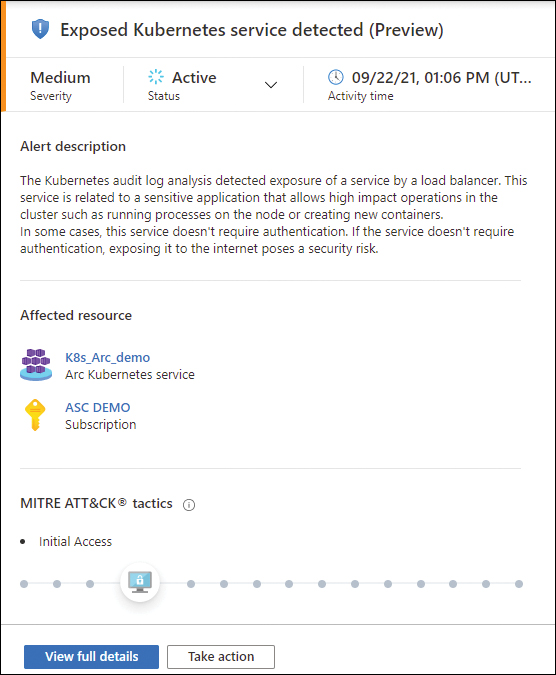
FIGURE 2-68 Alert for AKS generated by Defender for Containers
Configure security for Azure App Service
Azure App Service is an HTTP-based service for hosting web applications, REST APIs, and mobile back ends. Azure App Service Environment (ASE) is an Azure App Service feature that provides an isolated and dedicated environment for securely running App Service apps in the cloud. You can create multiple ASEs to host multiple apps running in Windows, Linux, Docker, mobile, and function apps.
To configure security for Azure App Service, you need to understand the variety of options available. Azure App Service has built-in security controls that can be leveraged to enhance the overall security posture of your apps. Essentially, some of these controls are Azure components that were described throughout this chapter. Table 2-4 provides a summary of the security controls that can be used with Azure App Service.
TABLE 2-4 Advantages and limitations
Layer | Security control | Description |
Network | Service Endpoint | You can use access restrictions to define a priority-ordered allow/deny list that controls network access to your app. This is an important practice to limit exposure to inbound network traffic. |
VNet injection support | This security control is used for ASE, which is a private implementation of App Service dedicated to a single customer and injected into that customer’s VNet. | |
Network Isolation and Firewalling support | You can configure network access control list (ACL) to lock down allowed inbound traffic. | |
Forced tunneling support | Although ASE outbound dependency traffic must go through the VIP that is provisioned with the ASE, you can configure it to customize the network routing. | |
Monitoring | Azure monitoring support | You can review quotas and metrics for an app and the App Service plan. You can also configure alerts and autoscale rules-based metrics. |
Control and management plane logging and audit | Because all management operations performed on App Service objects occur via Azure Resource Manager (ARM), you will be able to see historical logs of these operations. Keep in mind that there is no data-plane logging and auditing available for App Service. | |
Identity | Authentication | Supports integration with Azure AD and other OAuth providers. |
Authorization | Controlled by Azure AD and RBAC. | |
Data Protection | Server-side encryption at rest: Microsoft-managed keys | The App Service site file content is stored in Azure Storage, which automatically encrypts the content at rest, and the customer’s supplied secrets are encrypted at rest. |
Server-side encryption at rest: customer-managed keys (BYOK) | Supports the storage of an application’s secret in Key Vault, so that it can be retrieved during runtime. | |
Encryption in transit | Supports the use of HTTPS for inbound traffic. | |
API calls encrypted | Also supported via calls over HTTPS. | |
Configuration management | Configuration management support | The state of an App Service configuration can be exported as an ARM template. |
Besides the available security controls that are inherited from Azure, you should also ensure that you are always developing your apps using the latest versions of supported platforms, programming languages, protocols, and frameworks. It is very important that throughout the development lifecycle, you properly configure the authentication for these apps. Always make sure that authentication is required and that anonymous access is disabled unless the scenario’s description clearly states that it must be enabled. You can also enhance your authentication security by requiring clients to use a certificate to authenticate. This practice improves security by allowing connections only from clients that can authenticate using certificates that you provide.
As part of your secure configuration of App Service, make sure that data in transit is protected, which means that you should always redirect HTTP to HTTPS traffic and that you enforce the latest version of the TLS protocol. Communications from your Azure App Service and other Azure resources, such as Azure Storage, should also be encrypted. If the scenario description requires you to transfer files from your Azure app for another location using FTP, make sure that you are utilizing FTPS instead.
Some of the overall security recommendations for Azure App Service will also be surfaced in Microsoft Defender for Cloud, as shown in Figure 2-69.
Microsoft Defender for Cloud will perform this security assessment on your apps, which is part of the Microsoft Defender for Cloud security posture management. However, if you enable Defender for App Service plan, you will also get threat detection for App Service. Microsoft Defender for App Service threat detection includes analytics and machine-learning models that cover all interfaces that allow customers to interact with their applications, whether it’s over HTTP or through one of the management methods.
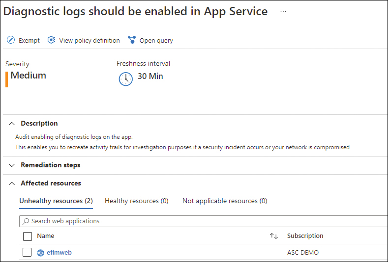
FIGURE 2-69 Defender for Cloud recommendations for App Service
To ensure your App Service is secure, you also need to address the authentication. By default, authentication and authorization are disabled. Upon enabling it, every incoming HTTP request passes through it before being handled by your application code. The authentication and authorization module runs separately from your application code and is configured using app settings.
The authentication and authorization modules are responsible for handling the authentication of users based on the selected provider, and it validates, stores, and refreshes tokens. They also manage the authenticated session and inject identity information into request headers. To configure authentication in App Service, you need to switch the App Service Authentication toggle to ON, and under Authentication / Authorization, the authentication options will appear, as shown in Figure 2-70.
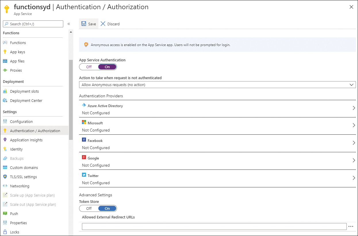
FIGURE 2-70 Authentication and authorization options
Because App Service uses federated identity in which a third-party identity provider manages the user identities and authentication flow, the next step is to configure the type of authentication provider that will answer to requests that are not authenticated. Click the Action To Take When Request Is Not Authenticated drop-down menu and select the appropriate option. The option that you selected in the drop-down menu should match with the provider that you select in the Authentication Providers section. Once you select the appropriate provider, its sign-in endpoint is available for user authentication and for validation of authentication tokens from the selected provider.
If you select the Allow Anonymous Requests (No Action) option in the drop-down menu, this option will defer authorization of unauthenticated traffic to your application code; in other words, you need to write the authentication code in your app. If it is an authenticated request, App Service will pass along authentication information in the HTTP headers. Table 2-5 shows a summary of each identity provider:
TABLE 2-5 App Service identity providers
Identity provider | Sign-in endpoint | Configuration requirements |
Azure AD | /.auth/login/aad | You can create a new Azure AD App or use an existing one. Allows you to enable Common Data Services (CDS) Permissions. |
Microsoft Account | /.auth/login/microsoftaccount | Requires the Client ID and Client Secret. You can select different scopes that are responsible for enabling different operations. |
/.auth/login/facebook | Requires the App ID and App Secret. You can select different scopes that are responsible for enabling different operations. | |
/.auth/login/google | Requires a Client ID and a Client Secret. | |
/.auth/login/twitter | Requires an API key and an API secret. |
If Contoso administrator’s requirement is to securely store and manage the data that is used by the company’s app, Azure AD is the identity provider that addresses this requirement because Azure AD allows you to use CDS.
Because App Service is a Platform as a Service (PaaS), the operating system (OS) and application stack are managed for you by Azure, which means you don’t need to worry about software updates. Azure manages OS patching on two levels: the physical servers and the guest VMs that run the App Service resources. Both will follow the regular Microsoft Patch Tuesday update cycle, which is once a month, unless it is a zero-day patch, which will be handled with higher priority and probably out of band (outside the regular Patch Tuesday cycle). When a new major or minor version is added to App Service, it is installed side by side with the existing versions.
App Service preserves its Service Level Agreement (SLA) even during the patch updates, which means that even if a patch requires a VM to restart, it will not affect App Service production because there always will be a buffer in capacity.
Access to patches in the registry at HKEY_LOCAL_MACHINESOFTWAREMicrosoftWindows CurrentVersionComponent Based ServicingPackages is locked down, though basic info regarding OS and runtime updates can be queried using Kudu Console at https://github.com/projectkudu/kudu/wiki/Kudu-console. For example, if you want to see the Windows version, you can access this URL: https://<appname>.scm.azurewebsites.net/Env.cshtml.
Configure encryption at rest
Data encryption at rest is an extremely important part of your overall VM security strategy. Defender for Cloud will even trigger a security recommendation when a VM is missing disk encryption. You can encrypt your Windows and Linux virtual machines’ disks using Azure Disk Encryption (ADE). For Windows OS, you need Windows 8 or later (for client) and Windows Server 2008 R2 or later (for servers).
ADE provides operating system and data disk encryption. For Windows, it uses BitLocker Device Encryption; for Linux, it uses the DM-Crypt system. ADE is not available in the following scenarios:
Basic A-series VMs
VMs with a less than 2 GB of memory
Generation 2 VMs and Lsv2-series VMs
Unmounted volumes
ADE requires that your Windows VM has connectivity with Azure AD to get a token to connect with Key Vault. At that point, the VM needs access to the Key Vault endpoint to write the encryption keys, and the VM also needs access to an Azure storage endpoint. This storage endpoint will host the Azure extension repository as well as the Azure storage account that hosts the VHD files.
Group policy is another important consideration when implementing ADE. If the VMs for which you are implementing ADE are domain joined, make sure to not push any group policy that enforces Trusted Platform Module (TPM) protectors. In this case, you will need to make sure that the Allow BitLocker Without A Compatible TPM policy is configured. Also, BitLocker policy for domain-joined VMs with custom group policy must include the following setting: Configure User Storage Of BitLocker Recovery Information / Allow 256-Bit Recovery Key.
Because ADE uses Azure Key Vault to control and manage disk encryption keys and secrets, you need to make sure Azure Key Vault has the proper configuration for this implementation. One important consideration when configuring your Azure Key Vault for ADE is that they (VM and Key Vault) both need to be part of the same subscription. Also, make sure that encryption secrets are not crossing regional boundaries; ADE requires that the Key Vault and the VMs are co-located in the same region. When configuring your Azure Key Vault, use Set- AzKeyVaultAccessPolicy with -EnabledForDiskEncryption to allow Azure platform to access the encryption keys or secrets in your key vault, as shown here:
Set-AzKeyVaultAccessPolicy -VaultName "<your -keyvault-name>" -ResourceGroupName
"MyResourceGroup" -EnabledForDiskEncryption
While these are the main considerations for Windows VM encryption, Linux VMs have some additional requirements. When you need to encrypt both data and OS volumes where the root (/) file system usage is 4 GB or less, you will need to have at least 8 GB of memory. However, if you need to encrypt only the data volume, the requirement drops to 2 GB of memory. The requirement doubles if Linux systems are using a root (/) file system greater than 4 GB, which means that the minimum memory requirement is root file system usage * 2.
Assuming that you have the right prerequisites in place to implement ADE, you can use the Set-AzVmDiskEncryptionExtension PowerShell cmdlet to implement the encryption in a VM, as shown in the following example:
$AKeyVault = Get-AzKeyVault -VaultName MyAKV -ResourceGroupName MyRG
Set-AzVMDiskEncryptionExtension -ResourceGroupName MyRG -VMName MyVM
-DiskEncryptionKeyVaultUrl $AKeyVault.VaultUri -DiskEncryptionKeyVaultId $AKeyVault.
ResourceId
Wait a few minutes, and the output will show the field IsSuccessStatusCode as True, and the StatusCode as OK. You can also check the encryption status using Get-AzVmDiskEncryption Status cmdlet. If it was encrypted successfully you should see a result similar to this:
OsVolumeEncrypted          : Encrypted
DataVolumesEncrypted       : NoDiskFound
OsVolumeEncryptionSettings : Microsoft.Azure.Management.Compute.Models.
DiskEncryptionSettings
ProgressMessage            : Provisioning succeeded
Configure encryption in transit
To ensure that you are always protecting the data in transit, you should configure your App Service to use an SSL/TLS certificate. To create a TLS bind of your certificate to your app or enable client certificates for your App Service app, your App Service plan must be configured to the Basic, Standard, Premium, or Isolated tiers.
The App Service enables different scenarios to handle certificates, which include the capability to buy a certificate; import an existing certificate from the App Service; upload an existing certificate that you might have already; import a certificate from Key Vault (from any subscription on the same tenant); or create a free App Service custom certificate. (This last option does not provide support for naked domains.)
With the exception of buying a certificate—which is available via the Buy Certificate button—all other options are surfaced under the Private Key Certificates (.pfx) tab in the TLS/SSL Settings option in the right-hand navigation pane of the App Service that you selected. Figure 2-71 shows an example of this tab.

FIGURE 2-71 Options to configure a private key certificate for App Service
For the purpose of the AZ-500 exam, the scenario description is what leads you to choose one option over the other. For example, let’s say that a Contoso administrator needs to secure data in transit for their App Service, but the administrator needs to save costs, leverage the existing Public Key Infrastructure (PKI) on-premises, and support naked domains. In this case, the most appropriate option would be to upload an existing certificate. This will save costs because it will leverage the existing PKI (which already met the second requirement), and it supports naked domains. When uploading an existing certificate, make sure you have the password for the protected PFX file; the private key must be at least 2048 bits long, and it must contain all intermediate certificates in the certificate chain.
Another important scenario is when you need to respond to requests to a specific hostname over HTTPS. In this case, you need to secure a custom domain in a TLS binding. In this scenario, you would use the Add TLS/SSL Binding option, which is available in the Bindings tab, as shown in Figure 2-72.

FIGURE 2-72 Options to add a TLS/SSL binding
The certificate that will be used to bind TLS/SSL needs to contain an ExtendedKeyUsage for server authentication object identifier (OID), which is 1.3.6.1.5.5.7.3.1, and it must be signed by a trusted certificate authority. Also, notice that on this page, you can also configure your App Service to only answer to HTTPS, and you can configure the TLS version that will be used.
Thought experiment
In this thought experiment, demonstrate your skills and knowledge of the topics covered in this chapter. You can find answers to this thought experiment in the next section.
Advanced security for compute at Tailwind Traders
You are one of the Azure administrators for Tailwind Traders, an online general store that specializes in a variety of products for the home. Tailwind Traders is deploying new VMs in Azure to increase the compute capacity because the company is forecasting an increase in online store shopping during the upcoming holiday season. Before releasing those VMs for use, they need to ensure that these VMs are configured to use security best practices, which include secure configurations, endpoint protection installation, and ensuring that the operating system is fully up to date.
Currently, Tailwind Traders does not have any cloud security posture management in place, but the company is interested in trying Microsoft Defender for Cloud. To improve security, they also need to continuously monitor those servers to identify potential attacks, and they want to receive an alert in case there are suspicious activities or indications of an attack against those servers. Another goal of Tailwind Traders is to allow the Security Operation Center (SOC) analysts to have read-only access to the Defender for Cloud dashboard in order to view the alerts. With this information in mind, answer the following questions:
Will Microsoft Defender for Cloud meet those requirements?
What Azure role should the SOC analysts have to accomplish their goals?
Where in Microsoft Defender for Cloud should the administrator go to identify whether the servers have an endpoint protection solution installed?
Thought experiment answers
This section contains the solution to the thought experiment. Each answer explains why the answer choice is correct.
Microsoft Defender for Cloud will only accomplish partial results of the desired requirements. It will enable the administrator to see security recommendations and improve the security posture of the workloads, but to have continuous monitoring of threat detection, the administrator needs to enable Microsoft Defender for Servers.
You should assign Security Reader role to the SOC analysts.
To identify whether the servers have an endpoint protection solution installed, you should go to the Recommendations dashboard in Microsoft Defender for Cloud.
Chapter summary
There are different types of Azure VPNs that will be selected according to the organization’s requirement, including site-to-site VPN, point-to-site VPN, VNet-to-VNet, and multi-site VPN.
Consider using ExpressRoute if your connectivity scenario requires a higher level of reliability, faster speeds, consistent latencies, and higher security than typical Internet connections.
Network security group (NSG) in Azure allows you to filter network traffic by creating rules.
Consider using Azure Firewall when your organization requires a fully stateful firewall, centralized management, with network- and application-level protection.
Consider using Azure Front Door when your organization’s requirements include Azure deployment across different regions with a high-performance experience for applications and that it is resilient to failures.
When you need resource-level filtering to enhance the security of your workloads, make sure to use a resource-level firewall.
Enable Azure DDoS Standard when you need to tune application traffic volume, and you want to ensure an SLA level that provides application guarantee and cost protection.
To receive threat alerts in Microsoft Defender for Cloud, you need to enable a Microsoft Defender for Cloud plan for the appropriate workload.
You can use Microsoft Defender for Cloud to monitor the security posture of Azure Kubernetes and Azure Container registry.
Azure Disk Encryption requires that your Windows VM has connectivity with Azure AD to get a token to connect with Key Vault.
To ensure that you are always protecting the data in transit, you should configure your App Service to use an SSL/TLS certificate.