

IBM zAware installation
This chapter describes our experiences with installing IBM zAware. The detailed installation information is provided in IBM System z Advanced Workload Analysis Reporter (IBM zAware) Guide, SC27-2623. However, providing a working example can be helpful in guiding you through the installation steps.
This chapter describes all the steps involved, from the beginning of the installation process through the point where historical message data is loaded into IBM zAware.
Specifically, the following topics are discussed:
•Overview of the installation
•Customizing the LPAR activation profile
•Sample network configuration
•Security considerations
•Setting up System Logger
•Connecting to the IBM zAware server
•Running the bulk load client
4.1 Overview of the IBM zAware installation process
This chapter provides an overview of the steps involved in installing IBM zAware, followed by a description of our experience. To give an idea of the effort involved and the elapsed time, our installation was completed in slightly over half a day. Spending a little more time on advanced planning, particularly in the network area, would have allowed us to complete the installation in less than half a day.
To understand the information that IBM zAware bases its analysis on, it is important to be familiar with z/OS message flow because that determines which messages IBM zAware will see. When a Write To Operator (WTO) message is issued, it goes through Message Processing Facility (MPF) and Message Flood Automation (MFA) processing, and is queued to a message data space, as shown in Figure 4-1. The message is then delivered to MCS consoles, SYSLOG, OPERLOG, and so on.
When a message is sent to OPERLOG, and the OPERLOG log stream is defined with the appropriate attributes, System Logger queues the message to be sent to IBM zAware. Therefore, you need to customize System Logger, the OPERLOG log stream definition, and TCP/IP settings to enable the flow of messages from OPERLOG to IBM zAware.
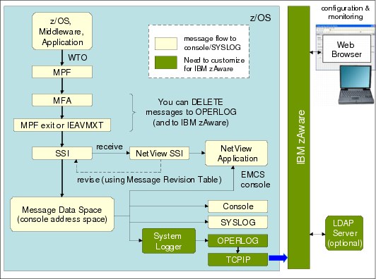
Figure 4-1 Overview of z/OS message flow
When the message data is received in the IBM zAware LPAR, IBM zAware analyzes the message and reports anomalous message behavior. You can view the analysis results on the IBM zAware GUI using your web browser. You need to customize the IBM zAware LPAR setting and the security environment to control access to the IBM zAware server.
Installing IBM zAware involves several steps. Each step is covered in detail in the following sections.
IBM zAware LPAR
Configuring the IBM zAware server involves the following four main steps:
1. Update your hardware configuration.
Use HCD to update your hardware definition to include the IBM zAware LPAR and its storage and network devices.
2. Customize an Activation Profile.
Before you can perform any customization on IBM zAware, you must define the image profile of the IBM zAware LPAR. You need to update the following tabs in the image profile on the HMC:
– General
– Processor
– Storage
– Firmware
To define this as an IBM zAware LPAR, you select the LPAR mode of “zAware” on the “General” tab. Then you specify how many processors and how much memory you assign for IBM zAware, and use the “Firmware” tab to provide the network information that enables IBM zAware to communicate with your browser and the systems that it will monitor.
3. Activate the IBM zAware LPAR.
After you customize an Activation Profile, you can activate the IBM zAware LPAR. It takes a few minutes for the LPAR to initialize.
4. Configure the IBM zAware server.
After the IBM zAware LPAR is activated successfully, you can access the IBM zAware server through your web browser. Before IBM zAware can perform any analysis, you must define storage devices for the IBM zAware server using the administration menu in the IBM zAware GUI.
Network
To deliver the message data from the monitored systems, you need to define network devices for the IBM zAware LPAR in the IOCDS. You also need to customize the TCP/IP profile and the hosts file of monitored systems to support the connection to the IBM zAware server.
Security considerations
This step includes two main sets of actions:
1. RACF definitions for System Logger
You need to set up the authority that the z/OS System Logger requires to send data to the IBM zAware server. You also need to define the SAF accesses that are required for the z/OS Bulk Data Load Utility.
2. User Authentication for the IBM zAware GUI
You define users to access the IBM zAware server through a local file-based repository or an LDAP directory. The “Role Mapping” menu on the IBM zAware GUI is used to distinguish between IBM zAware users and administrators.
Prepare System Logger
To prepare System Logger for use with IBM zAware, you must update the OPERLOG log stream definition in the Logger CDS. You also need to define new parameters in the IXGCNFxx Parmlib member for System Logger to have the information it requires to be able to connect to IBM zAware.
Connect
After you finish the previous steps you can connect monitored systems to the IBM zAware server by issuing System Logger SETLOGR commands. You can also check the status using System Logger DISPLAY commands and the IBM zAware GUI.
Run the Bulk Data Load Utility
To build a realistic model of normal system behavior, IBM zAware requires message data for a representative period of time. In general, 90 days of message data (from syslog or OPERLOG archives) should be sufficient to let IBM zAware build its model. You use the Bulk Data Load Utility to send the historical message data to the IBM zAware server. Before running the Bulk Data Load Utility, however, you need to establish the TCP/IP connection from the system to the IBM zAware server.
From the viewpoint of the IBM zAware installation, the definitions that must be updated to start the IBM zAware analysis are listed in Table 4-1.
Table 4-1 Definitions for IBM zAware
|
Component
|
Definition
|
Where to define
|
Reference
|
|
IOCDS
|
IBM zAware LPAR
|
HCD or
IOCP and HMC
|
|
|
Storage devices
|
|||
|
Channel paths
|
|||
|
Activation Profile
|
Image Profile
|
HMC
|
|
|
IBM zAware server
|
Configuration
|
IBM zAware GUI
|
|
|
Training data
|
Monitored z/OS system and IBM zAware GUI
|
||
|
OPERLOG
|
OPERLOG log stream definition, CONSOLxx and so on
|
Monitored z/OS system
|
|
|
System Logger
|
Logger CDS
|
||
|
IXGCNFxx
|
|||
|
IEASYSxx
|
|||
|
RACF
|
|||
|
TCP/IP
|
Profile member
|
||
|
Hosts file
|
|||
|
User Security
|
Authority to access to the IBM zAware GUI
|
IBM zAware GUI, Security product
|
4.2 IBM zAware LPAR
Setting up the hardware configuration definitions for the IBM zAware LPAR includes the following activities:
1. Define the IBM zAware LPAR and devices in your IOCDS.
To start, make sure that the IBM zAware LPAR is defined in the IOCDS. Also, the storage devices that the IBM zAware server will use must be defined, and the IBM zAware LPAR needs to be in the access list of those devices.
As discussed in 3.3.3, “DASD storage” on page 102, we strongly advise that you set up an explicit device candidate list so that the only storage devices that the IBM zAware LPAR has access to are its own devices.
In this example we did not use an explicit device candidate list because ours was merely a test environment. However, in an actual production environment, such a list should definitely be used. Although slightly time-consuming to set up the first time, after the definitions are in place future maintenance should be straightforward.
In our configuration, we use an LPAR name of “A1A” and storage device numbers that range from 9487 to 9489 (Figure 4-2).
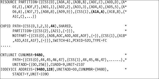
Figure 4-2 Example of the IOCP definition
You also need to define the network devices for the IBM zAware LPAR in your IOCDS. Figure 4-3 shows the sample IOCP definition of a QDIO OSA.

Figure 4-3 OSA definition for the IBM zAware LPAR in IOCP
Figure 4-4 shows the IBM HiperSockets™ definition statements. If the monitored clients and the IBM zAware LPAR are in the same zEnterprise Ensemble, you can use a channel path identifier of OSX for the IEDN. Make sure the IBM zAware LPAR is included in the access list.
The CHPIDs that are used for the OSA adapter and HiperSockets (00 and F4, in this case) will be specified when you set up the IBM zAware image profile on the HMC. All LPARs that will communicate with the IBM zAware LPAR using HiperSockets should be defined in the access list for that CHPID (F4).

Figure 4-4 HiperSockets definition for the IBM zAware LPAR in IOCP
2. Customize the IBM zAware LPAR Activation profile.
Before you activate the IBM zAware LPAR, you need to customize its Image profile. Select the IBM zAware LPAR and click Customize/Delete Activation Profiles task (Figure 4-5) on the HMC.
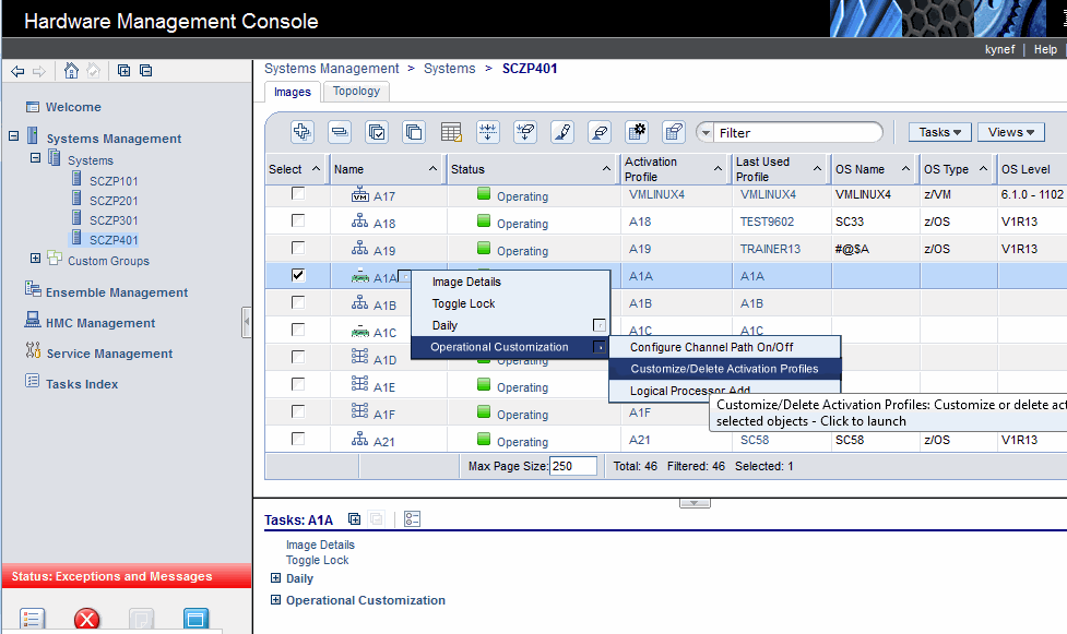
Figure 4-5 Select “Customize/Delete Activation Profiles” task
Select the image profile of the LPAR and click the Customize profile button as shown in Figure 4-6.
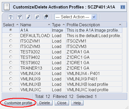
Figure 4-6 Customize profile
On the General tab, there is a new LPAR mode option of “zAware” for a zEC12 LPAR. Select zAware mode as shown in Figure 4-7.
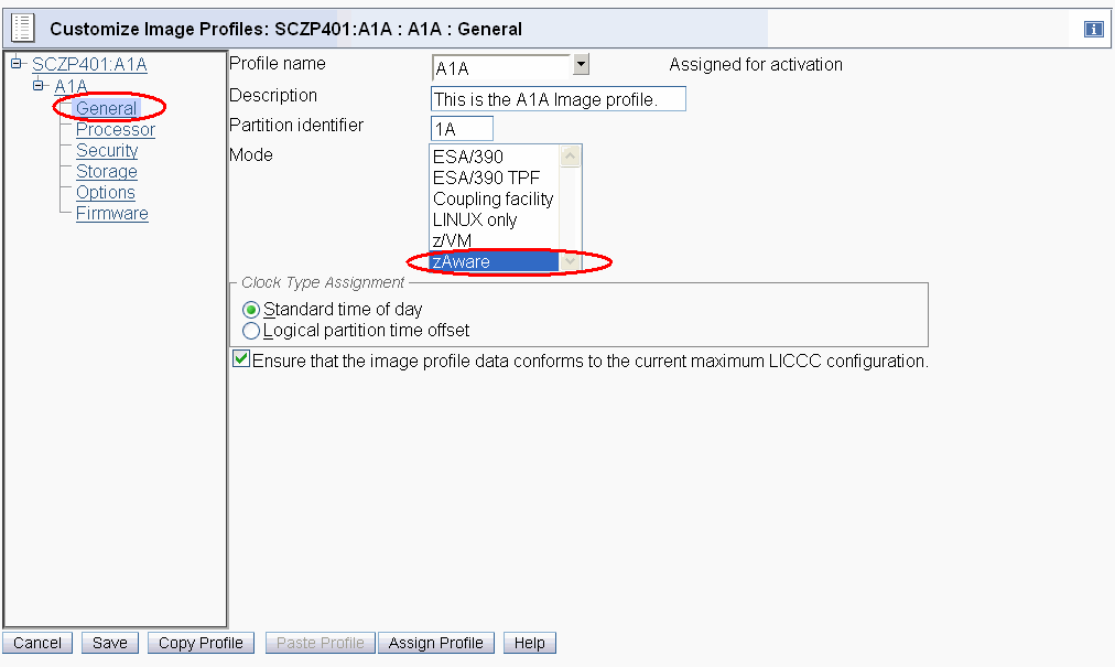
Figure 4-7 Customize General tab
After you select “zAware” mode, a new “Firmware” tab appears. On the Firmware tab, you need to define the network information for the IBM zAware server and a master user ID that has authority to perform any task that is available through the IBM zAware GUI. The definitions for other users who can access to the IBM zAware server will be done later, as described in 4.4, “Security considerations” on page 130.
Figure 4-8 on page 120 shows the values we used to set up our IBM zAware LPAR. In this example, the user ID is FRANK and there are two network adapters. Note that the user ID is not case-sensitive, but the password is case-sensitive. Work with your network colleagues to get the information you need to complete the Firmware tab.
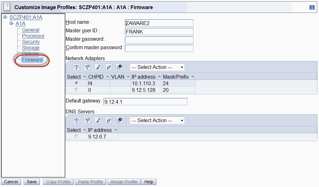
Figure 4-8 Customize Firmware tab
In this sample configuration, CHPID 00 is used for the OSA adapter and CHPID F4 is used for the HiperSockets connection. The CHPIDs used here must match those defined in the IOCDS.
The host name and IP address that you enter here might need to be defined in the z/OS hosts files on the monitored systems, as discussed in 4.3, “Network” on page 128.
On the “Processor” tab, you specify the processor assignment for IBM zAware (Figure 4-9). Select general purpose CPs or IFLs, and dedicated or non-dedicated. In our example, we defined our IBM zAware LPAR with one shared IFL.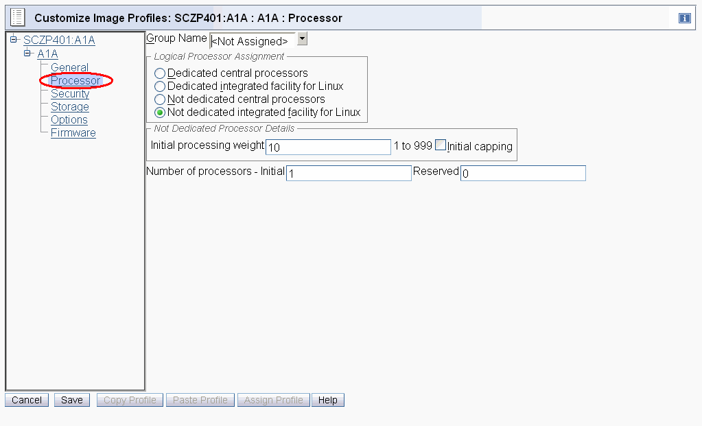
Figure 4-9 Customize Processor tab
On the “Storage” tab, you need to specify the amount of memory that you want to use for the LPAR. If you need to change the amount of memory available to the LPAR at a later time, you will need to deactivate and reactivate the IBM zAware LPAR.
To determine the required hardware resources for IBM zAware, check IBM System z Advanced Workload Analysis Reporter (IBM zAware) Guide, SC27-2623.
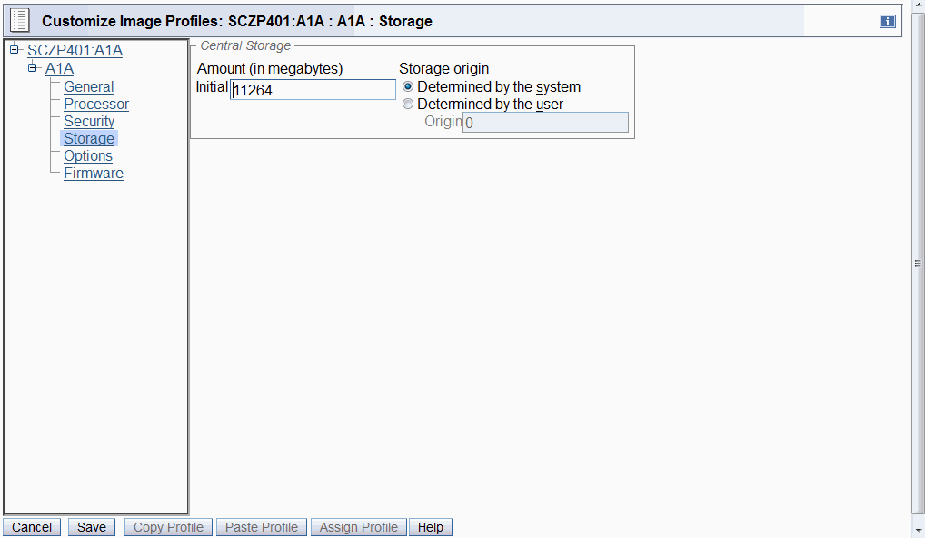
Figure 4-10 Customize Storage tab
3. Activate the IBM zAware LPAR.
To start the IBM zAware server, select the IBM zAware LPAR on the HMC and click Activate (Figure 4-11).
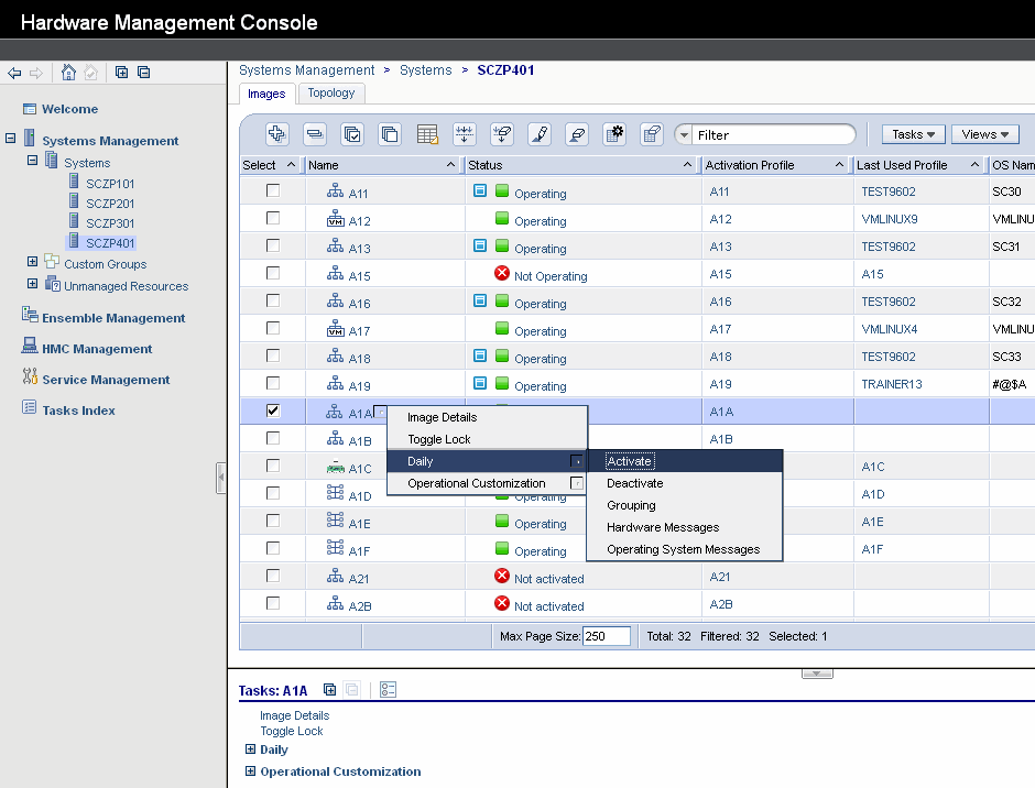
Figure 4-11 Activate the LPAR
The confirmation is displayed as shown in Figure 4-12. Confirm the information and click the Yes button.
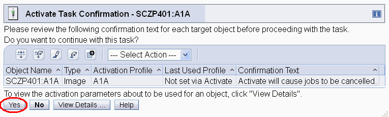
Figure 4-12 Perform Activate Task
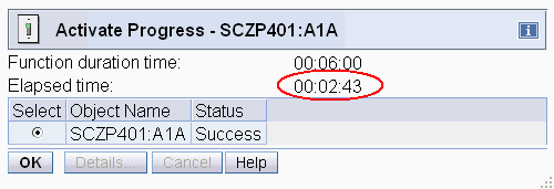
Figure 4-13 Complete LPAR activation
When the initialization completes, press OK and you will be returned to the list of LPARs. Confirm that the status of the LPAR is now Operating, as shown in Figure 4-14.
|
Tip: After the IBM zAware LPAR activates, it can take an additional few minutes for the WebSphere server to complete its initialization. Therefore, wait a few minutes before attempting to logon to IBM zAware.
|

Figure 4-14 Confirm the LPAR status
4. Configure the IBM zAware Server.
After the IBM zAware LPAR has been activated and you have given it a few minutes to complete its initialization, you should be able to log on the IBM zAware GUI. Enter the IP address or host name of the IBM zAware LPAR in your web browser. Use the “ip_address” or “host_name” that were specified on the Firmware tab of the image profile in the previous step:
Or use:
After you enter the address, the logon panel is displayed. Enter the Master user ID and password that you specified in the image profile (Figure 4-15); keep in mind that the password is case sensitive.
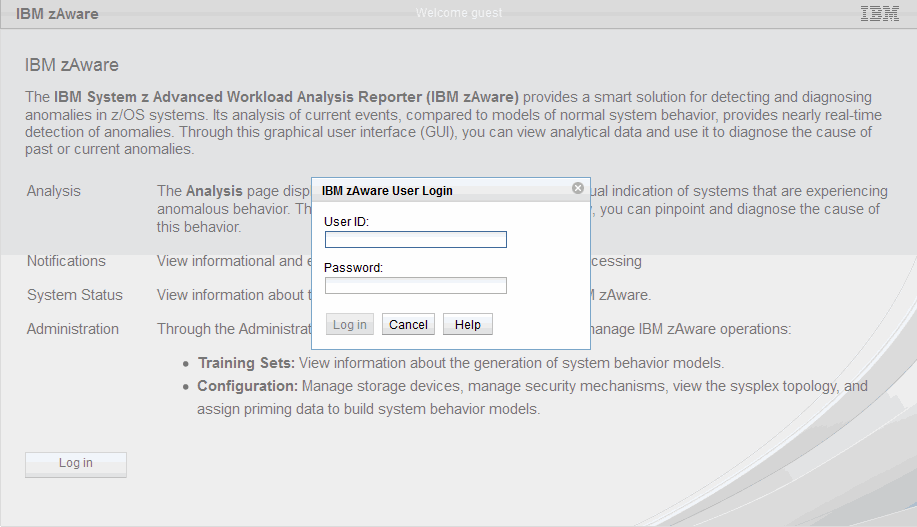
Figure 4-15 IBM zAware initial panel
When you log on the IBM zAware server for the first time, an error message is displayed as shown in Figure 4-16. You can ignore the message and click the OK button.

Figure 4-16 Warning information
To receive message data from the monitored systems and build the model, you need to configure the storage devices for the IBM zAware server. Select Administration → Configuration on the left menu.
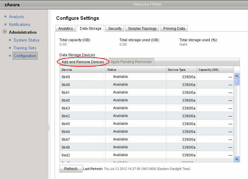
Figure 4-17 Add and Remove Devices
On the “Data Storage tab”, click the Add and Remove Devices tab at the top of the list of devices (see Figure 4-17 on page 125). This will bring you to another panel where you specify the storage devices that IBM zAware is to use.
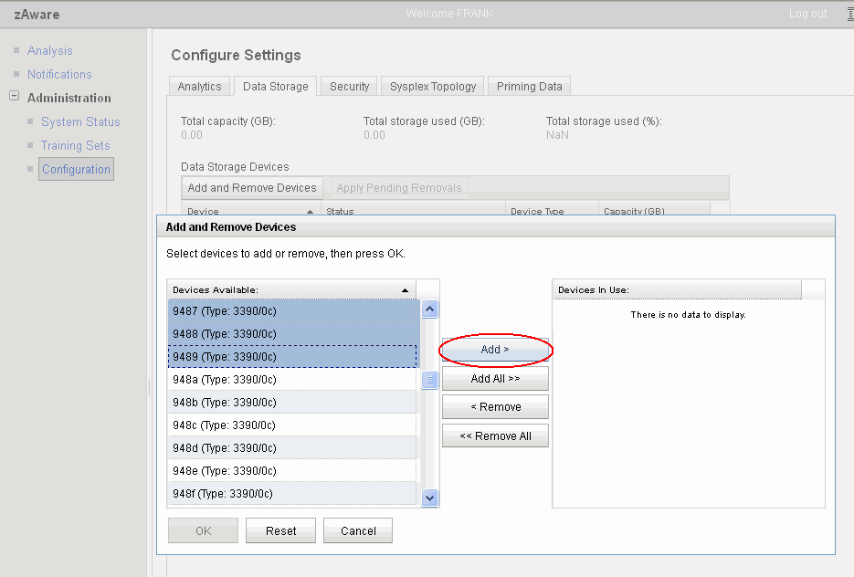
Figure 4-18 Select the devices
On the Add and Remove Devices panel, you can sort the list of devices by clicking the Devices Available heading. Select the devices you want to use and click the Add button as shown in Figure 4-18. As part of the process of adding a storage device, IBM zAware will always initialize that device.
|
Ensure that you select the correct devices: IBM zAware does not ask to you reconfirm the devices you select. Therefore, it is important to ensure that you select the correct devices.
To reduce the chance of accidentally initializing the wrong devices, set up the IBM zAware LPAR in HCD so that it can only access its own devices.
|
Confirm that the correct devices are now listed in the Devices in Use window on the right side. Then click the OK button as shown in Figure 4-19.
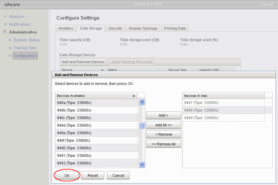
Figure 4-19 Add the selected devices
It might take several minutes to initialize each device, depending on the size of the volume. If the volume was previously used by IBM zAware, the initialization process will detect that and the initialization will take less time. Figure 4-20 shows that the device status changes to Being Added while the device is being initialized.
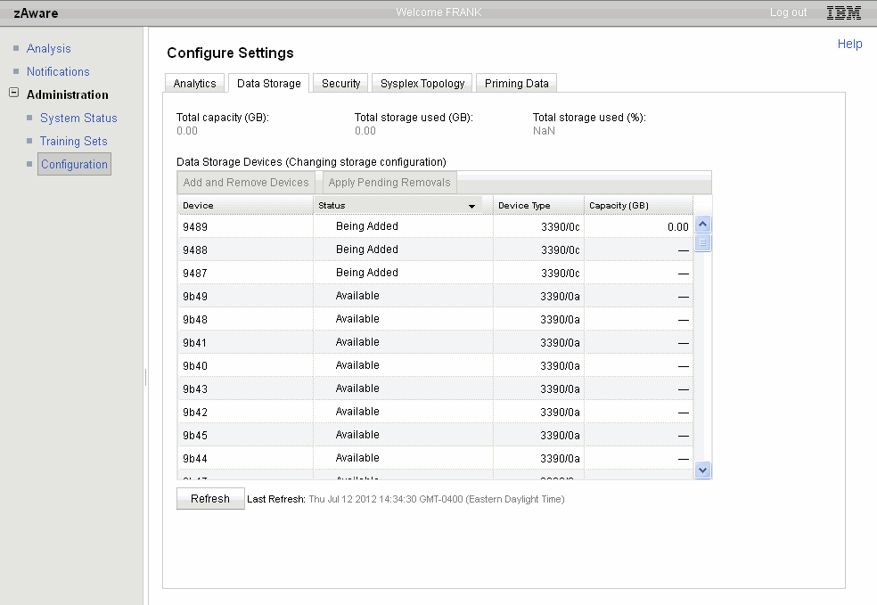
Figure 4-20 Device status sorted by status

Figure 4-21 The status of added devices
You can customize the “Analytics” and “Security” tabs on the Configuration menu at this point. However, now that you have the Master userID set up and some storage devices have been added to IBM zAware, it is not necessary to make those changes until later.
The “Analytics” tab in the Configuration Settings window is where you control how long IBM zAware is to retain various types of information in its database, and how often it is to train the systems. For now, it is probably best to use the default values provided by IBM. When you have more experience with IBM zAware, you might want to come back later and fine-tune those values. But remember that the values apply to all monitored systems; you cannot keep data for one system for 300 days and data from a different system for 600 days, for example.
The other tabs, such as “Analysis,” “System Status,” and “Training Sets” will not contain any information until you connect some systems to IBM zAware.
4.3 Network
To connect the monitored clients to the IBM zAware server, you can use HiperSockets, OSA adapters, or IEDN. In this section, we describe how we set up our network connections using HiperSockets and OSAs (see Figure 4-22 on page 129).
We use HiperSockets for the monitored systems that are in the same CPC as the IBM zAware LPAR, and OSAs for the systems in a different CPC.
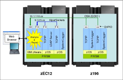
Figure 4-22 Sample network configuration
In this section we show sample TCP/IP settings for one of the monitored systems. The network configuration of the IBM zAware LPAR was defined on the image profile as shown in the previous step.
TCP/IP setting
To connect to the IBM zAware server you might need to customize the TCP/IP settings on the monitored z/OS systems. Figure 4-23 shows a sample profile definition for the OSA connection.
|
DEVICE OSA2400 MPCIPA
LINK OSA2400LNK IPAQENET OSA2400
....
HOME
9.12.4.xx OSA2400LNK
....
BEGINROUTES
ROUTE 9.12.4.0 255.255.252.0 = OSA2400LNK MTU 1500
ROUTE DEFAULT 9.12.4.1 OSA2400LNK MTU 1500
ENDROUTES
....
START OSA2400
|
Figure 4-23 Example TCP/IP profile for the QDIO OSA connection
If you add new OSA devices for the IBM zAware connection, you must also define the TRL major nodes in VTAMLST (see Figure 4-24) and activate them. The OSA devices need to be defined in the IOCDS and the IODF data set.
|
OSA2400 VBUILD TYPE=TRL
OSA2400P TRLE LNCTL=MPC, *
READ=2400, *
WRITE=2401, *
DATAPATH=(2402,2403,2404,2405), *
PORTNAME=OSA2400, *
MPCLEVEL=QDIO
|
Figure 4-24 Example TRL major node definition for the QDIO OSA connection
Figure 4-25 shows a sample definition for the HiperSockets connection. For this connection, you do not need to define a TRL major node.
|
DEVICE IUTIQDF4 MPCIPA NOAUTORESTART
LINK IUTIQDF4LNK IPAQIDIO IUTIQDF4
....
HOME
10.1.110.x IUTIQDF4LNK
....
GATEWAY
10 = IUTIQDF4LNK 1500 0.255.255.0 0.1.110.0
....
START IUTIQDF4
|
Figure 4-25 Example TCP/IP profile for the HiperSockets connection
To resolve the host name of the IBM zAware server you might need to update the local hosts file. Refer to z/OS Communications Server IP Configuration Guide, SC31-8775, to see how the host name is resolved in your environment. Figure 4-26 shows our example /etc/hosts file.
|
9.12.4.xx pst1.itso.ibm.com PST1
9.12.4.xx pst2.itso.ibm.com PST2
9.12.4.xx pst3.itso.ibm.com PST3
9.12.9.xxx msys.itso.ibm.com MSYS
10.1.110.x zaware2.itso.ibm.com zaware2
127.0.0.1 localhost
|
Figure 4-26 Example /etc/hosts file contents
4.4 Security considerations
This section includes the following topics:
•RACF definitions on the monitored systems
•User Authentication to use the IBM zAware GUI
4.4.1 RACF definition on the monitored systems
System Logger requires one or more of the following items:
•A UNIX System Service segment in its RACF user ID profile
This is required because System Logger will be using TCP/IP services through UNIX System Service.
•Being defined with a Trusted user ID
If this is done, no further accesses need to be granted to System Logger.
•Access to the SYSPLEX.OPERLOG log stream
•Access to the log stream that will be used by the bulk load utility
That log stream name is specified in the bulk data load job.
Additionally, the following people must have update access to the IXGZAWARE_CLIENT resource in the FACILITY class (this is a new resource, added as part of the IBM zAware support):
•The person who will run the job to modify the OPERLOG log stream definition to add the ZAI and ZAIDAAT attributes.
•The person who will define the model log stream that will be used by the Bulk Data Load job.
•The person who will run the bulk data load job.
– That person will also require authority to define new log streams because the bulk load job creates a model log stream.
– The person will also require read access to the syslog or OPERLOG archive data set containing the messages that are to be sent to IBM zAware.
For more information about the RACF considerations for System Logger resources, refer to “Define authorization to System Logger resources” in z/OS MVS Setting Up a Sysplex, SA22-7625.
4.4.2 User authentication to use the IBM zAware GUI
You can define the user authentication for the IBM zAware GUI by one or both of the following methods:
•Local file-based repository
•LDAP server directory
Select one strategy and define nearly all your user IDs in that repository; see “IBM zAware security” on page 109 for guidance about defining IBM zAware user IDs. If you use LDAP server, see 4.4.3, “LDAP setup” on page 134.
To manage your IBM zAware user IDs using the local file-based repository, logon to the WebSphere Integrated Solutions Console using the following address:
Enter the IBM zAware master user ID and password that you defined in the image profile for that LPAR, as shown in Figure 4-27 on page 132. User IDs and their roles are defined separately. The user ID is defined either in the local file-based repository or in LDAP. The role of each user ID (user or admin) is then defined using the IBM zAware GUI, as described in “Role mapping” on page 137.
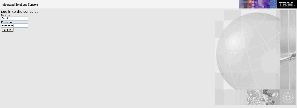
Figure 4-27 Logon panel of the Integrated Solutions Console
The Integrated Solutions Console is used to define user IDs in the local file-based repository. For example, to add a user, select Users and Groups → Manage Users on the left menu and click the Create button as shown in Figure 4-28.
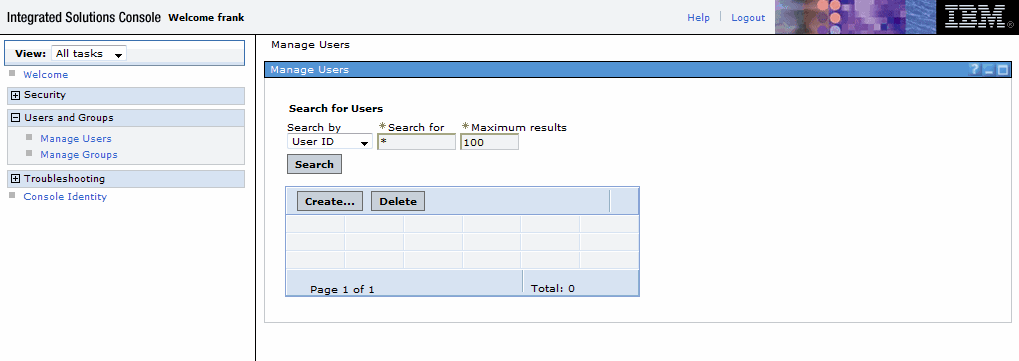
Figure 4-28 Manage Users window
On the Manage users window, enter the user ID, the person’s first name, last name, email address and a password. Click the Create button to add the user, as shown in Figure 4-29.
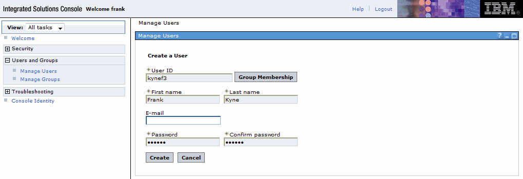
Figure 4-29 Creating a user ID
You can confirm that the user was added correctly using the Manage Users menu as shown in Figure 4-30.

Figure 4-30 Confirm an added user
To display the list of users, click the Search button on the Manage Users menu. Notice that the resulting list of user IDs includes users defined on the LDAP server (see Figure 4-31 on page 134).
You can determine which user IDs are defined in the local file-based repository, and which are defined in the LDAP server, by looking at the “Unique Name” associated with each user ID.
•User IDs that are defined in the file-based repository appear as shown here:
uid=frank,o=defaultWIMFileBasedRealm
•User IDs that are defined in LDAP appear as shown here:
uid=angela,ou=itso,o=ibm
To avoid confusion, it is best to manage all your user IDs in one repository or the other. Defining user IDs in both places increases the complexity of managing the user IDs.
|
Restriction: Although WebSphere supports multiple repositories for user ID definitions, it explicitly does not support defining the same user ID in more than one repository.
Doing so will result in unpredictable behavior, including the inability to use the user ID that is defined in both repositories.
|
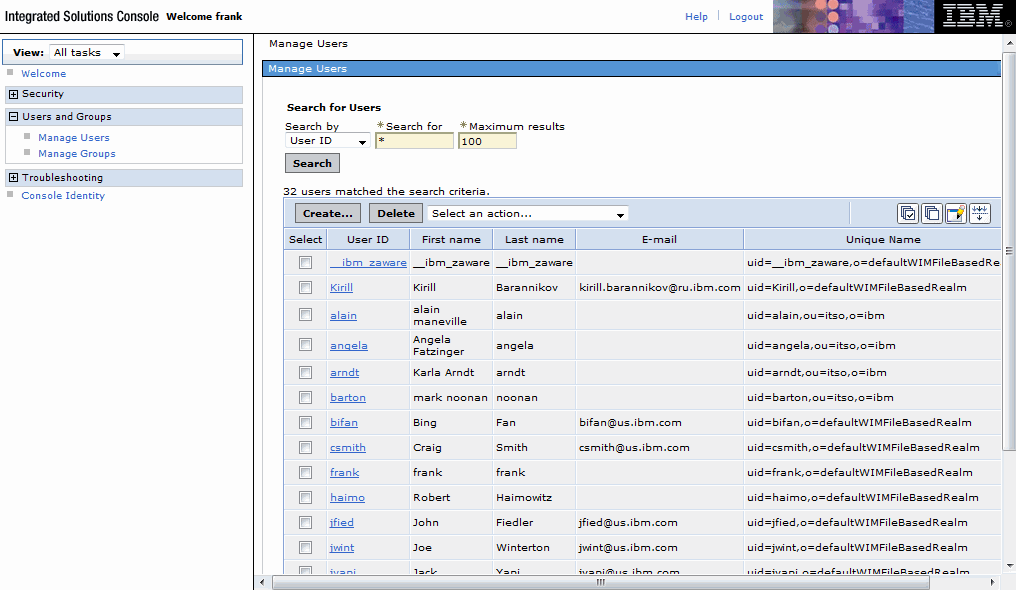
Figure 4-31 Displaying the list of users on the ISC console
IBM System z Advanced Workload Analysis Reporter (IBM zAware) Guide, SC27-2623 describes the local file-based security in more detail.
4.4.3 LDAP setup
LDAP data uses a tree structure of user information, as shown in Figure 4-32 on page 135. When IBM zAware is configured to use LDAP, the IBM zAware administrator can fetch user entries from the LDAP server and assign the IBM zAware security roles to the fetched users. After a user is assigned a security role, that user can then authenticate to the IBM zAware GUI using their LDAP entry and password.
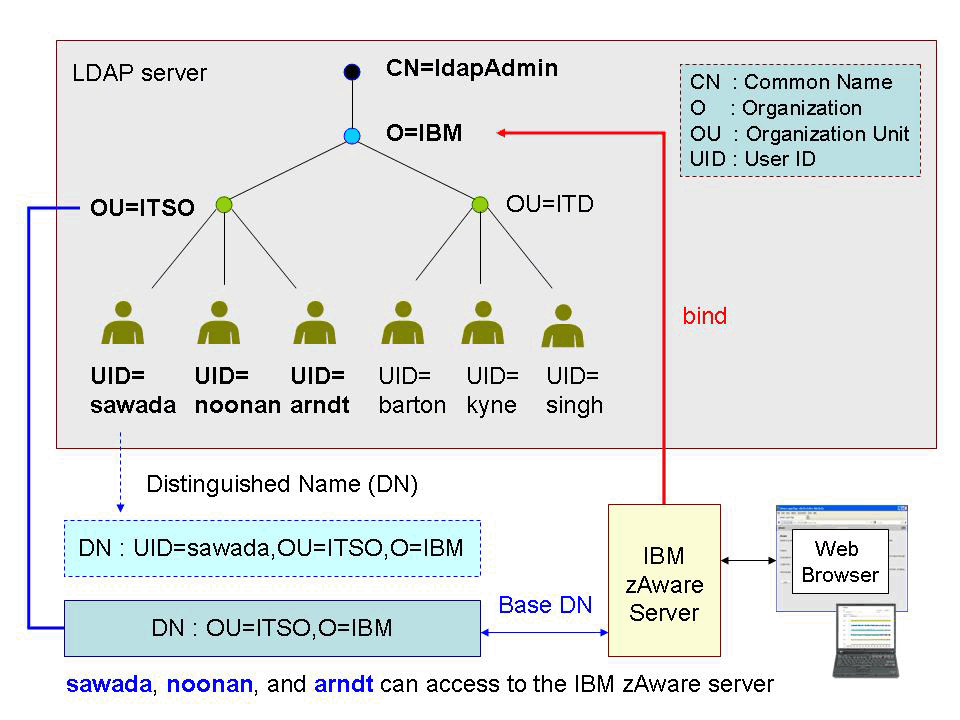
Figure 4-32 LDAP directory information tree
To fetch LDAP user entries, IBM zAware requires a valid bind distinguished name and bind password. The user entries that IBM zAware will fetch are determined by the Base distinguished name, login attribute and User object class fields that are specified in the LDAP Settings panel in the IBM zAware GUI.
After an LDAP user has been assigned a role, that user can then use its LDAP entry to authenticate to the IBM zAware GUI. IBM zAware will issue a bind to the LDAP server using the data entered by the user (ID and password) in the IBM zAware GUI login prompt. If the bind is successful, IBM zAware allows the user access.
The user ID that is entered in the IBM zAware User Login panel is determined by the Login attribute field of the LDAP Setting panel. For example, if the Login attribute field is set to UID and the user has an LDAP entry with the distinguished name of FRANK,ou=ITSO,O=IBM, then the user must use FRANK as the login name on the IBM zAware login prompt.
Figure 4-33 on page 136 and Figure 4-34 on page 137 show an example of the LDAP Settings window in the IBM zAware GUI.
You specify the host name and port number of an LDAP server to which IBM zAware will communicate with on the LDAP Settings tab within the Security tab on the IBM zAware GUI Configuration Options window. The “Bind distinguished name” and “Bind password” is the LDAP entry that IBM zAware will use to bind to LDAP for searches and retrieval of user entries. If you do not specify this information, the server binds anonymously. You also specify “Base distinguished name” to specify the portion of the LDAP directory tree for which IBM zAware will search for entries, the “Login attribute” which specifies what LDAP attribute will be used as the login attribute on the IBM zAware login prompt, and the “User object classes” to specify the type of LDAP objects that will be searched and retrieved by IBM zAware.

Figure 4-33 LDAP general information settings
If you are using LDAP groups, IBM zAware can also retrieve group objects from LDAP. Typically, LDAP groups contain a list of user distinguished names. For the group setting you are required to input “Group object class,” which specifies the type of group entry to retrieve, and “Group member attribute” information, which specifies the attribute within the group that represents the user entry.
If you manage users by groups, you also specify the “Group search bases,” which represent the portion of the directory tree to be searched, as shown in Figure 4-34.

Figure 4-34 LDAP group information settings
Updates to the LDAP Settings panel require a restart of the IBM zAware security server. After you enter the LDAP information and click the Apply button, the information panel is displayed as shown in Figure 4-35. Clicking OK and restarts the relevant IBM zAware process. Note that restarting the security server does not cause the connections to the monitored clients to be stopped.
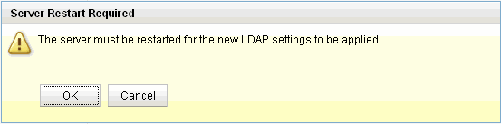
Figure 4-35 Server Restart Required window
The IBM zAware GUI Security tab is also where you assign (map) roles to defined users.
Role mapping
Users who access the IBM zAware GUI must be mapped to one of two roles. One is “administrator” and the other is “user”. An administrator user ID can perform all IBM zAware tasks, but a User user ID cannot use, or see, most of the items on the Administration menu.
To display the roles that are assigned to the defined user IDs, or to assign a role to a user ID, you must log on to the IBM zAware GUI using a user ID with administrator authority. The user ID that you defined in the LPAR’s image profile (known as the master user ID) is automatically defined as an administrator.
Select Administration → Configuration in the left-side menu and then click Role Mapping on the Security tab, as shown in Figure 4-36.

Figure 4-36 Role mapping menu
You can display the list of each type of user ID by clicking the Role drop-down and selecting either User or Administrator and then pressing the Search button. The resulting display shows a list of all defined users in the Available users box and the list of User or Administrator user IDs (depending on which option you selected) in the Current Mapped Users box (Figure 4-37).

Figure 4-37 Displaying the administrator user IDs
When you add a user ID and want to assign it a role, select the role that you want to assign to that user ID and click the Search button. Select the user ID to be added in the Available users box and click the Add button, as shown in Figure 4-38.

Figure 4-38 Assigning a role to a user ID
When you have finished selecting the user IDs that you want to change, click the Apply button to finalize the change for the user ID roles, as shown in Figure 4-39.
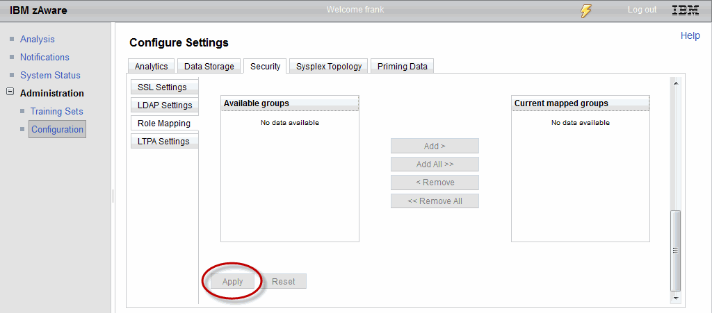
Figure 4-39 Apply the change of user role information
The IBM zAware security server must be restarted to apply the user ID role changes. After clicking the Apply button, a Server Restart Required window is displayed, as shown in Figure 4-40. When you click OK, the security server will restart automatically; this will take about one minute.
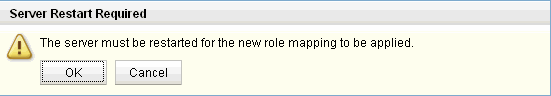
Figure 4-40 Server Restart Required window
4.5 Prepare System Logger
This topic describes the steps required to customize System Logger to send message data to the IBM zAware server.
Prepare OPERLOG
If you do not currently use OPERLOG, you must enable it on all systems that you want to monitor with IBM zAware. We do not cover setting up OPERLOG in this book. However, if you are not using OPERLOG, you can find information about setting it up in the IBM Redbooks document S/390 Parallel Sysplex: Resource Sharing, SG24-5666, and in z/OS MVS Setting Up a Sysplex, SA22-7625.
Update the OPERLOG log stream
After you set up OPERLOG, you need to update the OPERLOG log stream definition in the LOGR CDS to indicate that the information in that log stream should be sent to IBM zAware. Figure 4-41 shows a sample set of JCL to update the log stream definition.
|
//STEP1 EXEC PGM=IXCMIAPU
//SYSPRINT DD SYSOUT=*
//SYSABEND DD SYSOUT=*
//SYSIN DD *
DATA TYPE(LOGR) REPORT(YES)
UPDATE LOGSTREAM NAME(SYSPLEX.OPERLOG)
ZAI(YES)
ZAIDATA('OPERLOG')
|
Figure 4-41 Sample JCL to update LOGR CDS
Update IXGCNFxx parmlib member
You must also customize the System Logger Parmlib member (IXGCNFxx) to include the information required to connect to the IBM zAware server. Sample statements are shown in Figure 4-42.
|
/* IBM zAware Connection */
ZAI
SERVER(9.12.5.xxx)
PORT(2001)
LOGBUFMAX(2)
LOGBUFWARN(90)
LOGBUFFULL(MSG)
|
Figure 4-42 Sample IXGCNFxx member
|
Tip: Be sure to include the ZAI keyword on the line before the SERVER keyword.
|
To ensure that System Logger always comes up with the information it needs to connect to IBM zAware, make sure that your IEASYSxx Parmlib member points to the correct IXGCNFxx member, as shown in Figure 4-43.
If you do not specify IXGCNF=xx in the IEASYSxx member, the system will not default to IXGCNF00. You must explicitly state which IXGCNF member you want System Logger to use.
|
IOS=00,
IXGCNF=xx,
LPA=(&LPALST.),
|
Figure 4-43 Example of IEASYSxx member
You can also update System Logger dynamically to use this information using the following command:
SET IXGCNF=xx
You can use the same command to activate a change if you update any of the keywords in the IXGCNFxx member, or if you create a new member and want to switch to that one.
To verify that System Logger has the information it requires to connect to IBM zAware, issue the following command:
DISPLAY LOGGER,IXGCNF
|
D LOGGER,IXGCNF
IXG607I 15.11.06 LOGGER DISPLAY 899
LOGGER PARAMETER OPTIONS
KEYWORD SOURCE VALUE
----------------- -------- -------------------------------------------
....
ZAI
SERVER IPV4 SET (xx) 9.12.5.xxx
PORT SET (xx) 2001
LOGBUFMAX SET (xx) 02
LOGBUFWARN SET (xx) 90
LOGBUFFULL SET (xx) MSG
|
Figure 4-44 Response to DISPLAY LOGGER,IXGCNF command
To verify that the OPERLOG log stream definition has the correct attributes to be used with IBM zAware, issue the following command:
DISPLAY LOGGER,STATUS,ZAI
|
D LOGGER,STATUS,ZAI
IXG601I 15.34.03 LOGGER DISPLAY 643
SYSTEM LOGGER STATUS
SYSTEM SYSTEM LOGGER STATUS
------ --------------------
SC42 ACTIVE
ZAI LOGSTREAM CLIENTS: AVAILABLE
BUFFERS IN USE: 00 GB 0000 MB
LOGGER PARAMETER OPTIONS
KEYWORD SOURCE VALUE
----------------- -------- -------------------------------------------
ZAI
SERVER IPV4 IPL (xx) 9.12.5.xxx
PORT IPL (xx) 2001
LOGBUFMAX IPL (xx) 02
LOGBUFWARN IPL (xx) 90
LOGBUFFULL IPL (xx) MSG
|
Figure 4-45 Syslog output for DISPLAY LOGGER,STATUS,ZAI command
4.6 Connecting to IBM zAware
To connect to the IBM zAware server, issue the following command on each monitored system:
SETLOGR FORCE,ZAICONNECT,LSNAME=SYSPLEX.OPERLOG
|
SETLOGR FORCE,ZAICONNECT,LSNAME=SYSPLEX.OPERLOG
IXG651I SETLOGR FORCE ZAICONNECT COMMAND ACCEPTED 013
FOR LOGSTREAM=SYSPLEX.OPERLOG
IXG386I ZAI LOGSTREAM CLIENT CONNECT ATTEMPT IN PROGRESS 014
FOR LOGSTREAM SYSPLEX.OPERLOG
STATUS: ATTEMPTING SOCKET CREATE
IXG386I ZAI LOGSTREAM CLIENT CONNECT ATTEMPT IN PROGRESS 015
FOR LOGSTREAM SYSPLEX.OPERLOG
STATUS: SOCKET CREATE SUCCESSFUL
IXG386I ZAI LOGSTREAM CLIENT CONNECT ATTEMPT IN PROGRESS 016
FOR LOGSTREAM SYSPLEX.OPERLOG
STATUS: ATTEMPTING SOCKET CONNECT
IXG386I ZAI LOGSTREAM CLIENT CONNECT ATTEMPT IN PROGRESS 017
FOR LOGSTREAM SYSPLEX.OPERLOG
STATUS: SOCKET CONNECT SUCCESSFUL
IXG386I ZAI LOGSTREAM CLIENT CONNECT ATTEMPT IN PROGRESS 018
FOR LOGSTREAM SYSPLEX.OPERLOG
STATUS: INITIATING SOCKET VALIDATION
IXG386I ZAI LOGSTREAM CLIENT CONNECT ATTEMPT IN PROGRESS 019
FOR LOGSTREAM SYSPLEX.OPERLOG
STATUS: SOCKET VALIDATION SUCCESSFUL
IXG380I ZAI LOGSTREAM CLIENT ESTABLISHED 020
FOR LOGSTREAM SYSPLEX.OPERLOG
|
Figure 4-46 Response to SETLOGR FORCE,ZAICONNECT command
Note that if you issue the SETLOGR FORCE,ZAICONNECT command and there is already an active connection to the IBM zAware LPAR, the connection will be restarted. Any messages that are queued, waiting to be sent to the IBM zAware LPAR, will be retained. Transmission will continue when the connection restart completes.
You can check the connection status with the following command:
DISPLAY LOGGER,STATUS,ZAI,VERIFY
|
Command consideration: The DISPLAY LOGGER,STATUS,ZAI,VERIFY command establishes a connection with the IBM zAware server and changes the Instrumentation Data Type status (shown on the IBM zAware GUI) to null. If the connection to the IBM zAware LPAR is already active, using this command will cause that connection to be restarted.
The DISPLAY LOGGER,STATUS,ZAI,VERIFY command was designed to provide a test mechanism to ensure the network path to IBM zAware was available. Avoid using the VERIFY parameter if there is an active connection to IBM zAware.
|
|
D LOGGER,STATUS,ZAI,VERIFY
IXG386I ZAI LOGSTREAM CLIENT CONNECT ATTEMPT IN PROGRESS 181
FOR DISPLAY ZAI,VERIFY
STATUS: ATTEMPTING SOCKET CREATE
IXG386I ZAI LOGSTREAM CLIENT CONNECT ATTEMPT IN PROGRESS 182
FOR DISPLAY ZAI,VERIFY
STATUS: SOCKET CREATE SUCCESSFUL
IXG386I ZAI LOGSTREAM CLIENT CONNECT ATTEMPT IN PROGRESS 183
FOR DISPLAY ZAI,VERIFY
STATUS: ATTEMPTING SOCKET CONNECT
IXG601I 13.43.10 LOGGER DISPLAY 180
SYSTEM LOGGER STATUS
SYSTEM SYSTEM LOGGER STATUS
------ --------------------
SC43 ACTIVE
ZAI LOGSTREAM CLIENTS: ACTIVE
BUFFERS IN USE: 00 GB 0000 MB
ZAI VERIFY INITIATED, CHECK FOR MESSAGES IXG37X, IXG38X
LOGGER PARAMETER OPTIONS
KEYWORD SOURCE VALUE
----------------- -------- -------------------------------------------
ZAI
SERVER IPV4 SET (xx) 9.12.5.xxx
PORT SET (xx) 2001
LOGBUFMAX SET (xx) 02
LOGBUFWARN SET (xx) 90
LOGBUFFULL SET (xx) MSG
IXG386I ZAI LOGSTREAM CLIENT CONNECT ATTEMPT IN PROGRESS 184
FOR DISPLAY ZAI,VERIFY
STATUS: SOCKET CONNECT SUCCESSFUL
IXG386I ZAI LOGSTREAM CLIENT CONNECT ATTEMPT IN PROGRESS 185
FOR DISPLAY ZAI,VERIFY
STATUS: INITIATING SOCKET VALIDATION
IXG386I ZAI LOGSTREAM CLIENT CONNECT ATTEMPT IN PROGRESS 186
FOR DISPLAY ZAI,VERIFY
STATUS: SOCKET VALIDATION SUCCESSFUL
IXG380I ZAI LOGSTREAM CLIENT ESTABLISHED 187
FOR DISPLAY ZAI,VERIFY
|
Figure 4-47 Response to DISPLAY LOGGER,STATUS,ZAI,VERIFY command
You can verify that messages are being sent to IBM zAware from this system by issuing the following command:
DISPLAY LOGGER,C,LSN=SYSPLEX.OPERLOG,D
The response to this command is shown in Figure 4-48. The response confirms that the log stream is connected to IBM zAware. It also provides information about the number of log blocks that were sent successfully, and the number (if any) that failed.
|
D LOGGER,C,LSN=SYSPLEX.OPERLOG,D
IXG601I 13.43.33 LOGGER DISPLAY 189
CONNECTION INFORMATION BY LOGSTREAM FOR SYSTEM SC43
LOGSTREAM STRUCTURE #CONN STATUS
--------- --------- ------ ------
SYSPLEX.OPERLOG SYSTEM_OPERLOG 000002 IN USE
DUPLEXING: LOCAL BUFFERS
GROUP: PRODUCTION ZAI CLIENT: YES - CONNECTED
ZAIDATA: OPERLOG
LOG BLOCKS SENT TO SERVER OK: 0000006302, FAILED: 0000000000
JOBNAME: ZAWARE3 ASID: 0025
R/W CONN: 000001 / 000000
RES MGR./CONNECTED: *NONE* / NO
IMPORT CONNECT: NO
JOBNAME: CONSOLE ASID: 000B
R/W CONN: 000000 / 000001
RES MGR./CONNECTED: *NONE* / NO
IMPORT CONNECT: NO
NUMBER OF LOGSTREAMS: 000001
|
Figure 4-48 Response to DISPLAY LOGGER,C,LSN=SYSPLEX.OPERLOG,D command
If you need to disconnect the system from the IBM zAware LPAR, issue the following command:
SETLOGR FORCE,ZAIQUIESCE,LSNAME=SYSPLEX.OPERLOG
|
SETLOGR FORCE,ZAIQUIESCE,LSNAME=SYSPLEX.OPERLOG
IXG651I SETLOGR FORCE ZAIQUIESCE COMMAND ACCEPTED 727
FOR LOGSTREAM=SYSPLEX.OPERLOG
IXG382I ZAI LOGSTREAM CLIENT QUIESCED 728
FOR LOGSTREAM SYSPLEX.OPERLOG
REASON: SETLOGR COMMAND REQUEST.
IXG387I ZAI LOGSTREAM CLIENT CONNECTION SUMMARY 729
FOR LOGSTREAM SYSPLEX.OPERLOG
CONNECTION WAS ESTABLISHED AT: 07/17/2012 14:43:46 GMT
LOG BLOCKS SENT TO SERVER OK: 6386, FAILED: 0
|
Figure 4-49 Response to SETLOGR FORCE,ZAIQUIESCE command
After you disconnect from the IBM zAware server, use the following commands to verify the status:
DISPLAY LOGGER,STATUS,ZAI
DISPLAY LOGGER,C,LSN=SYSPLEX.OPERLOG,D
4.7 Bulk Data Load Utility
To be able to perform an analysis on messages arriving in real time, IBM zAware needs to have a model of the normal behavior of the system. Ideally the model will contain at least 90 days of messages. One way to achieve this is to feed messages in real time to the IBM zAware LPAR. However, that will result in a significant delay before you can start getting valuable information from IBM zAware.
A preferable option is to use syslog or OPERLOG archives to bulk load message data to IBM zAware.
In this section we describe how to use the Bulk Data Load Utility to send the past message data to the IBM zAware server, and then use training to create the model. This process involves the following steps:
•Prepare the input file to the Bulk Data Load Utility.
•Verify that the connection to IBM zAware is working.
•Perform the bulk load.
•Use the IBM zAware GUI to assign the system to the sysplex (this will cause IBM zAware to briefly drop the connection to all monitored clients).
•Ensure that the system successfully reconnected to the IBM zAware server.
•Train the system.
Next, we explain each step in more detail:
1. Prepare the input file to the Bulk Data Load Utility.
Typically, the message data that will be input to the Bulk Data Load Utility will come from either syslog or OPERLOG.
If you have existing sequential archive data sets containing data from syslog or OPERLOG, you can use them1.
If you keep your message data in an OPERLOG log stream, use the IEAMDBLG program provided in SYS1.SAMPLIB(IEAMDBLG) to extract the required data into a sequential data set. This program reads records from an OPERLOG log stream and converts them to SYSLOG format. Sample JCL is shown in Figure 4-50.
You can also tailor the range of dates that will be extracted from the log stream. See the IEAMDBLG member in SYS1.SAMPLIB for information about filtering the data that is extracted from the OPERLOG log stream.
|
//COPYLOG JOB (999,POK),MSGLEVEL=(1,1),MSGCLASS=X,NOTIFY=&SYSUID,
// CLASS=A,REGION=0M
//SSS EXEC PGM=IEAMDBLG,
// PARM='COPY,HCFORMAT(CENTURY)'
//SYSLOG DD DSN=KYNEF.OPERLOGS.JULY,
// DISP=(NEW,CATLG,DELETE),
// SPACE=(CYL,(99,199)),
// DCB=(RECFM=VB,BLKSIZE=0,LRECL=4096,DSORG=PS)
|
Figure 4-50 Sample IEAMDBLG job
If the message data is still in syslog files in the spool, you can use a product like SDSF or the external writer to save the syslog data to sequential data sets.
The provided sample REXX exec to upload the data to the IBM zAware server (AIZBLKE in SYS1.SAMPLIB) reads sequential data sets that contain SYSLOG data stored in hardcopy log 2-digit year (HCL) or 4-digit year (HCR) format. It also supports both VB and VBA format data sets.
2. Verify that the connection to IBM zAware is working.
You can perform the bulk load from any z/OS system that has access to the input data sets and has a connection to the IBM zAware LPAR. That is, it is not necessary for each system to load its own data. Before running the bulk load job, check that the connection is active with the following commands:
DISPLAY LOGGER,STATUS,ZAI
DISPLAY LOGGER,C,LSN=SYSPLEX.OPERLOG,D
Also check the connection status on the IBM zAware GUI by selecting the System Status option as shown in Figure 4-51. The connection should show a status of Active.
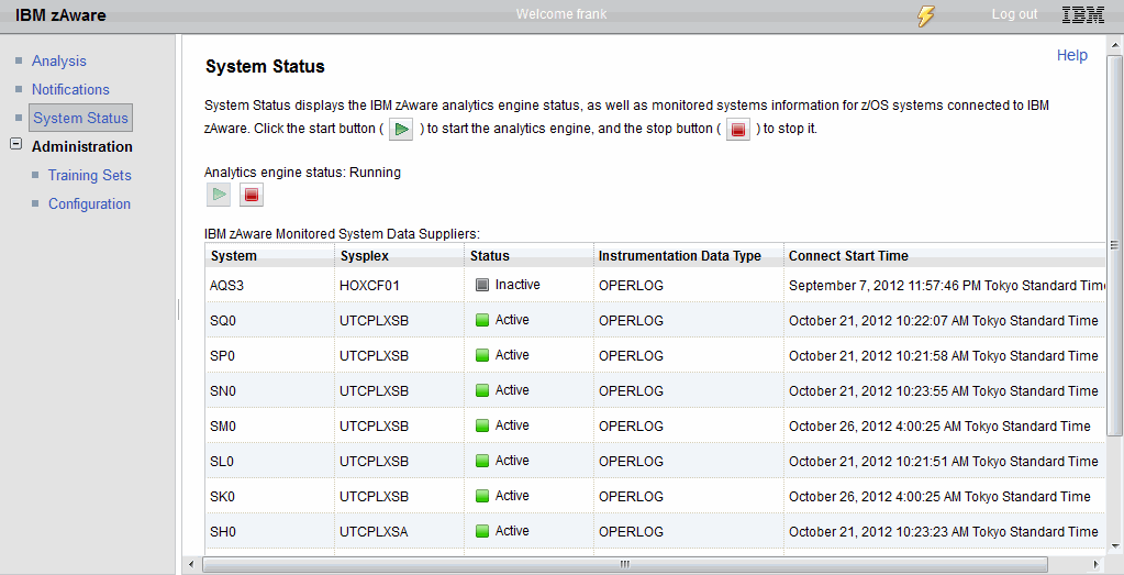
Figure 4-51 System Status on the IBM zAware GUI
3. Perform the bulk load.
The sample bulk load job is provided in SYS1.SAMPLIB(AIZBLK). Customize the sample job to match your data set names and submit the job. While the job is running, messages similar to the following are displayed:
IXG283I OFFLOAD DATASET IXGLOGR.BARTON.ZAI.LSTREAM.A0000024 576
ALLOCATED NEW FOR LOGSTREAM BARTON.ZAI.LSTREAM
CISIZE=4K, SIZE=11059200
IXG284I OFFLOAD DATASET IXGLOGR.BARTON.ZAI.LSTREAM.A0000023 577
DELETED FOR LOGSTREAM BARTON.ZAI.LSTREAM
When the job completes, check the actual output from the BULKLOAD step to ensure that it completed successfully (do not simply rely on looking at the return codes). Messages similar to those shown in Figure 4-52 are displayed.
|
READY
AIZBLKE BARTON.ZAI.CONTROL CREATECNTLS
An old copy of 'BARTON.ZAI.CONTROL' has been deleted.
Control dataset 'BARTON.ZAI.CONTROL' created.
AIZBLKE ended with a return code of 0.
READY
WHEN SYSRC(EQ 0) AIZBLKE BARTON.ZAI.CONTROL ADDSYSLOGDSN KYNEF.OPERLOGS.JULY
Dataset 'KYNEF.OPERLOGS.JULY' added to 'BARTON.ZAI.CONTROL'
AIZBLKE ended with a return code of 0.
READY
WHEN SYSRC(EQ 0) AIZBLKE BARTON.ZAI.CONTROL DISPLAYCNTLS
Line 1 - /* List of SYSLOG files to be imported to zAware */
Line 2 - KYNEF.OPERLOGS.JULY
AIZBLKE ended with a return code of 0.
READY
WHEN SYSRC(EQ 0) AIZBLKE BARTON.ZAI.CONTROL IMPORT DUMMY BARTON.ZAI.LSTREAM BARTON.ZAI.LSMODEL
Reading control dataset 'BARTON.ZAI.CONTROL'.
'KYNEF.OPERLOGS.JULY' is a non-ANSI data set.
Importing 2,500,000 records from 'KYNEF.OPERLOGS.JULY'.
All 2,500,000 records written.
Importing 129,951 records from 'KYNEF.OPERLOGS.JULY'.
All 129,951 records written.
269,662,371 bytes queued to zAware.
AIZBLKE ended with a return code of 0.
|
Figure 4-52 Sample output from BULKLOAD step
To confirm that the bulk load has completed, check the System Logger buffer usage using the following command:
DISPLAY LOGGER,STATUS,ZAI
4. Use the IBM zAware GUI to assign the system to the correct sysplex.
The message data that is send to IBM zAware by the Bulk Data Load Utility contains the system name of each system (because that is contained in every message). However, it does not know the name of the sysplex that the system is a member of.
Therefore, you need to provide that information by assigning the new system to its correct sysplex using the Administration → Configuration → Priming Data tab.
Click each system you want to add to the sysplex in the Priming message data by system box.
|
System connection consideration: Before you can assign a system to a sysplex, at least one system in that sysplex must have connected to IBM zAware at least once.
|
Click the radio button next to the sysplex name for the systems.
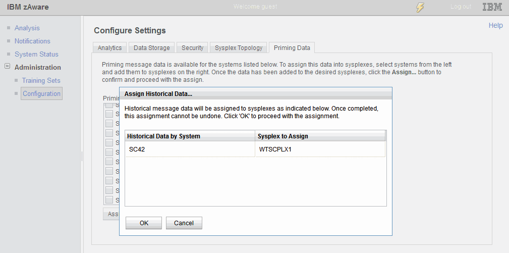
Figure 4-53 Assign systems confirmation window
Confirm that the system to sysplex mapping is correct and then press OK. The window shown in Figure 4-54 will display.
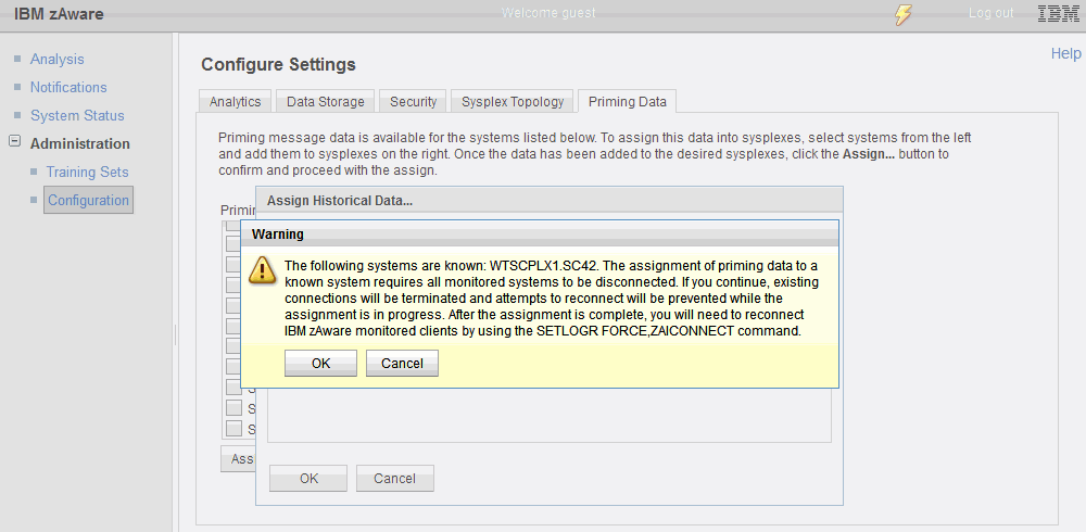
Figure 4-54 Assign systems warning message
5. Ensure that the system successfully reconnected with the IBM zAware server.
When you assign the bulk load data for a system to its sysplex, the analytics engine temporarily disconnected from all connected monitored clients. is recycled. When the assign processing completes, connections from the monitored clients can be restarted.
On the z/OS end, when System Logger sees the connection being terminated from the IBM zAware end, it will automatically attempt to reconnect. It will continue its reconnection attempts for up to 20 minutes.
If it is unable to successfully reconnect for some reason, issue the following commands:
DISPLAY LOGGER,STATUS,ZAI,VERIFY (Confirm the connection is established)
SETLOGR FORCE,ZAICONNECT,LSNAME=SYSPLEX.OPERLOG
6. Train the system.
Having performed the bulk load for the system and assigned it to the correct sysplex using the IBM zAware GUI Assign panel, you are ready to train the system.
Follow these steps:
a. Logon to the IBM zAware application web page at:
Or use:
b. Click the Training Sets option within Administration.
c. Locate the system you want to train and click the radio button to the left of the system name.
|
Training considerations: You can only train one system at a time, and the system to be trained must be connected to IBM zAware.
You can select multiple systems for training, but only one system will be trained at a time. Additional systems selected will be queued.
|
d. Click the Actions button at the top of the list of systems.
e. Click Request Training from the list of actions. You will receive a message about a model being queued for rebuild; click OK.
Figure 4-55 shows the result of requesting training on two systems. The first system has a status of In Progress and the second system shows In Queue. When training completes, the status will change to Completed or Failed. If the status is Failed, refer to 5.5.2, “Creating and updating the system model” on page 168, for information about this topic.
When a training is completed, analysis information about the monitored client will begin to be displayed on the Analysis page.
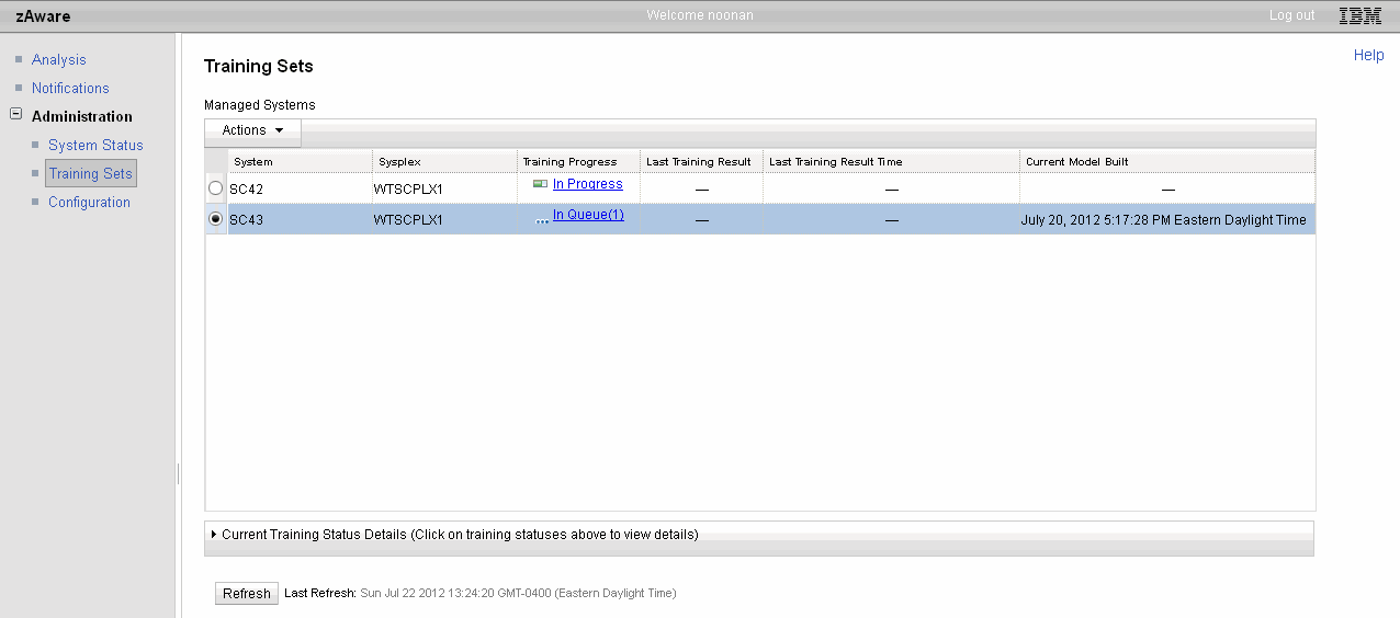
Figure 4-55 Training status
|
Training considerations: The first training starts based on the first date that data is available for (loaded in the database) versus the current date (actually, yesterday). If this difference satisfies the training period (the default is 90 days), then IBM zAware will attempt to train automatically.
If you do not have enough data to satisfy the training period, you may choose to manually train with less data. After the first model is built successfully, “scheduled training” will be started based on the training interval (the default is 30 days), and is only driven for a connected monitored system.
|
1 Note that the bulk data load exec does not support JES3 DLOG format. Therefore, the only way to perform a bulk load for a JES3 system is if you have OPERLOG archive files for that system.
..................Content has been hidden....................
You can't read the all page of ebook, please click here login for view all page.