Everywhere you look in the real world, you see things that are linked together: a dog and its tail, a ribbon and a bow, a train engine and its caboose. And then, of course, there’s that song about the hipbone connected to the thighbone. In Flash, you’ve always been able to draw these objects, but not until CS4 could you link them together so they’d move in your animation as if they were actually connected. Now using the Bone tool, you can link objects, so when you move the hipbone, the thighbone automatically moves in a realistic manner. The animation tool you use is appropriately called a bone; specifically an IK Bone. IK stands for inverse kinematics, which is the type of animation algorithm at work here, but you don’t have to remember that. You can just call them bones, and know that you’re using the same technology that computer game developers use to make onscreen characters move realistically.
In this chapter, you’ll learn about the two different ways you can use Flash’s Bone tool—with symbols and with shapes. When you use bones with symbols, you link one symbol to another. For example, suppose you have a train in your animation. Each car is a separate, carefully drawn symbol. Using bones, you can link the engine to the coal car, the coal car to the boxcar, and so on, all the way down to the caboose. The other way you can use bones is with shapes. In the past, if you wanted to draw a snake, you’d have a hard time getting that snake to squirm and slither properly. You had to painstakingly reposition, distort, or even redraw several versions of the snake to make a good animation. Now you can draw a snake, place bones inside that single shape, and then bend that shape into realistic poses, which makes it easy to reposition or pose your snake for some realistic slithering and sliding.
Note
The IK Bones features discussed in this chapter work only with ActionScript 3.0 documents. When you want to use bones, make sure that you use the command File → New → Flash File (ActionScript 3.0) to create your new documents.
What better way to show how IK Bones link one symbol to another than with a chain made up of separate links? Just to show that all the linked symbols don’t have to be identical, you can throw in a padlock at the end. If you want to get a feeling for the end result, open the file chain_links_finished.fla. If you’re ready to start earning your bones, open the file chain_links_begin.fla. You’ll find both files on the “Missing CD” page at http://missingmanuals.com/cds.
Open the Flash document chain_links_begin.fla.
There are six hollow ellipses on the stage that look like the links in a chain. In the Library, there are two Movie Clip symbols: link and padlock. The links on the stage are different colors. Click a link to select it, and then in the Properties panel under Color Effect, you’ll see that it’s colored using the tint color effect.
Drag the padlock symbol from the Library and position it on the stage so the lock’s shackle overlaps the right-most link in the chain, as shown in Figure 8-1.
Before you start linking symbols together, you need to make sure you have every symbol on the stage. You can’t add new symbols to the IK bones layer after you’ve created a bone with the Bone tool.
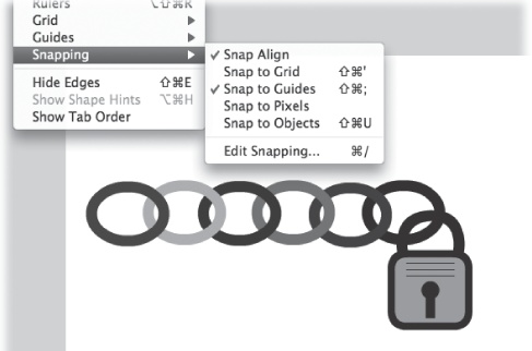
Select View → Snapping → “Snap to Objects” to turn “Snap to Objects” off.
It’s easier to position bones precisely in objects if you turn off the cursor’s snapping action.
Click the Bone tool (or press X, the hot key for the Bone tool).
The Bone tool is in the middle of the Tools palette, and there are two tools under the Bone icon. The one on the top is Bone tool; the one on the bottom is the Bind tool. The cursor for the Bone tool is a bone and a + sign. When the Bone tool is over an object to which you can attach a bone, the solid black bone turns into a hollow bone.
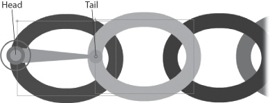
Click the left side of the left-most link, and while holding the button down, drag to the right until you reach the left side of the next link, as shown in Figure 8-2.
You may want to zoom in, so that you can carefully place each bone. You drag to create a bone. The first place you click creates the head of the bone, when you release the mouse button, you create the tail of a bone. The head indicated by the large circle becomes the registration point for the bone, and the symbol to which it’s attached. That means that the bone symbol pivots around the head of the bone. When you create a series of bones, known in Flash-speak as an armature, the first bone is known as the root bone. The head of the root bone takes on special importance, since it’s the registration point for the entire armature or family of symbols.
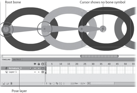
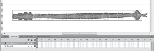
If you glance at the timeline, you notice that adding the first bone creates a new armature layer (also called pose layer) in the timeline (Figure 8-3). Similar to a motion tween layer, the pose layer has special properties.
From the tail of the first bone, drag to create another bone that connects to the next link in the chain.
You can attach bones to either the head or the tail of the first bone. In this case, you attach a second bone to the tail. As you drag, notice that the cursor shows a “no” symbol (circle with a line through it) when you’re over the empty stage or some other object where it’s not possible to link your bone. It turns back to a + when the cursor is over a suitable target.
Figure 8-3. When you create a bone, Flash automatically creates an “armature” or pose layer. The pose layer is similar to a motion tween layer but with a couple of twists to make it work with bones.
When you link to a new symbol, Flash automatically repositions the transformation point to the point where the bones connect. The transformation point is the point around which the symbol rotates.
Repeat this process for the remainder of the chain links until you finally connect the last bone to the padlock’s shackle.
In this animation, all the links in the chain are instances of the same symbol, but often you’ll use bones with lots of different symbols. For example, if you were applying bones to the symbols that make up a human body, there’d be separate symbols for the head, neck torso, parts of the arms and hands, and so on.
In the pose layer, click Frame 30, and then press F5 to create a frame.
The pose layer extends to become 30 frames long. You can make the pose layer any length you wish, and you can add and remove frames from the pose layer as you would any other layer.
With the Selection tool, click Frame 5, and then drag the padlock to a new position (Figure 8-4).
The pose layer is similar to a motion tween layer (Creating a Motion Tween Path). When you reposition the padlock in Frame 5, Flash creates a tween to animate the motion from Frame 1 to Frame 5. The frame where you create a new pose is marked with a small diamond, and it’s called a pose frame.
Figure 8-4. Pose the chain by dragging the lock or by dragging individual links. When you drag a link, the links up to the top rotate around their transformation points; the links down to the lock don’t rotate.
The bones connecting all the links in the chain and the padlock constrain the movement of each symbol, giving the entire family of symbols a realistic sense of motion. Not only that, it’s easier for you, the artist, to position the symbols, because they really are connected to each other.
Click Frame 10 and reposition one of the middle links in the chain.
Bones have a parent-child relationship. When you move one of the middle links, the motion is different, in that the links on the tail end of the chain move as one group. With a little practice, you’ll learn to use the parent-child relationship of the bones to quickly pose linked symbols.
Every five frames or so, continue to pose the chain and padlock.
Experiment to get a feeling for the motion. You can create a new pose by dragging either a bone or the symbol attached to the bone. You can use either the Selection tool or the Bone tool to create a pose. If you want a quick preview, press Enter to see the animation play. You can make it swing back and forth, like a chain attached to a wall or a door, or you can make it move like a snake charmer’s cobra. Try some different techniques and positions.
Press Ctrl+Enter (⌘-Return) to test the animation.
The chain links and the padlock move. The head of the root bone acts as an anchor. The entire armature can pivot around the head, but it remains fixed at that point.
Creating just the right motion is more art than science. Think about how many movement details there are in a running cheetah, or a swinging pendulum, or a slithering snake. Chances are you’ll fiddle with the pose layer after you finish using the Bone tool. For example, you may want to slow down or speed up the action. You may want to hold the armature (that is, all the linked bones and their related symbols) in a certain position for a few beats, and then continue the motion. You may want to smooth the motion or make it more erratic. You can make those changes by changing the relationship of the pose frames in the pose layer. For example, adding or removing frames changes the timing of the animation. Copying and pasting frames can freeze the action for an interval.
For most actions, you need to select specific frames in the pose layer before you cut, copy, paste, and so on. In many respects, you manage the pose layer and its frames the same way you manage other layers. Its behavior is similar to that of motion tween layers. The pose layer is colored green so you can distinguish it from normal layers and tween layers, which are shaded with other colors. There’s also a little figure of a person to the left of the layer name. Each frame with a small diamond is pose frame. These frames are similar to keyframes in a normal standard layer, they mark a point in the timeline where you’ve defined exactly how the animated object is positioned. Flash is responsible for positioning (tweening) the other frames.
Here’s the lowdown on some common operations you can perform in the pose layer.
Speed up or slow down animation. Move the cursor to the end of the pose layer. When the cursor is over the right edge, the cursor changes to show arrowheads pointing left and right. Drag to extend or shorten the pose layer. Flash inserts or removes frames making the playing time longer or shorter. As much as possible, Flash keeps the pose frames in the same position relative to each other. Of course, if you really shrink the layer, all the pose frames get bunched together.
Select frames. When you click the pose layer, you select the entire layer and it changes from green to blue. The playhead moves to the frame that you clicked, but a single click doesn’t actually select the frame. To select a single frame Ctrl-click (⌘-click) a frame. When you select a single frame, it turns blue and the rest of the pose layer returns to its green color. To select a sequence of frames in the pose layer, Ctrl-drag (⌘-drag) over those frames. Once the frames are selected, you can copy, cut, or delete them.
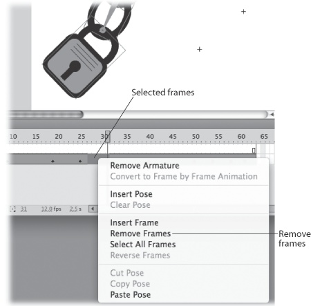
Remove frames. After you’ve selected the frames you want to remove, right-click (or Control-click) the selected frames. A shortcut menu appears, displaying options related to the pose layer, as shown in Figure 8-5. Click Remove Frames to remove all the selected frames. (This action removes the standard frames in the pose layer as well as pose frames.)
Insert a pose. The pose layer has two types of frames. The pose frames, which display a small diamond, are like keyframes for the armature, where you position every part of the armature just the way you want. The other frames are tweened frames, where Flash determines the position of the armature. You can turn a tweened frame into a pose frame in a number of ways. First, move the playhead to the frame you want to change, and then press F6. Flash turns the frame into a pose frame. You can also right-click the frame in the pose layer, and then choose Insert Pose from the shortcut menu. Inserting a pose doesn’t add any frames to the timeline; it simply converts the frame at the playhead to a pose.
Clear a pose. If you want to clear a specific pose frame in your timeline, but leave the rest of it intact, click the frame you want to change. You don’t need to Ctrl-click (or ⌘-click) in this case. The playhead moves to the clicked frame. Right-click (or Control-click), and then choose Clear Pose from the shortcut menu. This action removes the pose, but doesn’t remove the frame. The position of the armature changes because it’s now controlled by the closest pose frames before or after the displayed frame. If you want to clear several pose frames at once, you can Ctrl-drag (⌘-drag) to select several frames, right-click, and then choose Clear Pose to convert the pose frames to standard frames. Clearing a pose doesn’t remove frames from the pose layer.
Copy a pose. If you want your carefully positioned armature to remain in the same position for a few frames, one way to do that is to copy the desired pose, and then paste it back into the pose layer. The frames in between two identical pose frames will all be the same. To copy a pose, Ctrl-click (⌘-click) to select a frame in the pose layer, right-click it, and then choose Copy Pose from the shortcut menu.
Cut a pose. Similar to copying a pose, except that it actually removes the pose from the frame at the playhead. You can then paste it somewhere else (earlier or later) in the pose layer. To cut a pose, Ctrl-click (⌘-click) to select a frame in the pose layer, right-click it, and then choose Cut Pose from the shortcut menu.
Paste a pose. When you copy or cut a pose, the next logical action is to paste that pose into the pose layer on a different frame. Ctrl-click (⌘-click) to select the frame where you want to place the pose. Then, right-click (Control-click) and choose Paste Pose from the shortcut menu.
In the lock and chain example earlier in this chapter (Linking Symbols with Bones), the armature linked symbols together in one long chain. Often, though, you want to create an armature that branches out at different points. The classic example is a human body. For this exercise, start with a new copy of the file robot_begin.fla from the “Missing CD” page at http://missingmanuals.com/cds.
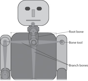
In this example, you’ll operate on a robot with a somewhat human shape. As shown in Figure 8-6, the armature for the robot isn’t quite complete.
Open the file robot_begin.fla. In the “right arm” layer, click the show/hide button (beneath the eye icon).
All the pieces for the right arm are in a separate layer from the pose layer and the armature. You can’t draw directly in a pose layer with an existing armature, but you can add symbols from another layer to an existing armature.
With the Bone tool, click the thick circle in the root bone, and then drag a new branching bone to the right shoulder, as shown in Figure 8-6.
Figure 8-6. The root bone (circled) goes from the upper torso to the neck. Branch bones are already created to the left arm and down to the hips. Here, a new branch is being created to the right shoulder.
When you connect from the root bone to the upper arm (technically called the humerus) the symbol is automatically moved from the “right arm” layer to the pose layer, and the bone is connected.
Continue to create bones for the robot’s right arm and hand.
As each bone is added, the connected symbol is moved from the right arm layer into the pose layer.
You can add bones that branch from the head or tail of any bone, and, as you see in this example, you can create multiple branches from the same joint. So, if you want to create a spider, for example, you can create eight legs that all connect to the same joint.
Bodies, even robot bodies, have their limits. You don’t want your robot flapping around like a rag doll. In terms of IK Bones, that means you don’t want every bone in the robot armature to have full movement to rotate 360 degrees. Constraining rotation is one of the ways you can create realistic movement when you’re using bones. Once you put constraints on rotation, it’s easier for you to set up pose frames, too. Also, by turning off Joint: Rotation, you can prevent bones from pivoting around specific joints. If you want to provide a certain degree of motion around a point, you leave the Joint: Rotation turned on, but constrain the motion, by providing a minimum and maximum number of degrees for rotation.
Tip
When you work with more complex armatures with lots of branching bones, it’s sometimes hard to control all the flopping parts. When you’re just getting started it’s helpful to save (File → Save As) multiple copies of your file with different names, like robot_arms_down.fla or robot_running.fla. Save a few versions where you’re happy with the poses. Then if things get out of hand as you’re working on your file, you have a saved file as a backup.
In the next few steps, you see how to prevent rotation and how to constrain rotation.
In the robot_begin.fla from the previous section, click the bone you created in step 2 on Creating Branching Armatures.
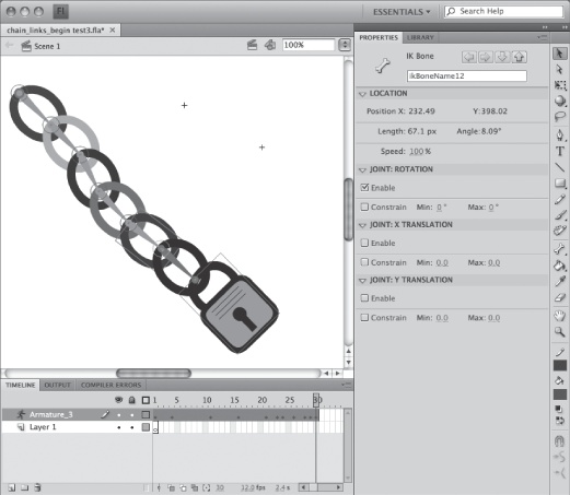
When you select the bone that connects the root bone to the top of the right arm, the Properties panel shows settings specific to that bone. There are four subpanels: Location, Joint: Rotation, Joint: X Translation, and Joint: Y Translation.
In Properties → Joint: Rotation, click to turn off the Enable checkbox.
Once you turn off the Enable checkbox for Joint: Rotation, the armature won’t pivot around that joint. You want the robot’s arms to pivot around a joint near the shoulder, not in the center of the torso.
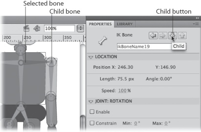
With the bone still selected, click the Child button at the top of the Properties panel (shown in Figure 8-7), to select the bone that connects to the right forearm.
The humerus bone is selected, and the Properties panel shows the related settings.
Drag the selected bone to examine its movement.
The horizontal bone from the torso to the top of the arm remains locked in place, in effect creating a shoulder. The humerus pivots around the joint at the top of the bone. It can pivot a full 360 degrees.
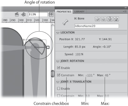
Under Properties → Joint: Rotation, click the Constrain button.
With a check in the Constrain checkbox, the Min and Max settings come to life.
Enter a value of –132 in the Min box and a value of 45 in the Max box.
Min and Max settings are displayed as degrees. You can click and type in a value or you can scrub in a value. Scrubbing is a good option, because Flash shows the joint’s angle as you scrub, as shown in Figure 8-8. With the constraints, the robot arm has a more appropriate range of movement. (Well, appropriate for a robot, not what you’d want in a major league pitcher.)
If you want to create a well-behaved robot, you can repeat these steps to turn off or constrain the rotation in the other joints. Once you’ve done that, you can make your robot dance a jig by creating different poses in the pose layer.
No matter how talented or lucky you are, it’s unlikely you’re going to get your IK Bones animations exactly right the first time you set them up. You can, and probably will, edit the pose layer (as shown on Changing the Pose Layer), and edit the armature (as described in this section).
Here’s a good example of a problem and solution continuing from the exercise begun on Linking Symbols with Bones. If you drag the padlock down as far as it can reach, it ends up beyond the bottom of the stage. The next few steps show how to move the entire chain and padlock up higher in the animation.
Here are the steps to move the entire armature to a new location:
Open the Flash document chain_links_begin.fla.
If you haven’t done the steps on Linking Symbols with Bones, do so now. Then continue here with step 2.
Click to select the first frame in the pose layer.
The playhead moves to the first frame in the layer.
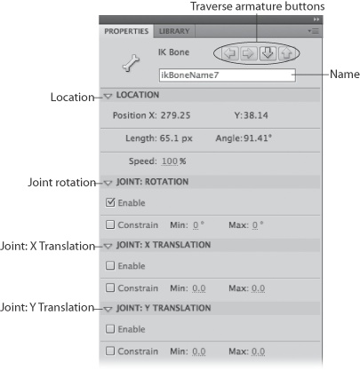
The root bone is the first bone that you created, and in this case, you need to actually select the bone; just selecting the symbol attached to the bone won’t do the trick. A selected bone turns green; unselected bones are colored purple. When you move the root bone to a new location, the other bones (sometimes referred to as children or child bones) move with the root.
When you select any bone, the Properties panel displays settings related to the bone. The subpanels include: Location, Joint: Rotation, Joint: X Translation, and Joint: Y Translation (Figure 8-9).
Figure 8-9. Select a bone, and you see these settings in the Properties panel. Click the buttons at the top to change the selection to a different bone. Use the Joint: Rotation setting to let a bone pivot—or restrict the way a bone pivots. Turn on the Joint: Translation settings if you want to move a bone on the stage.
In Properties → Joint: Rotation, click to turn off the Enable checkbox.
When you first create a bone, Joint: Rotation is turned on and Joint: X Translation and Joint: Y Translation are turned off. These initial settings give you the kind of motion that you want most of the time.
Turning off Joint: Rotation on this bone prevents the entire armature from spinning around when all you want to do is move it.
In Properties → Joint: X Translation, turn on the Enable checkbox. Do the same in Properties → Joint: Y Translation.
With Joint: X and Joint Y Translation turned on, you can move the root bone and the entire armature along the X and Y axes.
Drag the root bone up to the top center of the stage.
The root bone and the armature move slowly as you drag them to a new location. There may be some rotation around the joints of some of the child bones as you move the armature. You can prevent this movement by turning off Joint: Rotation. Remove the check mark from Properties → Joint: Rotation → Enable.
Turn Properties → Joint: Rotation back on. Turn both Properties → Joint: X Translation and Properties → Joint: Y Translation back off.
Now that you’ve moved the armature, you want to reset the properties of the root bone to their previous settings.
Drag the padlock and some of the links on the chain.
Notice that the armature’s movement and action hasn’t changed; just the location.
In these steps, you changed the location of the chain in Frame 1. If you move the playhead along the timeline, you see that this move didn’t change the chain’s position in the other pose frames. This setup probably isn’t what you want for this particular animation, but it shows a point. One way to create movement about the stage when you’re working with an armature is to move the root bone between poses. Another way to animate movement is to wrap your armature inside of a movie clip or graphic symbol, and then use a motion tween to create movement around the stage.
You don’t always want your symbols to move in lockstep. There are times when you want some of the symbols to rotate on their own or even move away from the rest of the armature. For example, suppose you have a clown cartoon character who keeps losing his hat. The hat bounces around his head at different angles and perhaps it even flies off, only to snap back into place.
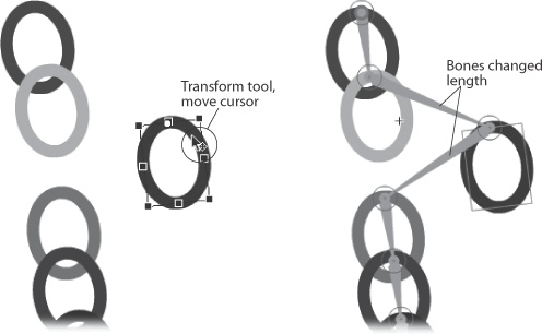
When you connect symbols to each other using bones, you can reposition the symbols independently using the usual transform tools. For example, you can “break” the chain in the previous example, as shown in Figure 8-10. Select the Transform tool, and then rotate one of the links in the middle of the chain. The link pivots around its transformation point. Using the Transform tool to rotate an instance of a symbol doesn’t change the length of the bones in the armature.
If you want to move the symbol, including its transformation point, you have to change the length of the connected bones. That’s also a job for the Transform tool. Select the Transform tool, and then move the cursor over the symbol you want to move. Drag the symbol to a new position. As an alternative, you can use the Selection tool to move a symbol; just press Alt (Option) as you drag.
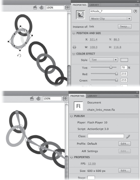
Figure 8-10. Top: To reposition a symbol relative to the bone armature, use the Transform tool. Bottom: The link has pivoted around its transformation point, but still moves with the rest of the armature.
Flash doesn’t display the armature when you use the Transform tool. When you’re done, select the symbol, and you’ll see how the length of the bones have changed to accommodate the move, as shown in Figure 8-11.
Deleting bones from an armature is a pretty straightforward procedure. Just select the bone, and then press Delete. The bone disappears along with any child bones connected to it. The symbols that were connected by the bone remain in the pose layer, but they’re no longer connected to the armature, so they aren’t animated with the other symbols.
There are two different ways to use bones. You can use IK Bones to link symbols together, creating a chain of objects (as described on Linking Symbols with Bones) or you can add bones to the inside of a shape, making that shape bendable and flexible. It’s kind of like dressing up a group of bones inside of a costume. Though both these methods rely on an armature made up of bones, the techniques you use to make them work are quite different.
You can add bones to a single shape or you can add bones to more than one shape. The word “group” isn’t used here, since you can’t combine the shapes using the Group commands. The way you add bones to more than one shape is to select all the shapes that you’re going to include before you add the first bone. Flash then automatically places those selected shapes in the pose layer.
In this exercise, you’ll animate a snake by placing several bones inside of it. Unlike a robot, snakes don’t have limbs, but you can still give them plenty of different bones. Download snake_begin.fla from the “Missing CD” page at http://missingmanuals.com/cds.
Open snake_begin.fla.
The lovely rattlesnake is made up of several shapes: a body, a tongue, and two eyes.
Zoom in on the front section.
To place bones precisely inside of a shape, it helps to zoom in for a close view. Then, if you need to get a view of a different part of the shape, you can use the Hand tool to reposition the object on the stage.
Select the tongue, the body, and the eyes.
You can add bones to more than one shape, but you can’t group those shapes with the Modify → Group command when you add the bone. Instead, you have to select all the shapes you want to include in the IK shape object.
With the Bone tool, drag to create a bone from the snake’s head to the tongue.
When you create the first bone, Flash converts all the selected shapes and the bone into an IK shape object and places the object in a pose layer.
Create a bone from the root bone down the body of the snake.
You can attach bones to both the head and tail of the root bone. You can also create branches in shapes. (Creating Branching Armatures describes creating branching armatures when linking symbols.)
Create several more bones inside the body of the snake down to the tail.
Use a total of about eight or nine bones for the snake’s armature (Figure 8-12). If you use too many bones, it’s more work for you when you try to pose the snake. Too few bones, and you won’t be able to create the desired snaky slithering.
In the pose layer, click Frame 50, and then press F5.
The green pose layer shows 50 frames for you to create some snaky movement.
Create several poses to animate the snake so that it moves across the stage from left to right.
Here are some suggestions: In Frame 1, start with the snake offstage to the left. In Frame 5, pose the snake with just the head coming on to the stage. In Frames 10, 20, 30, and 40, pose the snake in different S-shaped curves to simulate snake propulsion across the stage. In Frame 45, show just the snake’s rattle with the rest of the snake body already offstage. In Frame 50, move the snake entirely off stage to the right.
Test the animation.
If you’re not pleased with the movement at any stage, try to reposition the adjacent poses or create more intermediate poses.
You use the pose layer to animate the position and location of the armature. In many ways, the pose layer seems like a motion tween; however, you can’t use the pose layer to tween properties like color, transparency, or dimensions. If you want to change these properties, you need to select the pose layer, and then wrap it in either a movie clip or a graphic symbol. There are more details in the box on Changing the Pose Layer.
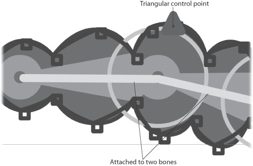
When you place bones inside of shapes, Flash automatically creates control points around the contour of the shape, as shown in Figure 8-13. The control points establish the perimeter of the shape as you create different poses. Some shapes, especially more complex and branched shapes, can get contorted in unexpected ways. You can solve the problem by repositioning the control points. With the Subselection tool, click the boundary of the shape. The control points and the edge of the shape appear highlighted. Then, just drag the control points to adjust the shape. Control points at a curve show Bezier-style curve control handles that you can use to modify the curve.
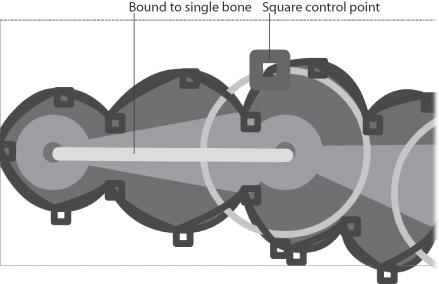
Figure 8-13. Flash automatically creates control points around the edge of shapes when you add bones. You can change the contour of a shape by dragging the control points.
When you add bones to a shape, Flash binds the control points on the perimeter of the shape to the nearest bone. In some cases, a control point may be bound to more than one bone as shown in Figure 8-14. If the control points aren’t configured the way you’d like, you can edit them using the following techniques:
View control points bound to a bone. Choose the Bind tool in the Tools panel, and then click a bone in the armature. The selected bone shows a red highlight. The control points bound the selected bone are highlighted in yellow. The other control points in the armature are colored blue.
View bones bound to a control point. Choose the Bind tool in the Tools panel, and Flash displays the bones and control points in the armature. Square control points are bound to a single bone. Triangular control points are bound to more than one bone. Click a control point, and it shows a red highlight. Bones bound to the control point are highlighted in yellow.
Bind a control point to a bone. Choose the Bind tool in the Tools panel, and then click a bone. The control points bound to the bone appear highlighted in yellow. With the Bind tool, Shift-click a control point that doesn’t show a yellow highlight, and Flash binds it to the selected bone.
Remove (unbind) control points from a bone. Use the Bind tool to select a bone. Ctrl-click (Option-click) a control point that’s highlighted in yellow. The control point changes from yellow to blue, indicating it’s no longer bound to the selected bone.
Bind a bone to a control point. Select a control point with the Bind tool, and then drag to the bone you want to bind to. As an alternative, Ctrl-clicking (Option-clicking) acts as a toggle, binding and unbinding control points to adjacent bones.
Remove (unbind) a bone from a control point. Select a control point with the Bind tool, and then drag away from the shape to unbind the control point. As an alternative, Ctrl-clicking (Option-clicking) acts as a toggle, binding and unbinding control points to adjacent bones.
Though it’s not covered in this book, you can use ActionScript 3.0 to animate IK Bones armatures. The IK armature has to be connected to either shapes or movie clip symbols. You can’t use ActionScript to animate graphic or button symbols. To prepare an armature for use with ActionScript, create a pose layer with only a single pose. If there’s more than one pose in the layer, you can’t use it with ActionScript.
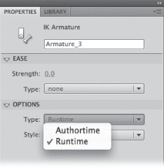
Select a frame in the pose layer.
The settings for the pose layer appear in the Properties panel (Figure 8-15).
In Properties under Options → Type, choose Runtime from the drop-down menu.
When you first create an armature, Option → Type is set to Authortime, meaning you create the animation in the timeline as you design the animation. Once you change it to Runtime, you can use ActionScript code to control the movement of the armature and its elements.
Change the instance name for the armature to amtrChain.
You can change the name of the armature to match your ActionScript naming conventions. Initially, Flash gives the armature instance the same name that’s used to name the pose layer. You can change the name in either the layer in the timeline or in the Properties panel.