
4
Flexible Sodium Ion Batteries: From Materials to Devices
Shengyang Dong Ping Nie and Xiaogang Zhang
Nanjing University of Aeronautics and Astronautics, College of Material Science and Engineering, 29 Jiangjun Avenue, Nanjing, 211106, China
4.1 Introduction to Flexible Sodium Ion Batteries (SIBs)
Recently, with the increasing development of wearable and flexible electronic devices, including conformable skin sensors, implantable medical devices, and wearable sensors, technologies involving flexible energy storage have attracted increasing attention due to the potential enormous market [1, 2]. These flexible and wearable applications usually integrate with the requirements of the human body to provide smart functions. Moreover, the wearable electronic devices can also remarkably boost their development in the Internet of Things fields such that people, devices, and data are connected and integrated to enrich our daily life [3]. Toward this, the power supply sources require light weight, flexible construction, and conformal design.
It is well known that lithium ion batteries (LIBs) have achieved great success in our daily life and have dominated the market in applications from mobile electronics to electric vehicles (EVs), hybrid electric vehicles (HEVs), and other electric public utilities, because LIBs have a high operating voltage and long cycling life as well as a large energy density, and are less likely to have undesirable influence caused by a memory effect [4, 5]. However, the rapid consumption of lithium resources driven by the tremendous demand in EVs and large‐scale energy storage may eventually render lithium resources unaffordable since lithium is rare and its distribution is geographically restricted. Thus, pursuing sustainable flexible power technology for flexible and wearable electronic applications becomes increasingly important. In contrast to lithium, sodium is the sixth most abundant element in the Earth's crust (≈2.6%), and virtually unlimited sodium resources are available in sea water [6]. Additionally, sodium has physical and chemical properties similar to those of lithium. Therefore, sodium ion batteries (SIBs) have attracted great attention as a promising alternative to LIBs [7, 8].
Similarly to LIBs, SIBs, including the flexible SIBs, also have a “rocking‐chair” working mechanism. In a typical flexible SIB configuration: flexible anode, flexible cathode, and electrolyte are the three major components, as shown in Figure 4.1. The SIBs function by converting chemical energy into electrical energy via Faradaic reactions, accompanied by insertion/extraction of sodium ions into/from the crystalline framework of electro‐active materials [9, 10]. On charging, sodium ions de‐intercalate from the cathodes, pass across the electrolyte, and intercalate into the anodes. The above process is reversed during the discharge process. Sodium ions diffuse through bulk diffusion while electrons move in the opposite direction and pass around the external circuit.

Figure 4.1 Schematic of flexible sodium ion batteries.
In general, the specific capacity, cycle life, rate capability, and mechanical flexibility are the most important performance indicators for flexible SIBs, which are strongly dependent on the properties of the electro‐active materials and the design of flexible electrodes [11]. As far as the flexible electrodes are concerned, the morphology, crystal structure, and composition can influence the rate properties and transfer processes of ions/electrons and can be manipulated to alter the overall electrochemical properties of the flexible device [12]. Therefore, the key challenges in achieving flexible SIBs lie in the selection and design of bendable electrodes with good mechanical flexibility and the fabrication of flexible electro‐active materials with a high capacity and excellent conductivity. The ductile and flectional electrodes combine with the nanostructured electro‐active materials rendering them as promising candidates for flexible SIBs [13]. Additionally, the electrochemical reactions of batteries are commonly determined by ion and electron transfer through the bulk of the electrodes. By employing nanostructured materials, the fast charge/discharge properties can be highly enhanced by shortening the diffusion pathway of ion and electron [14].
4.2 The Key Scientific Issues of Flexible SIBs
In order to construct a reliable flexible device, flexible SIBs must possess highly reversible electrochemical behavior and mechanical properties, before, during, and after the process of deformation [15]. SIBs usually consist of several main components including cathode, anode, separator, current collector, electrolyte, and package materials, all of which must be capable of being bent, stretched, even compressed so as to be compatible for flexible SIBs. Therefore, the crucial aspects toward the design of flexible SIBs include the development of advanced electro‐active materials, deformable substrates, and mechanically durable electrodes and circuits. Besides these, novel processing technologies and system integration are also very important [3].
4.2.1 Design of Advanced Active‐Materials
Generally, developing novel elastic materials and structural designs are main routes to achieving flexible devices. However, developing intrinsically flexible materials is extremely difficult, because it needs to meet many different technical demands [15]. Compared to conventional inorganic materials, organic materials have better stretchability, and possibly lower cost, which enable devices to have some flexibility [16]. Although many works have focused on the design of organic material‐based flexible devices, their electrochemical performance is still incomparable to that of inorganic material‐based devices. Inorganic materials, such as metal oxides, hard carbon, and activated carbon, usually suffer from extremely low elastic limit (usually <0.1%) [15]. They are intrinsically brittle, and are not capable of accommodating a harsh mechanical deformation. Thus, conventional inorganic materials are the major challenge to developing flexible SIBs.
4.2.2 Design of Flexible Substrates and Electrodes
The conventional electrode is usually prepared by using the slurry‐coating technology. The electro‐active materials, such as metal oxides, hard carbon, and other inorganic materials are made into slurry with conductive additives and polymer binders, and further coated on Al or Cu foil current collectors that are rigid. Besides, these electro‐active materials are intrinsically brittle with an extremely low elastic limit [17]. As a result, the electro‐active materials may easily peel off from the Al or Cu foils during repeated mechanical deformation. Currently, flexible electrodes are typically prepared by incorporating electro‐active materials onto flexible or/and conductive substrates [18–20]. For example, the unique physical, chemistry, mechanical, and electrical properties of graphene make it a promising candidate for incorporation in flexible substrates to produce flexible SIBs [21, 22].
Currently, flexible devices can be classified into three categories according to their loading type – bendable, stretchable, and compressible devices [15], as shown in Figure 4.2. Among them, bendable SIBs are the most investigated. The key issue for bendable SIBs is to develop reliable flexible electrodes. Suo investigated the strain in a film coated on a substrate in detail. The strain in the top surface (![]() top) can be obtained by the equation 23, 24]:
top) can be obtained by the equation 23, 24]:
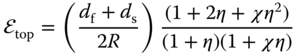


Figure 4.2 Classification of flexible electrodes.
Source: Wen et al. 2016 [15]. Copyright 2016. Reproduced with permission from John Wiley and Sons.
where df and ds, Yf and Ys are the thickness and Young's moduli of the film (electro‐active materials) and substrate, respectively, and R is the bending radius. Specially, when the flexible film and substrate have the same Young's modulus, the ![]() top can be simplified as follows:
top can be simplified as follows:

From the theoretical model, Equations 4.1 and 4.4, we can summarize that depositing nanomaterials with a small thickness onto flexible substrates will be a feasible strategy to developing bendable SIBs.
The stretchable device is another common flexible configuration [25]. However, developing stretchable SIBs is more difficult than developing bendable devices. Designing intrinsically stretchable materials for flexible SIBs is extremely challenging. Another feasible strategy to fabricate stretchable SIBs is using stretchable electrode structures. Three novel structures have been developed and demonstrated in flexible LIBs and supercapacitors: wavy layout, coiled fiber structure, and island‐bridge design [26–28]. Although the stretchability can be obtained by wavy layout and helically coiled design, such structures can only be unidirectionally stretched. The island‐bridge structure circumvents this limitation, but the assembly processes are complicated and the stability obtained is unsatisfactory. In fact, coiled fiber, wavy layout, and island‐bridge structures possess a little compressibility to some extent. However, so far, there has been no relevant works on stretchable SIBs. Cui and coworkers [29] reported a novel method to design stretchable electrodes, by using sugar as a template to generate the highly elastic polydimethylsiloane (PDMS) scaffolds with 3D porous sponge‐like structure. They used the Li4Ti5O12 anode and LiFePO4 cathode and demonstrated the practicability of the stretchable PDMS sponges in LIBs. Actually, fabrication of stretchable electrodes is a versatile strategy [29]. Zhang and coworkers developed a simple strategy to prepare nitrogen‐doped carbon foam (NCF) with compressible 3D electrode architectures by direct carbonization of commercially available melamine foam [30]. They used it as a compressible substrate for supercapacitor applications.
4.2.3 Developing Novel Processing Technologies
Conventional energy storage devices usually have simple shapes, such as coins, cylinders, prism, and pouch types [31, 32]. Stress accumulation caused by the geometrical shape during deformation is another challenge for achieving flexible SIBs. To avoid internal stress between components, the processing technology of conventional energy storage devices should be changed [15]. Therefore, novel processing technologies should be developed to allow flexible SIB operation under repeated mechanical deformation. In previous reports, PDMS is the most widely used flexible polymer for fabricating elastic electrodes and packaging devices due to its unique properties, such as wonderful flexibility, stretchability, and chemical stability [29, 33]. In very recent years, printing technologies, especially 3D printing technology, are drawing much attention owing to their large‐scale and high‐throughput production capabilities [34, 35]. That may be a promising choice to developing flexible SIBs in the near future.
4.3 Design of Advanced Materials for Flexible SIBs
4.3.1 Inorganic Anode Materials for Flexible SIBs
For inorganic anode materials, we herein mainly focus on the recent processes involving carbon materials, alloy anodes, metal oxides/sulfides based on conversion reaction and intercalation‐based titanium‐based compounds as flexible electrodes for flexible SIB applications.
Unlike LIBs, graphite has poor electrochemical performance for sodium storage, which might be related to the larger radius of Na+ and also because of thermodynamic issues [36, 37]. Fortunately, disordered carbon, such as hard carbon, soft carbon, and graphene, is particularly attractive due to its disordered structure and larger interlayer distance that could accommodate sodium. Yu and coworkers reported flexible and lightweight porous carbon nanofibers (P‐CNFs) with 3D interconnected structures using simple electro‐spun technology and subsequent pyrolysis process [38]. The P‐CNFs can be directly used as anodes for SIBs, and exhibit a high reversible capacity of 266 mAh g−1 after 100 cycles at a current of 50 mA g−1. Singh and coworker first investigated the electrochemical behavior of reduced graphene oxide (rGO) paper electrode on lithium/sodium storage under different annealing temperatures [39]. They found that the lithium storage capacity increased with increasing thermal treatment temperature in Ar gas from 300 to 900 °C. However, the sodium storage capacity was highest at 500 °C [39], which is due to the decreased interlayer spacing and increasing order of rGO paper during increasing temperatures. Further, they found that both the fracture strength and corresponding strain to failure decreased for rGO paper prepared at increasing treatment temperatures [39]. In order to improve the sodium storage performance of graphene, Shao and coworkers prepared sulfur‐doped flexible graphene films (SFGs) by using thiourea as the reducing agent and sulfurizing agent [40]. The SFGs showed a high reversible capacity of 377 mAh g−1 at 100 mA g−1, which might be related to S doping as it induces larger interspacing layers and creates additional redox sites for reaction with sodium [40].
2D layered transition metal dichalcogenides are promising anodes for energy storage applications [41]. In particular, molybdenum disulfide (MoS2)has received extraordinary attention in recent years as a new anode for SIBs due to its moderate potential, high specific capacity and highly flexible layered structure 42. The electrochemical reaction of MoS2 is based on intercalation and conversion, where Na+ firstly intercalates into the S–S layered space to form NaxMoS2, then the NaxMoS2 converts into the Mo and Na2S phase. David et al. [43] reported a self‐standing flexible electrode composed of acid‐exfoliated few‐layer MoS2 and rGO flakes for SIBs, which is synthesized through vacuum filtration of homogeneous dispersions of acid‐treated MoS2 flakes and GO aqueous solution followed by thermal reduction (Figure 4.3a–e). Furthermore, mechanical tests involving static uniaxial tension reveal good mechanical strength of about 2–3 MPa and high failure strain (approximately 2%) of this rGO/MoS2 composite paper (Figure 4.3f,g). When evaluated as an electrode for SIB, the film shows highly reversible capacity with a stable charge capacity of approximately 230 mAh g−143. For a cost‐effective large‐scale production method for MoS2 exfoliation/dispersion, Hu and coworkers [44] reported an efficient method for MoS2 exfoliation by using a green dispersant, 2,2,6,6‐tetramethylpiperidine‐1‐oxyl (TEMPO)‐oxidized nanofibrillated cellulose in an aqueous solution. Multifunctional MoS2 films were fabricated by filtering with carbon nanotubes (CNTs) and were employed as flexible electrodes for Li/SIBs [44]. Gogotsi, Wang, and coworkers designed a freestanding anode material consisting of molybdenum disulfide nanosheets aligned vertically on carbon paper derived from commercial paper towels [45]. The MoS2 nanosheets were firstly deposited on the flexible substrate, a carbon paper, under hydrothermal process at 180 °C for 24 h, then calcined at 800 °C in Ar atmosphere. The unique structure favors fast electron transfer and electrolyte diffusion, enabling high initial Coulombic efficiency (79.5%), reversible capacity, good cycling performance, and excellent rate capability, delivering a capacity of 205 mAh g−1 at 1000 mA g−1. The reversible phase transition from 2H‐MoS2 to 1T‐MoS2 is observed by using in situ Raman spectroscopy during the electrochemical cycling [45]. Self‐standing electrode of MoS2 nanosheets assembled on graphene foam, which were grown on nickel foam by chemical vapor deposition (CVD) method was achieved by a single microwave‐assisted hydrothermal method. With a high conductive network as well as the interconnected channel properties of the 3D graphene foam, which enable fast electron transport, efficient penetration of electrolyte and short sodium ion diffusion paths, the resulting composites exhibit superior rate performance and high specific capacity of 290 mA h g−1 after 50 cycles at a rate of 0.1 A g−1 in SIBs [46]. As a close analogue to MoS2, MoSe2 has smaller band gap and larger layer space, thus showing better electric conductivity and Coulombic efficiency for SIB application. Zhang et al. reported MoSe2 nanosheets grown on carbon cloth by a solvothermal method as the flexible electrode for SIBs for the first time [47]. When used as a self‐supporting anode directly, the composite delivers high capacity of 452.6 mA h g−1 at 0.2 A g−1, superior rate ability at 5 A g−1, and keeps 85.5% capacity retention after 100 cycles [47].
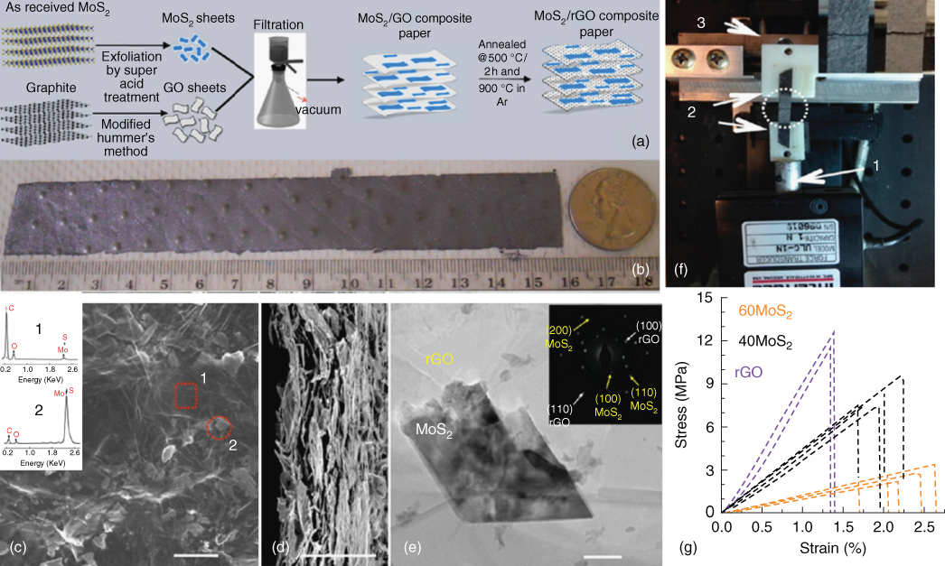
Figure 4.3 (a) Schematic representation showing synthesis of rGO/MoS2 composite paper. (b) Digital picture showing large area composite paper prepared through vacuum filtration. (c) SEM top‐view image of 60MoS2 paper; inset shows the EDX spectra of spots in the SEM image indicating the material to be rGO (square) and MoS2 (circle). The scale is 10 μm. (d) Corresponding SEM cross‐sectional images show the morphology of the paper. Average thickness of this paper was observed to be ∼20 μm. (e) TEM image and SAED pattern of 60 MoS2. (f) Tensile test setup (1, load cell, fixed; 2, clamps, top clamp not shown; 3, computer‐controlled movable translation stage) with sample after fracture from loading (inset shows zoomed‐in view of two such specimens). (g) Engineering stress strain plot for rGO, 40MoS2, and 60MoS2 free‐standing papers.
Source: David et al. 2014 [43]. Copyright 2014. Reproduced with permission from American Chemical Society.
Layered molybdenum trioxide (MoO3) has been studied as an attractive electrode in SIBs due to its high specific capacity, low cost, and resource abundance [48]. However, poor cycling stability has limited its application originating from its low electronic/ionic conductivity and irreversible phase transition. Yao and coworkers investigated partially reduced MoO3−x grown on flexible carbon cloth substrate, where the oxygen vacancy significantly improved the cycling stability and the carbon cloth increased the electronic conductivity of MoO3 material, as shown in Figure 4.4a. The capacity retention is 92% after 2000 cycles at 1 A g−149. Compared to a conventional electrode, the above flexible electrode exhibits lighter weight, favorable mechanical strength, and higher electric conductivity without carbon additive, binder, and metal current collector, demonstrating promising perspective and great potential for high energy and power SIB application (Figure 4.4b,c). Similarly, flexible carbon‐coated FeS on carbon cloth substrate was prepared by a facial hydrothermal methodcombined with a carbonization treatment [50]. When used as free‐standing electrode for sodium storage, it could deliver a reversible capacity of 365 mAh g−1 after 100 cycles at 0.15 C [50].
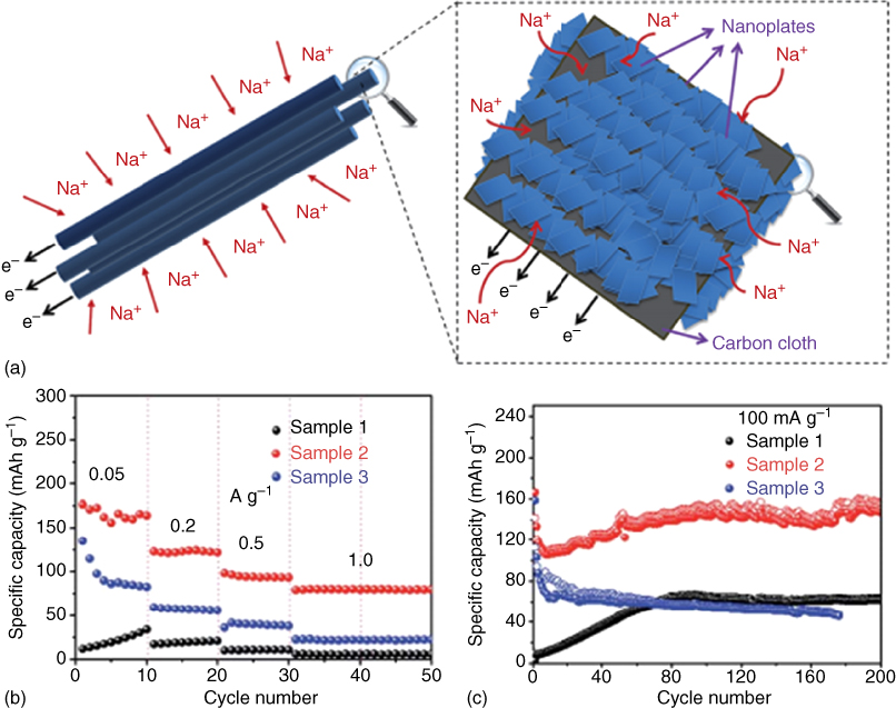
Figure 4.4 (a) Schematic diagram of partially reduced MoO3−x deposited on flexible carbon cloth to enable facile ion diffusion and electron conduction. (b, c) The rate and cycling performance.
Source: Li et al. 2016 [49]. Copyright 2016. Reproduced with permission from Royal Society of Chemistry.
Tin and Tin‐based composites attracted remarkable attention due to their high specific capacity, low cost, and environmental friendliness [51]. However, this kind material usually suffers from deteriorating capacity and cycling stabilities owing to large volume expansion, leading to pulverization of active materials, loss of electrical contact with current collector, and unstable solid electrolyte interphase (SEI) layer [52]. Wang and coworkers [53] reported SnS2@graphene nanosheet arrays grown on carbon cloth substrate as binder‐free anodes for SIBs. The composite is achieved by using a facile two‐step solvothermal route. The integrated structure facilitates efficient electron transfer and fast kinetics, and improved rate and cycling capability was observed for this composite [53]. Very recently, tin nanodots (1–2 nm) encapsulated in porous nitrogen‐doped carbon nanofibers were synthesized through feasible electro‐spinning techniques and thermal treatment processes using polyacrylonitrile, poly(methyl methacrylate), and SnCl2 as precursors, as shown in Figure 4.554. The size and content of Sn particles can be controlled by changing their synthesis condition. The as‐obtained nanofibers with flexible membrane could be directly used as binder‐ and current collector‐free anode for SIBs. As expected, the hybrid film exhibits outstanding rate capability and ultralong cycling performance, and a high specific capacity of 450 mAh g−1 can be delivered at a current density of 10 A g−1. When cycling at 2 A g−1 for 1300 cycles, only 10% capacity loss is observed at such a high rate, which is the highest performance reported for tin electrode in SIBs. They further evaluate its practicability in a sodium ion full cell. When coupled with NaVPO4F/C cathode, the full cell delivers an initial capacity of 540 mAh g−1 with a capacity retention of 85.2% over 100 cycles [54]. Among the reported alloy‐based materials, Sb seems to the most promising anode candidates for SIBs due to its large capacity of 660 mAh g−1 and high electrical conductivity. However, the large volume change during cycling is difficult for the application of Sb‐based materials in SIBs. Wang and coworkers also fabricated antimony/carbon fibers electrode by a simple electro‐spinning method, where ∼30 nm Sb nanoparticles were well dispersed inside the carbon fibers [55]. The binder‐free film exhibits high specific capacity and excellent cycling stability with 92% capacity retention after 100 cycles and 75% over 300 cycles [55].

Figure 4.5 (a) Schematic illustration of the preparation process for Sn NDs@PNC nanofibers. (b) Digital photos of the as‐spun PAN/PMMA/SnCl2 fiber membrane and the calcinated self‐supported Sn NDs@PNC electrode for Na ion batteries. (c) SEM, (d) EDS mapping. (e) Rate capability and cycling performance of Sn NDs@PNC, lower Sn content (L‐Sn@PNC), and higher Sn content (H‐Sn@PNC) electrodes, inset: SEM, TEM, and HRTEM images of Sn NDs@PNC after 300 cycles.
Source: Liu et al. 2015 [54]. Copyright 2015. Reproduced with permission from John Wiley and Sons.
Phosphorus appears to be the most attractive anode candidate for SIBs because of its ultrahigh theoretical capacity of 2596 mAh g−1, attractive potential plateau, and low cost [56]. The main disadvantage is its low conductivity and rapid capacity degradation caused by large volume expansion (>490%) during cycling. Zhang et al. synthesized amorphous P@N‐doped graphene film via the well‐known “phase‐transformation” approach with superior capacity retention of 85% over 350 cycles and rate capability; a high specific capacity of 809 mAh g−1 can be obtained at 1.5 A g−1, as shown in Figure 4.657. For the metal oxide anode, there is an increasing interest in developing flexible electrodes for SIBs, such as hollow γ‐Fe2O3 nanoparticles/CNTs composite film [58], γ‐Fe2O3film grown directly on a copper sheet [59], and CuO quantum dots embedded in carbon nanofibers [60].

Figure 4.6 (a) Illustrative scheme of the designed novel “butter‐bread”‐like anode structure consisting of amorphous P layer@N‐doped graphene frameworks. (b) SEM image of the cross‐section of a P@GN paper, the inset shows its paper‐like appearance. (c) HRTEM image and the corresponding FFT pattern of the P@GN portion, confirming its amorphous structure. (d) Cyclic performance and Coulombic efficiency of P@GN at 200 and 800 mA g−1.
Source: Zhang et al. 2016 [57]. Copyright 2016. Reproduced with permission from American Chemical Society.
Due to their low toxicity, low cost, wide abundance, and acceptable voltage, titanium‐based materials including TiO2 and Na–Ti–O systems are attractive for sodium ion storage. TiO2 has achieved great success as an anode material for LIBs. Compared to lithium ion storage, the operating potential for TiO2 must be lowered to more negative values for sodium ion insertion. Mitlin and coworkers [61] successfully employed anatase TiO2 nanocrystals as anode materials for SIBs for the first time. The mesoporous TiO2 nanocrystals exhibited a stable reversible sodium ion storage capacity of 150 mAh g−1 at the cycling rate of 50 mA g−1. The redox potential is about 0.60 (cathodic) and 0.95 V (anodic) [61]. Tirado and coworkers [62] reported 1D self‐supported TiO2 nanotube arrays through oxidation of a titanium substrate at high voltage of 100 V. The TiO2 nanotube obtained by this method is amorphous at room temperature but it becomes crystallized to anatase or rutile by annealing. The sodium storage mechanism of faradic and pseudocapacitive reaction was studied for anatase TiO2 nanotube by cyclic voltammetry (CV) technology. According to their investigations, the electrochemical reaction is dominated by pseudocapacitance (surface redox reaction) in the region over 0.5 V and by irreversible faradic reaction below 0.3 V. The pseudocapacitive contribution was also confirmed by 23Na MAS NMR spectra. In order to enhance the electrochemical performance of TiO2, Cao and coworkers [63] employed rGO as a flexible and conductive supporter by a facile spray‐drying method. The TiO2@rGO electrode exhibited high reversible capacity of 170 mAh g−1 at 0.1 C (1 C = 330 mA g−1) and high rate capability of 55 mAh g−1 at 10 C. After 300 cycles at 0.2 C, the capacity is about 87%.
Recently, a few layered (or tunnel structures) titanium‐based oxides, Na–Ti–O compounds, were investigated for SIB anodes utilizing the topotactic intercalation mechanism [8, 64]. Most of these compounds have the general structural features of Na2Ti3O7 and Na2Ti6O13 in that they consist of TiO6 octahedra connected by edges and corners to form either layered or tunnel structures 64. Palacín and coworkers [65] first reported that two sodium ions could be intercalated into the layered Na2Ti3O7 with a theoretical capacity of 200 mAh g−1 at an average insertion potential of 0.3 V. However, Jiao and coworkers revealed that the theoretical capacity of Na2Ti3O7 was 311 mAh g−1 by first‐principles geometry analysis [66]. They presumed that the resultant difference between the practical capacity and simulation values might be due to the charge–discharge current density being too high to allow the complete intercalation reaction of sodium [66]. Recently, Li et al. developed a series of self‐supported Na2Ti3O7 nanotube arrays on titanium foil by hydrothermal reaction and subsequent hydrogenation or sulfidation treatment. These self‐supported materials can be used directly as the working electrode without any conductive agent and binder. Although the electrochemical performance of the self‐supported electrodes is good, the flexibility of the electrodes is defective. In order to fabricate a flexible electrode, Wang and coworkers [67] employed carbon cloth as a flexible and conductive substrate and then designed an ultralong Na2Ti3O7 nanowires/carbon cloth (L‐NTO NWs@CC) electrode by a one‐pot hydrothermal strategy, as shown in Figure 4.7. The interwoven nanowires and carbon networks enable sufficient electro‐active material/electrolyte contact and fast charge transportation. As a self‐supported flexible electrode for SIB, this L‐NTO NWs@CC anode exhibits a high specific capacity of 170 mAh g−1 and outstanding cycling stability (96% of capacity retention after 200 cycles at a current density of 2 C). Even at 3 C (1 C = 177 mA g−1), the discharge capacity still remains as 100.6 mAh g−1 after 300 cycles.

Figure 4.7 (a) Schematic illustration demonstrating the fabrication procedure of the L‐NTO NWs@CC composites. (b) SEM image and corresponding EDX mapping of C, Na, and Ti.
Source: Li et al. 2016 [67]. Copyright 2016. Reproduced with permission from Royal Society of Chemistry.
Na2Ti6O13 is another most investigated titanium‐based material with a tunnel structure. Two sodium ions are located in each tunnel but there are only three cubic sites in all, suggesting that only one sodium can insert into Na2Ti6O13, corresponding to approximately 50 mAh g−1. Brousse and coworkers [68] first reported the electrochemical properties of Na2Ti6O13 in sodium storage and found that only half a mole of sodium could effect reversible insertion/extraction. Though the capacity of Na2Ti6O13 is quite low, it exhibits impressive cycling performance of over 5000 cycles and high rate capability (over 30 C) [69]. Recent works have shown that a combination of the features of the layered and tunnel‐like structures is expected to enhance the structural stability and rate performance of the Na2Ti3O7 and Na2Ti6O13. Wang et al. [70] developed self‐supported sodium titanate (NTO) nanotube arrays on the titanium substrate, as shown in Figure 4.8, which exhibit long cycle life (5000 cycles) with a reversible capacity of 55 mAh g−170.

Figure 4.8 (a) The schematic structures of some sodium titanates. SEM (b) and TEM (c) images of sodium titanate nanotube arrays.
Source: Wang et al. 2015 [70]. Copyright 2015. Reproduced with permission from Elsevier.
4.3.2 Inorganic Cathode Materials for Flexible SIBs
Since the resurgence of research on SIBs in 2010, various positive electrode materials have been prepared and tested for SIB applications. The recent progress in positive materials for SIBs mainly focused on layered transition metal oxide materials (P2‐type, O3‐type layered metal oxide), polyanionic compound (phosphates, fluorophosphates, fluorosulfates, sulfates, pyrophosphates), Prussian blue analogues, and the promising organic cathodes [6]. Nonetheless, studies on flexible SIB cathode are still in their infancy compared with LIB technology. In this section, we briefly present the most recent progress and discovery of promising cathode materials and their sodium storage mechanisms for flexible SIBs as well as the efforts to boost their electrochemical properties.
Flexible and binder‐free electrode consisting of Na2/3[Ni1/3Mn2/3]O2 cathode and rGO has been fabricated by a simple vacuum filtration process. The ππ bonds of rGO impart strong intercalation between rGO sheets and Na2/3[Ni1/3Mn2/3]O2 particles, which significantly enhance electrical conductivity of Na2/3[Ni1/3Mn2/3]O2 particles [71]. The electrode delivered a specific capacity of 86 mAh g−1 at 0.1 C, good excellent stability of 200 cycles and keeps a capacity retention of 68.4% at 10 C current density [71]. Polyanionic compounds are another kind of potential cathode material for SIBs because of their structural robustness and stability. Na2+2xFe2−x(SO4)3@P‐CNF hybrid films were synthesized by the combined use of electro‐spinning and electro‐spraying techniques and employed as self‐supported and flexible electrodes for SIBs (Figure 4.9) [72]. By combining the merits of the flexible structure with decreased inert components, nanoparticle morphology, highly conductivity, and excellent stability, the free‐standing hybrid film exhibits superior sodium intercalation kinetics and ultralong life of 500 cycles with the capacity retention of >95% at 40 C [72]. Zhang et al. reported the hierarchical mixed polyanion material Na7V4(P2O7)4(PO4)/C nanorod–graphene composite as flexible electrode for lithium and sodium storage (Figure 4.10a) [73]. The composite consists of carbon coated Na7V4(P2O7)4(PO4)/C nanorod wrapped by a rGO sheet, which approaches high initial reversible specific capacities with reasonable discharge potentials over 3.8 V, high rate capabilities, and good cycling properties with capacity retentions of 95% and 83% after 200 cycles at a 1 C rate in sodium and lithium battery systems, respectively. The enhanced electrochemical properties can be contributed to the bicontinuous electron and ion pathways of the open network structure, improved conductivity, and large surface area (Figure 4.9b) [73]. Owing to the large radius of sodium (0.97 vs 0.68 Å for lithium) and heavy atomic mass, the sodium intercalation/de‐intercalation in conventional polyanionic compounds often leads to severe structure degradation and sluggish diffusion kinetics. Vanadium oxides with a layered structure have been recently investigated as promising candidates for SIBs because of their high theoretical specific capacity, large interlayer space, low cost, and abundant sources. Mai's group studied the flexible vanadium oxide hydrate H2V3O8 nanowire membrane synthesized under a hydrothermal and suction filtration process method as binder‐free cathode for SIB application, which shows high specific capacity and long cycling performance for about 280 cycles [74]. They also investigated the sodium storage mechanisms by using CV, ex situ X‐ray diffraction (XRD), Fourier transform infrared spectroscopy (FTIR), and X‐ray photoelectron spectroscopy (XPS) measurements. Similarly, free‐standing carbon quantum dot coated VO2 interwoven nanowires as flexible cathode for lithium and SIBs were presented by Tong's group for the first time [75], where the VO2 nanowires were firstly directly grown on a carbon cloth substrate and followed by surface engineering using carbon quantum dots. The carbon quantum dots could serve the function of protecting the nanowire surface and play an important role for charge transfer, improving electrical conductivity and exhibiting favorable kinetics during battery operation [75]. Free‐standing bulky paper fabricated by suction filtration of V2O5 nanobelts obtained by ambient dissolution–recrystallization process and multi‐walled carbon nanotubes (MWCNTs) also show good electrochemical performance for LIBs and SIBs [76].
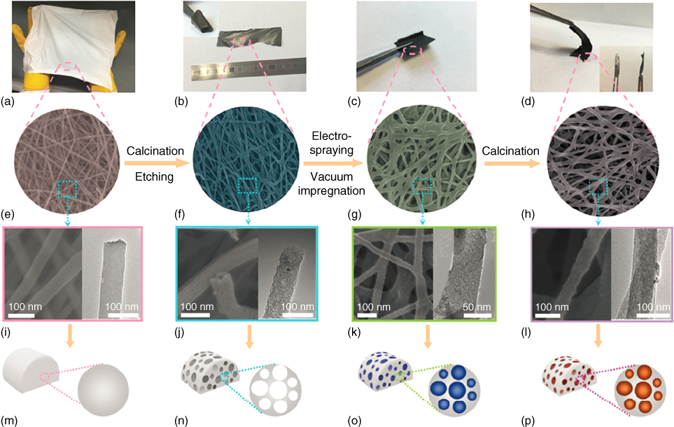
Figure 4.9 Fabrication of the alluaudite Na2+2xFe2−x(SO4)3@porous carbon nanofiber (PCNF) hybrid film. (a–d) Digital photos, (e–h) SEM images, (i–l) TEM images and (m–p) schematic illustrations of the (e–h) porous carbon nanofiber.
Source: Yu et al. 2016 [72]. Copyright 2016. Reproduced with permission from Royal Society of Chemistry.

Figure 4.10 Front view and side view of the flexible and binder‐free Na7V4(P2O7)4(PO4)/C nanorod–graphene thin film. (b) Temperature dependence of the electronic conductivity of the Na7V4(P2O7)4(PO4)/C nanorod–graphene film and the Na7V4(P2O7)4(PO4)/C nanorod pellet.
Source: Zhang et al. 2014 [73]. Copyright 2014. Reproduced with permission from Royal Society of Chemistry.
Prussian blue and its analogues perform as excellent alkali‐ion rechargeable battery electrodes owing to their inherently open framework structure with large interstitial sites, low cost, and easy accessibility [77, 78]. Importantly, Prussian blue analogues have been demonstrated as potential hosts for reversible di−/tri‐valent ion insertion, such as Mg2+, Ca2+, Pb2+, Zn2+, Al3+, and Y3+ in aqueous/nonaqueous electrolytes. However, their application is hampered by insufficient cycle life and low energy efficiency in nonaqueous electrolytes for SIBs, associated with the low electrical conductivity and structural imperfection. Zhang and coworkers reported a significant advance in the design and preparation of Prussian blue analogue FeFe(CN)6·xH2O nanoparticles on a flexible carbon fiber paper substrate as a binder‐free cathode in both organic and aqueous electrolytes by using a simple solution precipitation method [79]. Its sodium storage mechanism and improved electrochemical performance were examined by ex situ 57Fe Mossbauer spectroscopy and CV technology. With the merits of flexible structure and high conductivity, the resulting FeFe(CN)6·xH2O nanocomposite electrode exhibits a reversible specific capacity of 82 mAh g−1 at 0.2 C, excellent cycling performance for 1000 cycles with 81.2% capacity retention, and good high rate response up to 10 C.
In addition, sodium–air batteries have emerged as potential alternatives to lithium–air batteries owing to resource abundance, cost competition, safety, and environmental friendliness. Kim, Ko, and coworkers synthesized a binder‐free and robust electrode by directly growing hierarchical urchin‐shaped α‐MnO2 on rGO‐coated carbon microfiber (MGC) and used it as an air electrode for aqueous sodium–air battery [80]. Scanning electron microscopy (SEM) and transmission electron microscopy (TEM) images showed urchin‐shaped MnO2 microspheres composed of radially oriented MnO2 nanowires with diameters of 20–25 nm uniformly covered on the carbon fibers. Owing to the urchin‐shaped structure of the MnO2, high surface area and the superior electrocatalytic activity of the MGC, the assembled aqueous Na–air battery exhibited excellent recharge ability up to 20 cycles with a low over potential gap of 0.7 V and high round‐trip efficiency (81%), which is comparable to that of the battery using the noble metal Pt.
4.3.3 Organic Materials for Flexible SIBs
Organic electrode materials are attracting increasing attention as alternatives to conventional inorganic electrode materials due to their sustainability, universal availability, better compatibility with flexible substrates, and simpler packaging, which enable flexible SIBs to have better flexibility [81, 82]. Different from inorganic materials, which is naturally brittle, organic materials possess flexible and soft structures. The volume change of organic materials could be negligible after intercalation of sodium [83]. Although some innovative works have been developed in the design of organic material‐based SIBs, their performance is still far behind that of inorganic material‐based devices, especially in terms of cycling performance. It is very important to highlight that the physical and chemical properties of organic materials can be adjusted by chemical syntheses with different functional groups. The working voltage can be regulated through controlling the lowest unoccupied molecular orbital (LUMO) energies [84]. For example, adding electron‐donating (such as –ONa, –CH3, –NH2, etc.) or electron‐withdrawing (such as –F, –Cl, –Br, –NO2, –OCH3, etc.) groups, the LUMO energies can be rationally enhanced or lowered, thus leading to reduced or enhanced working voltage. Increasing the active groups can enhance the theoretical specific capacity. The dissolution in electrolyte can be inhibited by formatting salt or/and elevating the intermolecular forces. The conductivity can be enhanced by extending the conjugated structures in the core unit.
Quinone‐based organics is a promising cathode material for flexible SIBs. However, the most quinone‐based cathode usually suffers from low working voltage (under 2.5 V vs Na/Na+). Park, Kang, and coworkers reported a quinone‐derived organic cathode, tetrachloro‐1,4‐benzoquinone (C6Cl4O2), by introducing electronegative elements with high energy density of 580 Wh kg−1 and the highest working voltages among organic materials (2.72 V vs Na/Na+) [85]. Density functional theory (DFT) calculations demonstrated that the introduction of electronegative elements (here it is Cl) into the quinone structure lowered the LUMO energies of the C6Cl4O2, which in turn increased the sodium storage voltage [85]. To inhibit the dissolution of tetrachloro‐1,4‐benzoquinone, they incorporated C6Cl4O2 molecules into mesoporous carbon (CMK). The C6Cl4O2/CMK delivered higher capacity and longer cycling stability.
Most of the organic electrode materials were tested in a very slow charge/discharge rate (e.g. 10 mA g−1) and were observed to suffer from significant capacity degradation under high rate [86, 87], which is related to the low conductivity of organics. To improve the rate performance, Lei et al. reasonably designed sodium 4,4′‐stilbene‐dicarboxylate (SSDC) for anode material by extension of the π‐conjugated structure 88. As shown in Figure 4.11, the extension of the π‐conjugated system, SSDC, delivered a high reversible capacity of 220 mAh g−1 at a current density of 50 mA g−1. Even at ultrahigh current density of 10 A g−1, a reversible capacity of 72 mAh g−1can be obtained. The capacity retention is over 70% after 400 cycles at 1 A g−1. The wonderful electrochemical performance of SSDC, probably due to the extension of π‐conjugated structure can: (i) enhance the ion/electron transport and (ii) increase the stability of the charged and discharged states [88]. Recently, Lei and coworkers systematically investigated the important factors for high performance organic electrode materials by using disodium rhodizonate salt (DSR) as a model [84]. They found that the solubility, morphology, electrochemical window and binder are very important for high performance SIBs, especially, with high reversible capacity and long‐term cycling stability under fast‐charge/discharge reaction [84].
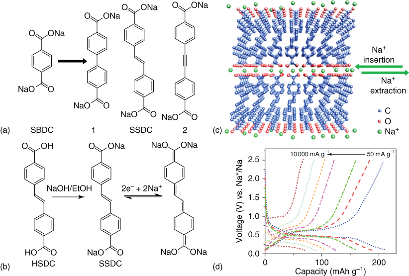
Figure 4.11 (a) Schematic chemical structure of starting molecule sodium benzene‐dicarboxylate (SBDC) and three possible linkages to extend its π‐conjugation, forming 1, SSDC, and 2, respectively. (b) Schematic diagram for the synthesis and reversible Na ion insertion/extraction mechanism of SSDC. (c) Schematic molecular packing of SSDC: the molecules are stacking layer‐by‐layer with strong π–π intermolecular interaction in plane and carboxylate group situated on the surface of the layers, forming a channel exactly at the active center for insertion/extraction of sodium ions between layers. (d) Rate capability of SSDC.
Source: Wang et al. 2015 [88]. Copyright 2015. Reproduced with permission from American Chemical Society.
4.3.4 Other Major Components for Flexible SIBs (Electrolyte, Separators, etc.)
Electrolytes and separators are also very important for flexible SIBs, especially in terms of safety, because flexible devices usually integrate with the human body. In conventional liquid organic electrolytes, sodium dendrite issue is an intractable problem, which will cause disastrous security problems. In this regard, solid electrolytes may be an ideal solution to these crucial issues.
Although solid‐state ceramic electrolytes have been developed for many years and show good safety in LIBs, they are inapplicable for flexible devices due to their rigid nature and low ionic conductivity (<0.1 mS cm−1) [89]. Gel polymer electrolytes (GPEs) may be a better choice for flexible SIBs, which usually consist of conventional liquid electrolytes and polymers with good mechanical strength and high ionic conductivity [90–92]. The polymers usually act as separators, while the liquid electrolytes act as charge carriers. Wu and coworkers [93] reported a sodium ion conducting gel polymer electrolyte (S‐GPE) based on poly(vinylidene difluoride‐co‐hexafluoropropylene), P(VDF‐HFP) porous membrane. Then the P(VDF‐HFP) membrane was soaked in conventional organic electrolyte to obtain the S‐GPE. The GPE possesses high ionic conductivity of 0.60 mS cm−1 at ambient temperature, good mechanical strength and thermostability, and high safety.
In order to further increase the ionic conductivity, developing a polymer/oxide composite membrane separator is an alternative strategy. Archer and coworkers [94] reported a sandwich‐type composite membrane by laminating a nanoporous sheet of γ‐Al2O3 with P(VDF‐HFP). Although the membrane had an acceptable ionic conductivity and a good mechanical modulus, it lacked flexibility [94]. Lately, Goodenough and coworkers [95] developed a polymer P(VDF‐HFP)‐polyvinylpyrrolidone (PVP)/Sb2O3 composite membrane separator for SIBs with ultraflexible, dendrite‐blocking and low‐cost characteristics (Figure 4.12). The larger particles of 5 μm Sb2O3 provide a better flexibility than a nanoporous sheet of γ‐Al2O3. The PVP forms pores that are large enough to incorporate an organic electrolyte and are small enough to retain the Sb2O3 particles [95]. The composite membrane separator has a wide electrolyte window, and wonderful mechanical and thermal stabilities when soaked with 1 M NaClO4ethylene carbonate/diethyl carbonate (EC/DEC) electrolyte. The sodium ion conductivity of this S‐GPE is 6.4 mS cm−1 at 25 °C. Even at 250 °C, the P(VDF‐HFP)‐(PVP)/Sb2O3 composite membrane is stable.
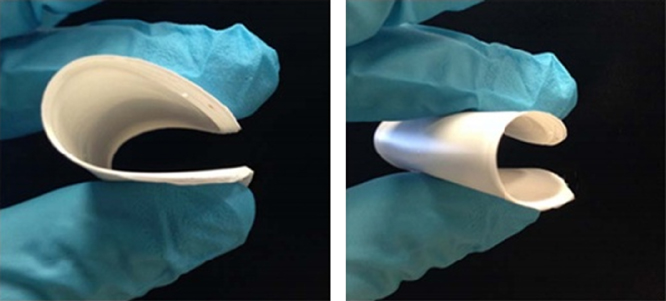
Figure 4.12 Digital picture of P(VDF‐HFP)‐ (PVP)/Sb2O3 composite membrane.
Source: Ansari et al. 2014 [95]. Copyright 2014. Reproduced with permission from The Electrochemical Society.
Although using oxides, such as Al2O3, SiO2, TiO2, etc., can improve the ionic conductivity of the polymer electrolytes 94, [96–98], this method also causes poor thermal and mechanical stability to some extent. To address this problem, using ionic liquids to replace the conventional metal oxides may be a good strategy due to their wide liquidus range, good electrochemical stability, high ionic conductivity, and excellent thermal stability. Besides, ionic liquids also can act as the supplier of free ion charge carriers. Singh et al. [98] developed a novel S‐GPE membrane based on polymer, poly(ethyleneoxide) (PEO); ionic liquid, 1‐butyl‐3‐methylimidazolium methylsulfate (BMIM‐MS); and sodium salt, sodium methyl sulfate salt (NaMS), by solution cast technique. The as‐prepared polymer electrolyte membranes are free‐standing and flexible with good mechanical stability. This optimized polymer electrolyte shows high electrochemical potential window of 4–5 V with good thermal stability over 300 °C [98].
4.4 Design of Full Cell for Flexible SIBs
We have reviewed the development of the major components for flexible SIBs. Next, we will focus on the design of full cell for SIBs. There is an urgent need but it is also a critical challenge to design flexible SIBs full cell with high performance.
Cui and coworkers first prepared a flexible porous polyimide graphite film (PGF) by laser drilling pore technique [99]. The PGF possesses considerable mechanical strength, high planar electrical conductivity, and enhanced diffusion kinetics. They further designed a novel full cell based on PGF anode and Na3V2(PO4)3 cathode. The electrolyte is 1 M NaPF6 in diglyme. This unique energy storage system makes the best of co‐intercalation behavior of sodium ion and solvent into a porous PGF host. The SIB full cell delivers improved energy density of 130.7 Wh kg−1 based on the total electrode materials and prolonged cycling behavior of over 500 cycles. The porous PGF is flexible, but the full cell is also rigid. Yan and coworkers [100] reported a flexible full cell assembled with N‐doped carbon sheets (NDCS)//Na3V2(PO4)3(NVP) with a voltage window of 0.7–4.2 V. The anode material, NDCS, with a high N content of about 9.89 at.% was prepared by using biomass byproduct okara as the sources of both C and N [100]. The cathode material NVP was synthesized by the solution‐based carbo‐thermal reduction method, which delivered 99.5 mAh g−1 with the plateau of 3.6 V. The full cell delivered a stable capacity of 103 mAh g−1at the current density of 1.5 C (1 C = 375 mA g−1) where the electrolyte was 1 M NaClO4 in propylene carbonate (PC) and fluoroethylene carbonate (FEC, 5%). It is important to highlight that the NDCS//NVP was easy to power a wearable light‐emitting diode (LED) screen, as can be seen in Figure 4.13a,b.
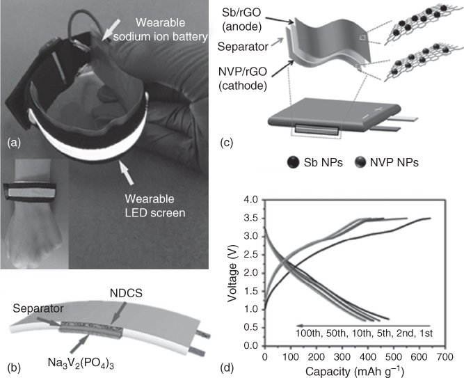
Figure 4.13 (a) The flexible SIB full cell (NDCS//NVP) was linked to a flexible/wearable LED screen. (b) The schematic plan of full cell assembled with NDCS//NVP. (c) Schematic illustration for the fabrication of the flexible Sb/rGO//NVP/rGO SIB full cell. (d) Galvanostatic charge/discharge curves at a current density of 100 mA g−1 over the voltage range of 0.7–3.5 V.
Source: Zhang et al. 2015 [101]. Copyright 2015. Reproduced with permission from John Wiley and Sons.
Source: Yang et al. 2016 [100]. Copyright 2016. Reproduced with permission from John Wiley and Sons.
Hu and coworkers [101] designed the flexible and binder‐free anode and cathode of nanocomposites of Sb/rGO and NVP/rGO for flexible SIBs. The unique interconnected electrode network, excellent electrical conductivity, and homogenous loading of Sb and NVP nanoparticles enable short ion/electron transport path and volume flexibility, thus leading to superior reversible capacities and cycling stability. As shown in Figure 4.13c,d, the flexible SIB, which was fabricated by soft package technology, delivered a high capacity of 400 mAh g−1 at 100 mA g−1 after 100 cycles. Later, Chen and coworkers [102] assembled a flexible sodium ion full battery with MnFe2O4(MFO)@C//Na3V2(PO4)2F3 (NVPF)/C using a similar Al‐plastic soft package technology, as shown in Figure 4.14a,b. The MFO@C nanofibers, MFO nanodots encapsulated in porous N‐doped carbon nanofibers, were prepared by an electro‐spinning strategy, which can be directly employed as flexible free‐standing anode with ultrahigh rate character of 305 mAh g−1 even at 10 A g−1 and ultralong cycling life over 4200 cycles. When combined with NVPF/C cathode at an optimized electro‐active material mass ratio of anode to cathode at 1 : 5, the flexible SIB delivered a stable capacity of 400 mAh g−1 based on MFO@C and a high energy density of 77.8 Wh kg−1 based on the total mass of the flexible SIB (6.72 g in this work) [102].

Figure 4.14 (a) SEM image and digital photo (inset) of the MFO@C electrode charged at 3.0 V after 300 cycles. (b) Charge/discharge curves of flexible SIB full cell with (MFO)@C//NVPF/C. (c) SEM images of NTO/CT composite. (d) Capacitance retention of flexible NIC measured under different bent conditions.
Source: Dong et al. 2016 [11]. Copyright 2016. Reproduced with permission from John Wiley and Sons.
Source: Liu et al. 2016 [102]. Copyright 2016. Reproduced with permission from American Chemical Society.
Recently, Zhang and coworkers [11] developed a novel sodium ion energy storage device, called flexible sodium ion capacitor (SIC), based on flexible Na2Ti3O7 nanosheets/carbon texibles (NTO/CT) anode and flexible reduced graphene oxide films (GFs) cathode. In this flexible device, sodium ions are intercalated into NTO/CT anodes during charging; meanwhile, anions (ClO4− in this work) are adsorbed on the surface of the GFs cathode [11]. The above process is reversed during the discharge process. This novel device integrated the advantages of both flexible SIBs and flexible supercapacitors. The flexible NTO/CTs//GFs configuration was sealed with PDMS with a voltage window of 1–3 V. Taking the fully packed flexible SIC into consideration, the volumetric energy density and power density can reach up to 1.3 mWh cm−3 and 70 mW cm−3, respectively. It must also be mentioned that the flexible device exhibited a stable electrochemical performance even under various mechanical deformation (Figure 4.14c,d).
Safety is also a key issue for flexible energy storage device in practical applications. However, all the above mentioned flexible sodium ion energy storage devices use the liquid electrolytes, where sodium salt dissolved into organic solvent. When flexible devices are assembled with liquid organic electrolyte, it may give rise to leakage or produce a short circuit in the resulting flexible energy storage devices under mechanical deformation. In this regard, developing solid electrolytes would be a perfect solution to these crucial issues. Therefore, Zhang, Yu, and coworkers. [103] designed a flexible quasi‐solid‐state sodium ion capacitor (QSS‐SIC) based on urchin‐like NTO anode and peanut shell derived carbon (PSC) cathode with a kind of sodium ion conducting gel polymer as the separator and electrolyte. Such QSS‐SIC can exhibit high‐energy and high‐power characteristics and long cycling life because of the integrated storage mechanisms of batteries and supercapacitors. Based on the total mass of the electrode materials, the energy density and power density can reach to 111.2 Wh kg−1 and 11 200 W kg−1, respectively. The QSS‐SIC also delivers a wonderful cycling stability with capacity retention of 86% after 3000 cycles. Furthermore, a flexible QSS‐SIC was fabricated by using foil/poly bag film as the package material. It is robust enough to operate under various deformations without significant capacity loss (Figure 4.15) [103]. These findings provide a common strategy for the development of flexible quasi‐solid‐state energy storage devices. Kim and coworkers [104] reported a NASICON (Na3Zr2Si2PO12)‐based hybrid solid electrolyte (HSE) for flexible solid‐state SIBs for the first time. The HSE shows low interface resistance and high thermal and electrochemical stability. A pouch‐type flexible solid‐state sodium ion full cell was fabricated comprising NaFePO4/HSE/hard carbon (HC) and using carbon paper as flexible current collector [104]. The NaFePO4/HSE/HC full cell has an average voltage of 2.6 V and achieves a high reversible capacity of 120 mA h g−1. After 200 cycles, it also delivers good capacity retention of 96%. When the solid‐state full cell is bent several times, it can continue to power an LED lamp. This means that the flexible solid‐state sodium ion full cell possesses wonderful mechanical deformability.

Figure 4.15 (a) Schematic illustration of the structure of the flexible quasi‐solid‐state SIC. (b) Diagram of the flexible QSS‐SIC under various bending conditions. (c) Stability of capacitive performance of the QSS‐SIC collected at different bending conditions. (d) A commercial desk lamp and a UT capacitor logo consisting of 50 red LEDs powered by the assembled QSS‐SIC under rolled state.
Source: Li et al. 2016 [103]. Copyright 2016. Reproduced with permission from American Chemical Society.
Recently, Yu and coworkers reported an all‐stretchable‐component SIB full cell based on graphene‐modified PDMS sponge electrodes and an elastic gel membrane [105]. This full cell delivered high capacity, good rate capability, long cycling stability, and good mechanical deformation.
4.5 Summary and Outlook
Without doubt, flexible SIBs have become a kind of competitive flexible energy storage devices for flexible and wearable electronic applications in the near future. The key scientific issues and the progress that have been achieved according to the design of electro‐active materials, exploration of electrode structure, and fabrication of full cell, and so on have been highlighted. As compared with conventional energy storage devices, in order to realize flexibility of SIBs, the main components should be flexibility and stretchability, as well as the anode, cathode, electrolyte, current collector, and packaging materials. Although some achievements have been made, current flexible SIBs are still far away from satisfying the requirements for flexible and wearable electronic devices. The development in the field of flexible SIB systems is still at the early stage of academic validation. Hence, exploring novel approaches for flexible SIBs remains a greatly academic and industrial challenge. In order to improve the energy density, power density, and reliability of flexible SIBs, several areas can be investigated as follows.
- Developing advanced electro‐active materials with satisfactory electrochemical performance. The most commonly used methods include design of nanostructure, conductive coating, and doping with hetero‐atoms. Compared with brittle inorganic materials, organic electrode materials have better compatibility with flexible devices, possibly simpler packaging and lower cost. In addition, with rational design, organic materials are able to achieve competitive electrochemical performance.
- Design of innovative electrode structure with admirable mechanical and chemical stability. At present, the major works just focus on design of nanomaterials grown on bendable substrates or as composites. The stretchability and compressibility are still unsatisfied. In order to develop the advanced electrode structure with wonderful bendability as well as stretchability and compressibility, new processes for fabricating flexible electrodes, such as lithography and 3D printing, are needed.
- Flexible SIBs must sustain severe mechanical deformations that also need advanced flexible electrolytes. Besides, safety is another very important factor for flexible energy storage devices in practical applications. Compared with conventional organic liquid electrolyte, solid‐state electrolytes possess better safety and compatibility. However, flexible solid‐state electrolytes that have comparable ionic conductivity with liquid electrolyte have not yet been realized.
- Currently, packaging materials, especially for stretchable packages, with flexible and stretchable features have not attracted sufficient attention. Therefore, modification of reliable packaging materials and optimization of device structures to protect the integrity of energy storage system under various environments should also be considered urgently.
- Moreover, the development of flexible micro‐SIBs with enhanced electrochemical characters also plays an interesting direction in miniaturized flexible energy storage applications, such as microelectronics, microdisplay, implantable medical devices, etc.
- Modern portable flexible devices not only strongly rely on flexible energy storage devices, but also urgently need multifunctional devices. Integration of flexible SIBs with other components, for example, with solar cells or sensors, will be very attracting.
Although there are enormous challenges, advanced flexible SIBs with unique properties will provide promising applications in flexible and wearable electronics field in the near future.
References
- 1 El‐Kady, M.F., Strong, V., Dubin, S., and Kaner, R.B. (2012). Science 335: 1326.
- 2 Li, L., Wu, Z., Yuan, S., and Zhang, X.‐B. (2014). Energy Environ. Sci. 7: 2101.
- 3 Bao, Z. and Chen, X. (2016). Adv. Mater. 28: 4177.
- 4 Sasaki, T., Ukyo, Y., and Novák, P. (2013). Nat. Mater. 12: 569.
- 5 Shen, L., Dong, S., Zhang, X., and Cao, G. (2017). Black TiO2 Nanomaterials for Energy Applications, 249–273. World Scientific.
- 6 Kim, H., Kim, H., Ding, Z. et al. (2016). Adv. Energy Mater. 6: 1600943.
- 7 Luo, W., Shen, F., Bommier, C. et al. (2016). Acc. Chem. Res. 49: 231.
- 8 Guo, S., Yi, J., Sun, Y., and Zhou, H. (2016). Energy Environ. Sci. 9: 2978.
- 9 Pan, H., Hu, Y.‐S., and Chen, L. (2013). Energy Environ. Sci. 6: 2338.
- 10 Slater, M.D., Kim, D., Lee, E., and Johnson, C.S. (2013). Adv. Funct. Mater. 23: 947.
- 11 Dong, S., Shen, L., Li, H. et al. (2016). Adv. Funct. Mater. 26: 3703.
- 12 Kim, S.W., Seo, D.H., Ma, X. et al. (2012). Adv. Energy Mater. 2: 710.
- 13 Zhang, Y., Zhao, Y., Ren, J. et al. (2015). Adv. Mater. 28: 4524.
- 14 Dong, S., Shen, L., Li, H. et al. (2015). J. Mater. Chem. A 3: 21277.
- 15 Wen, L., Li, F., and Cheng, H.M. (2016). Adv. Mater. 28: 4306.
- 16 Zhao, Q., Lu, Y., and Chen, J. (2016). Adv. Energy Mater. doi: 10.1002/aenm.201601792.
- 17 Hu, Y., Zhao, T., Zhu, P. et al. (2016). J. Mater. Chem. C 4: 5839.
- 18 Shen, L., Che, Q., Li, H., and Zhang, X. (2014). Adv. Funct. Mater. 24: 2630.
- 19 Xu, J., Wang, Q., Wang, X. et al. (2013). ACS Nano 7: 5453.
- 20 Xue, J., Zhao, Y., Cheng, H. et al. (2013). Phys. Chem. Chem. Phys. 15: 8042.
- 21 Shao, Y., El‐Kady, M.F., Wang, L.J. et al. (2015). Chem. Soc. Rev. 44: 3639.
- 22 Kim, S.D., Rana, K., and Ahn, J.‐H. (2016). J. Mater. Chem. A 4: 19197.
- 23 Suo, Z., Ma, E., Gleskova, H., and Wagner, S. (1999). Appl. Phys. Lett. 74: 1177.
- 24 Wong, W.S. and Salleo, A. (2009). Flexible Electronics: Materials and Applications. Springer Science & Business Media.
- 25 Shi, G., Zhao, Z., Pai, J.H. et al. (2016). Adv. Funct. Mater. 26: 7614.
- 26 Zhang, Y., Huang, Y., and Rogers, J.A. (2015). Curr. Opin. Solid State Mater. Sci. 19: 190.
- 27 Peng, H. (2015). Fiber‐Shaped Energy Harvesting and Storage Devices. Springer.
- 28 Song, J. (2015). Curr. Opin. Solid State Mater. Sci. 19: 160.
- 29 Liu, W., Chen, Z., Zhou, G. et al. (2016). Adv. Mater. 28: 3578.
- 30 Shen, L., Wang, J., Xu, G. et al. (2015). Adv. Energy Mater. 5: 1400977.
- 31 Pang, G., Nie, P., Yuan, C. et al. (2014). J. Mater. Chem. A 2: 20659.
- 32 Cao, W., Luo, J., Yan, J. et al. (2017). J. Electrochem. Soc. 164: A93.
- 33 Li, N., Chen, Z., Ren, W. et al. (2012). Proc. Natl. Acad. Sci. U.S.A. 109: 17360.
- 34 Kokkinis, D., Schaffner, M., and Studart, A.R. (2015). Nat. Commun. 6: 8643.
- 35 MacDonald, E. and Wicker, R. (2016). Science 353: aaf2093.
- 36 Wen, Y., He, K., Zhu, Y. et al. (2014). Nat. Commun. 5: 4033.
- 37 Cao, Y., Xiao, L., Sushko, M.L. et al. (2012). Nano Lett. 12: 3783.
- 38 Li, W., Zeng, L., Yang, Z. et al. (2014). Nanoscale 6: 693.
- 39 David, L. and Singh, G. (2014). J. Phys. Chem. C 118: 28401.
- 40 Deng, X., Xie, K., Li, L. et al. (2016). Carbon 107: 67.
- 41 Hu, X., Zhang, W., Liu, X. et al. (2015). Chem. Soc. Rev. 44: 2376.
- 42 Liu, Y., He, X., Hanlon, D. et al. (2016). ACS Nano 10: 8821.
- 43 David, L., Bhandavat, R., and Singh, G. (2014). ACS Nano 8: 1759.
- 44 Li, Y., Zhu, H., Shen, F. et al. (2015). Nano Energy 13: 346.
- 45 Xie, X., Makaryan, T., Zhao, M. et al. (2015). Adv. Energy Mater. 6: 1502161.
- 46 Xiang, J., Dong, D., Wen, F. et al. (2016). J. Alloy. Compd. 660: 11.
- 47 Zhang, Y., Liu, Z., Zhao, H., and Du, Y. (2016). RSC Adv. 6: 1440.
- 48 Xia, W., Xu, F., Zhu, C. et al. (2016). Nano Energy 27: 447.
- 49 Li, Y., Wang, D., An, Q. et al. (2016). J. Mater. Chem. A 4: 5402.
- 50 Wei, X., Li, W., Shi, J.‐A. et al. (2015). ACS Appl. Mater. Interfaces 7: 27804.
- 51 Luo, B., Qiu, T., Ye, D. et al. (2016). Nano Energy 22: 232.
- 52 Zhao, M., Zhao, Q., Qiu, J. et al. (2016). RSC Adv. 6: 95449.
- 53 Xu, W., Zhao, K., Zhang, L. et al. (2016). J. Alloy. Compd. 654: 357.
- 54 Liu, Y., Zhang, N., Jiao, L., and Chen, J. (2015). Adv. Mater. 27: 6702.
- 55 Zhu, Y., Han, X., Xu, Y. et al. (2013). ACS Nano 7: 6378.
- 56 Sun, J., Lee, H.‐W., Pasta, M. et al. (2016). Energy Storage Mater. 4: 130.
- 57 Zhang, C., Wang, X., Liang, Q. et al. (2016). Nano Lett. 16: 2054.
- 58 Koo, B., Chattopadhyay, S., Shibata, T. et al. (2013). Chem. Mater. 25: 245.
- 59 Sun, B., Bao, S.J., Le Xie, J., and Li, C.M. (2014). RSC Adv. 4: 36815.
- 60 Wang, X., Liu, Y., Wang, Y., and Jiao, L. (2016). Small 12: 4865.
- 61 Xu, Y., Lotfabad, E.M., Wang, H. et al. (2013). Chem. Commun. 49: 8973.
- 62 González, J.R., Alcántara, R., Nacimiento, F. et al. (2014). CrystEngComm 16: 4602.
- 63 Zhu, X., Li, Q., Fang, Y. et al. (2016). Part. Part. Syst. Char. doi: 10.1002/ppsc.201500216.
- 64 Doeff, M.M., Cabana, J., and Shirpour, M. (2014). J. Inorg. Organomet. Polym Mater. 24: 5.
- 65 Senguttuvan, P., Rousse, G.L., Seznec, V. et al. (2011). Chem. Mater. 23: 4109.
- 66 Wang, W., Yu, C., Lin, Z. et al. (2013). Nanoscale 5: 594.
- 67 Li, Z., Shen, W., Wang, C. et al. (2016). J. Mater. Chem. A 4: 17111.
- 68 Trinh, N.D., Crosnier, O., Schougaard, S.B., and Brousse, T. (2011). ECS Trans. 35: 91.
- 69 Rudola, A., Saravanan, K., Devaraj, S. et al. (2013). Chem. Commun. 49: 7451.
- 70 Wang, X., Li, Y., Gao, Y. et al. (2015). Nano Energy 13: 687.
- 71 Yang, D., Liao, X.‐Z., Shen, J. et al. (2014). J. Mater. Chem. A 2: 6723.
- 72 Yu, T., Lin, B., Li, Q. et al. (2016). Phys. Chem. Chem. Phys. 18: 26933.
- 73 Zhang, S., Deng, C., and Meng, Y. (2014). J. Mater. Chem. A 2: 20538.
- 74 Xu, X., An, Q., and Mai, L. (2016). Phys. Chem. Chem. Phys. 18: 12074.
- 75 Balogun, M.‐S., Luo, Y., Lyu, F. et al. (2016). ACS Appl. Mater. Interfaces 8: 9733.
- 76 Rui, X., Tang, Y., Malyi, O.I. et al. (2016). Nano Energy 22: 583.
- 77 Wu, X., Luo, Y., Sun, M. et al. (2015). Nano Energy 13: 117.
- 78 Jiang, Y., Yu, S., Wang, B. et al. (2016). Adv. Funct. Mater. 26: 5315.
- 79 Nie, P., Shen, L., Pang, G. et al. (2015). J. Mater. Chem. A 3: 16590.
- 80 Khan, Z., Park, S., Hwang, S.M. et al. (2016). NPG Asia Mater. 8: e294.
- 81 Wang, Y., Ding, Y., Pan, L. et al. (2016). Nano Lett. 16: 3329.
- 82 Wu, S., Wang, W., Li, M. et al. (2016). Nat. Commun. 7: 13318.
- 83 Wang, C., Jiang, C., Xu, Y. et al. (2016). Adv. Mater. 28: 9182.
- 84 Wang, C., Fang, Y., Xu, Y. et al. (2016). Adv. Funct. Mater. 26: 1777.
- 85 Kim, H., Kwon, J.E., Lee, B. et al. (2015). Chem. Mater. 27: 7258.
- 86 Castillo‐Martínez, E., Carretero‐González, J., and Armand, M. (2014). Angew. Chem. Int. Ed. 53: 5341.
- 87 Luo, W., Allen, M., Raju, V., and Ji, X. (2014). Adv. Energy Mater. 4: 1400554.
- 88 Wang, C., Xu, Y., Fang, Y. et al. (2015). J. Am. Chem. Soc. 137: 3124.
- 89 Quartarone, E. and Mustarelli, P. (2011). Chem. Soc. Rev. 40: 2525.
- 90 Terabe, K., Hasegawa, T., Nakayama, T., and Aono, M. (2005). Nature 433: 47.
- 91 Zhou, L., Cao, Q., Jing, B. et al. (2014). J. Power Sources 263: 118.
- 92 Cao, C., Liu, W., Tan, L. et al. (2013). Chem. Commun. 49: 11740.
- 93 Yang, Y., Chang, Z., Li, M. et al. (2015). Solid State Ionics 269: 1.
- 94 Tu, Z., Kambe, Y., Lu, Y., and Archer, L.A. (2014). Adv. Energy Mater. 4: 1300654.
- 95 Ansari, Y., Guo, B., Cho, J.H. et al. (2014). J. Electrochem. Soc. 161: A1655.
- 96 Rajendran, S., Sivakumar, M., and Subadevi, R. (2004). Mater. Lett. 58: 641.
- 97 Appetecchi, G., Croce, F., and Scrosati, B. (1995). Electrochim. Acta 40: 991.
- 98 Singh, V.K., Chaurasia, S.K., and Singh, R.K. (2016). RSC Adv. 6: 40199.
- 99 Han, P., Han, X., Yao, J. et al. (2015). Electrochem. Commun. 61: 84.
- 100 Yang, T., Qian, T., Wang, M. et al. (2016). Adv. Mater. 28: 539.
- 101 Zhang, W., Liu, Y., Chen, C. et al. (2015). Small 11: 3822.
- 102 Liu, Y., Zhang, N., Yu, C. et al. (2016). Nano Lett. 16: 3321.
- 103 Li, H., Peng, L., Zhu, Y. et al. (2016). Nano Lett. 16: 5938.
- 104 Kim, J.‐K., Lim, Y.J., Kim, H. et al. (2015). Energy Environ. Sci. 8: 3589.
- 105 Li, H., Ding, Y., Ha, H. et al. (2017). Adv. Mater. 29: 1700898.