

GDPS extensions for heterogeneous systems and data
Most enterprises today have a heterogeneous IT environment where the applications and data reside on a variety of hardware and software platforms, such as IBM System z, IBM System p, UNIX, Windows, and Linux. Such an environment can benefit greatly if there is a single point of control to manage the data across all the platforms, and for the disaster recovery solution to coordinate the recovery across multiple platforms.
In this chapter we describe the various GDPS extensions that are available for clients to manage data and coordinate disaster recovery across multiple platforms. The various extensions are available in one or more of the GDPS offerings. The extensions described in this chapter are:
•Open LUN Management function
Available for GDPS/PPRC, GDPS/PPRC HyperSwap Manager, and GDPS/Global Mirror
•GDPS/PPRC Multiplatform Resiliency for System z (also known as xDR)
Available for GDPS/PPRC
•Distributed Cluster Management support for Veritas Cluster Servers (VCS)
Available for GDPS/PPRC, GDPS/XRC, and GDPS/GM
•Distributed Cluster Management support for Tivoli System Automation Application Manager (SA AppMan)
Available for GDPS/PPRC and GDPS/GM
8.1 Open LUN Management function
As discussed in 3.1.3, “Protecting distributed (FBA) data” on page 62, many enterprises today run applications that update data across multiple platforms. For these enterprises there is a need to manage and protect not only the System z data, but also the data residing on the non System z servers. GDPS/PPRC, GDPS/PPRC HyperSwap Manager, and GDPS/Global Mirror have been extended to manage a heterogeneous environment of System z and distributed systems data by providing a function called Open LUN Management.
The Open LUN Management function allows GDPS to be a single point of control to manage business resiliency across multiple tiers in the infrastructure, thus improving cross-platform system management and business processes. If installations share their disk subsystems between the System z and distributed systems platforms, GDPS/PPRC and GDPS/Global Mirror can manage the Metro Mirror or Global Mirror remote copy configurations and the FlashCopy for distributed systems storage.
Open LUN support extends the GDPS/PPRC Freeze capability to Open LUN (FBA) devices residing in supported disk subsystems to provide data consistency for not only the System z data, but also the data on Open LUNs. If you are using the GDPS/PPRC function known as xDR (described in 8.2, “GDPS/PPRC Multiplatform Resiliency for System z” on page 216), GDPS also supports native Linux for System z systems running on SCSI-attached Fixed Block Architecture (FBA or FB) disks. In addition to providing the Freeze capability for FBA disks, GDPS supports planned and unplanned HyperSwap for the FB disks used by xDR-managed native Linux systems.
In an Open LUN configuration, you can select one of the following two options to specify how Freeze and HyperSwap processing are to be handled for Open LUN (FB disks) and System z (CKD disks), when mirroring or primary disk problems are detected:
|
Note: Irrespective of the option you select, CKD and xDR FB disks are always in the same consistency group; they are always frozen and swapped together. The freeze and swap policy options that you select are applied to the CKD and xDR FB disks together.
|
•You can select to Freeze all devices managed by GDPS.
If this option is used, both the CKD and FBA devices are in a single consistency group. Any Freeze trigger, either for the System z or Open LUN devices, will result in both the Open LUN and the System z LSSs managed by GDPS being frozen. This option allows you to have consistent data across heterogeneous platforms in the case of a disaster, thus allowing you to restart systems in the site where secondary disks are located. This option is especially appropriate when there are distributed units of work on System z and distributed servers that update the same data, for example using IBM DB2 DRDA®, the IBM Distributed Relational Database Architecture™.
•You can select to Freeze devices by group.
If this option is selected, the CKD and xDR controlled FBA devices are in a separate consistency group from the non-xDR FBA devices. The Freeze will only be performed on the group for which the Freeze trigger was received. If the Freeze trigger occurs for a System z disk device, only the CKD and xDR controlled FBA devices will be frozen. If the trigger occurs for an non-xDR controlled FBA disks, only they will be frozen.
The Global Mirror remote copy technology, described in 2.4.3, “Global Mirror” on page 31, inherently provides data consistency for both System z and distributed systems data.
Open LUN (FB disk) management prerequisites
GDPS requires the disk subsystems containing the FB devices to support specific architectural features. These architectural features are supported by all IBM disk subsystems:
•The ability to manage FB devices through a CKD utility devices
GDPS runs on z/OS and can therefore communicate directly over a channel connection to CKD devices only. To communicate commands to the FB LSS and devices, the PPRC architecture allows using a CKD utility device in the same disk subsystem as a go-between to send commands and to monitor and control the mirroring of the FB devices. GDPS will need at least one CKD utility device in each hardware cluster of the storage subsystem where FB devices are located. A sample example of this function called Open LUN Management is shown in Figure 8-1.
•The ability to send SNMP traps to report certain errors
The FB LSS and devices must communicate certain error conditions back to GDPS (for example, suspension of an FB device pair in GDPS/PPRC or GDPS/PPRC HM or an abnormal state of a Global Mirror session in GDPS/GM). Such status is communicated to the z/OS host that is running the GDPS Controlling system through an IP connection using SNMP traps. GDPS captures these traps and drives autonomic action such as performing a freeze for a mirroring failure.
A sample Open LUN GDPS/PPRC configuration is shown in Figure 8-1. Not shown in this picture are the IP connections from the attached disks to the z/OS host where GDPS is running.

Figure 8-1 Open LUN support
Refer to 8.3, “Distributed Cluster Management” on page 222 if you are interested in managing not just replication, but also management of the systems and the recovery of the systems that use FB disks.
Also, note that GDPS/PPRC (or GDPS/PPRC HM) HyperSwap involves changing information at the control block level within the operating system on any system using the disks being swapped. GDPS/PPRC supports HyperSwap for FB devices used by native Linux on System z systems managed by xDR. Refer to 8.2.2, “Native Linux on System z” on page 219. Otherwise, HyperSwap for FB disks are not supported.
8.2 GDPS/PPRC Multiplatform Resiliency for System z
|
Note: For the remainder of this section, Linux on System z might also be referred to as Linux. The terms are used interchangeably.
|
As discussed in 3.3.1, “Multiplatform Resiliency for System z (also known as xDR)” on page 69, when clients implement a multitiered architecture, with application servers that run on Linux on System z and database servers that run on z/OS, there is a need to provide a coordinated near-continuous availability and disaster recovery solution for both z/OS and Linux. GDPS/PPRC provides this capability with a function called “Multiplatform Resiliency for System z (also known as xDR)”. To provide these capabilities, GDPS/PPRC communicates and coordinates with System Automation for MultiPlatforms (SA MP) running on Linux on System z.
Linux can run either of the following ways:
•As a guest under z/VM
•Native in a System z partition
From a GDPS-perspective, this is not an either/or proposition. The same instance of GDPS/PPRC can manage one or more z/VM systems and one or more native Linux on System z systems in addition to z/OS systems.
Note also that it is not mandatory to have any z/OS production systems managed by GDPS. The only z/OS systems that are mandatory are the GDPS Controlling systems. Using one or preferably two z/OS systems, you can manage a production environment that is solely composed of z/VM and/or native Linux on System z systems.
Most xDR functions can only be performed by a GDPS Controlling system. We highly recommend that GDPS/PPRC environments managing xDR systems are configured with two Controlling systems.
8.2.1 Guest Linux under z/VM
In a GDPS xDR-managed z/VM system you must configure a special Linux guest, which is known as the proxy guest. The proxy is a guest that is dedicated to providing communication and coordination with the GDPS/PPRC Controlling system, and must run System Automation for MultiPlatforms.
The proxy guest serves as the middleman for GDPS. It communicates commands from GDPS to z/VM, monitors the z/VM environment, and communicates status information and failure information such as a HyperSwap trigger affecting z/VM disk back to the GDPS/PPRC Controlling system. GDPS/PPRC uses SA MP to pass commands to z/VM and Linux guests.
GDPS xDR supports definition of two proxy nodes for each z/VM host; one proxy node running on Site1 disk and the other running on Site2 disk. This support extends the two-Controlling system model to the xDR proxy nodes, thus providing a high availability proxy design. At any given time, the proxy node running on disk in the PPRC secondary site is the Master proxy, and this is the proxy node that the GDPS Master Controlling system coordinates actions with. Similar to the Controlling system Master role, the proxy node Master role is switched automatically when PPRC disk is switched (or recovered) or when the Master proxy fails.
The disks being used by z/VM, the guest machines, and the proxy guest in this configuration must be CKD disks.
|
Note: Most xDR functions, including HyperSwap, benefit non-Linux guests of z/VM as well. In fact, it is possible that you have no “production” Linux guests at all. The only requirement for Linux guests is for the xDR proxy nodes, which must be dedicated Linux guests.
Be aware, however, that a z/VM host running z/OS guest(s) is not supported by xDR.
|
z/VM provides a HyperSwap function. With this capability, the virtual device associated with one real disk can be swapped transparently to another disk. GDPS/PPRC coordinates planned and unplanned HyperSwap for both z/OS and z/VM disks, providing continuous data availability spanning the multitiered application. It does not matter whether the first disk failure is detected for a z/VM disk or a z/OS disk; all are swapped together.
For site failures, GDPS/PPRC provides a coordinated Freeze for data consistency across z/VM and z/OS. Again, it does not matter whether the first freeze trigger is captured on a z/OS disk or a z/VM disk; all will be frozen together.
System and hardware management capabilities similar to those available for z/OS systems are also available for z/VM systems. GDPS xDR can perform a graceful shutdown of z/VM and its guests and perform hardware actions such as LOAD and RESET against the z/VM system’s partition. GDPS supports taking a stand-alone dump of a z/VM system. As previously described, GDPS can manage CBU/OOCoD for IFLs and CPs on which z/VM systems are running.
Figure 8-2 shows an example of a configuration where several Linux nodes are running as guests under z/VM. Note that one of the Linux guests is the proxy. The non-proxy SAP Linux guests are shown as also running SA MP. This is not mandatory. If you do run SA MP in the production Linux guest systems, GDPS provides additional capabilities for such guests. The figure also illustrates the actions taken if a disk failure is detected and HyperSwap is invoked by GDPS/PPRC.

Figure 8-2 HyperSwap example - Linux running as a guest under z/VM
GDPS controlled shutdown of z/VM
Graceful shutdown of a z/VM system involves multiple virtual servers. This is a rather complex process and GDPS has special automation to control this shutdown. The GDPS automated process occurs in multiple phases:
•During the first phase, all the SA MP clusters with all the nodes for these clusters are stopped. The master proxy is the only guest running SA MP that is not stopped. When all clusters and nodes running SA MP have been successfully stopped, GDPS proceeds to the next phase.
•During the second phase all remaining guests that are capable of processing the shutdown signal are stopped.
•In phase three, the master proxy server and z/VM are shut down.
When an xDR-managed z/VM system is shut down using the GDPS Stop Standard Action (or equivalent script statement), all xDR-managed guests are stopped in parallel. GDPS provides the ability to control the sequence in which you stop guest systems during a z/VM shutdown.
GDPS/PPRC xDR support for z/VM Single System Image clustering
z/VM introduced Single System Image (SSI) clustering whereby four z/VM systems can be clustered to provide more effective resource sharing and other capabilities.
GDPS xDR supports z/VM systems that are members of an SSI cluster. GDPS will be aware of the fact that a z/VM system is a member of an SSI. This allows GDPS to perform certain system control actions for these z/VM systems correctly, observing SSI rules.
Linux guests can be transparently moved from one z/VM system in an SSI cluster to another, that is, without requiring the guest to be stopped. This capability, which is called Live Guest Relocation, provides continuous availability for Linux guests of z/VM in planned outage situations. If a z/VM system is going to be shutdown, for example for disruptive software maintenance, the relocateable Linux guests can first be moved to other z/VM systems in the cluster, avoiding an outage to these guests. Similarly, for an entire site shutdown, the guests under all z/VM systems in the site to be shutdown can first be moved to z/VM systems in the other site.
GDPS provides support for performing Live Guest Relocation for xDR-managed z/VM systems. GDPS provides a relocation test capability that tries to assess whether a particular relocation action is likely to be successful or not. For example, the target z/VM system might not have sufficient resources to host the guest to be moved. Such a test function is quite useful because it will allow you to rectify potential problems before they are encountered. GDPS management for CPs and IFLs using On/Off Capacity on Demand is complementary to this function. You can use GDPS to first increase IFL capacity on the target CEC before performing the actual move.
GDPS/PPRC xDR support for z/VSE guests of z/VM
GDPS provides specific support for z/VSE guest systems. GDPS monitoring of z/VSE guests requires z/VSE 5.1 with the GDPS Connector (also known as the GDPS Client) enabled for GDPS monitoring. z/VSE guests of xDR-managed z/VM systems can be enabled for special GDPS xDR monitoring and management:
•GDPS can detect the failure of a z/VSE guest and automatically re-IPL it.
•z/VSE guests can be gracefully shut down as part of the graceful shutdown of the hosting z/VM system initiated by GDPS.
Disk and LSS sharing
GDPS xDR supports the sharing of a logical disk control unit (LSS) by multiple z/VM systems. This facilitates the efficient sharing of resources, provides configuration flexibility, and simplifies the setup that would be required to keep the LSSs separate. Additionally, it enables xDR environments to exploit the z/VM Cross System Extension (CSE) capability.
If you want to share LSSs and disks:
•In one LSS you may place disks for as many xDR-managed z/VM systems as you want.
•If desired, any z/VM disk managed by GDPS can be shared by multiple xDR-managed z/VM systems. This requires that you also implement z/VM CSE.
Serialization for disk is supported through the Reserve/Release mechanism for minidisks under z/VM control.
In addition to different z/VMs sharing an LSS, it is also possible to have z/OS and z/VM disks in the same LSS. Here, it is the LSS capacity that is being split between z/OS and z/VM. Any individual disk must not be shared by z/VM and z/OS systems.
8.2.2 Native Linux on System z
In this configuration, Linux runs natively in its own partition on System z. System Automation for Multi-Platform must be running in each xDR-managed Linux system. SA MP on each system monitors that system and reports status information or disk errors encountered by that system to the GDPS/PPRC Controlling system. The Controlling system communicates commands for a managed Linux system through SA MP on that system.
The disks being used by native Linux in this configuration can be either CKD or SCSI attached Fixed Block (FB) disks. This support builds on the existing Open LUN management capability that provides PPRC and Freeze for FB disks. The xDR support additionally provides planned and unplanned HyperSwap for the FB disks used by xDR-managed native Linux systems. Any given Linux system must be running with either all CKD or all FB disks. A system running with a mixture of CKD and FB disks is not supported.
Similar to the xDR-managed z/VM systems, GDPS provides coordinated HyperSwap and coordinated freeze across z/OS and native Linux systems. Regardless of whether a swap trigger is first detected on z/OS or Linux, GDPS coordinates a swap for the entire GDPS/PPRC configuration for these systems. The same is true for freeze. The entire configuration for z/OS and native Linux is frozen together, providing consistency across these environments. If z/VM systems are also included in the GDPS-managed configuration, freeze and swap are coordinated across all three environments.
Similar system and hardware management capabilities available for z/OS systems are also available for native Linux systems. GDPS xDR can perform a graceful shutdown of a native Linux system, perform hardware actions including LOAD, RESET, and ACTIVATE/DEACTIVATE against the Linux system’s partition, manage CBU/OOCoD for IFLs, and so on.
Figure 8-3 shows an example of a configuration where several Linux on System z nodes are running natively in their own partitions and all of them are under GDPS xDR control. The Linux systems running in LPAR1 and LPAR2 are using CKD disks. The Linux systems running in LPAR8 and LPAR9 are using SCSI-attached FB disks.

Figure 8-3 Native Linux on System z - LPARs using CKD and FBA disks
In this configuration, when a primary disk problem is detected for either a CKD or xDR FB disk and the environment is enabled for HyperSwap, when the trigger occurs, a HyperSwap is performed for all of the CKD disks and xDR FB disks. Figure 8-4 illustrates the actions taken in such a configuration. Even though the disk failure was associated with the CKD disks, both the CKD and FB disks are swapped to the secondary copy of the disks.

Figure 8-4 HyperSwap example following a CKD disk failure
8.2.3 Customization Verification Program
The xDR Customization Verification Program (CVP) verifies that installation and customization activities have been carried out correctly for both xDR native and guest Linux on System z environments. This helps identify any issues with the customization of the environment where many components exist with quite specific setup and customization requirements. It also helps identify aspects of the xDR customization that do not adhere to best practices recommendations.
CVP is an operator-initiated program that can be used after initial setup, and periodically thereafter, to ensure that changes to the environment have not broken the xDR setup. Two separate programs are provided: one to run on the Controlling systems and another to run on the Linux server to ensure that both ends of the implementation are verified.
8.2.4 xDR Extended Monitoring
The GDPS HyperSwap Monitor provides checking for z/OS systems to ascertain whether the z/OS systems managed by GDPS meet required conditions. Any system not meeting the required conditions is marked as “not HyperSwap-ready.” A planned HyperSwap is not allowed to execute unless all systems are HyperSwap-ready. If an unplanned swap is triggered, systems that are not HyperSwap-ready are reset and the swap is performed with the participation of only those systems that are HyperSwap-ready.
GDPS also performs similar HyperSwap monitoring for xDR systems (native and z/VM guest environments). A number of environmental conditions required for HyperSwap for xDR systems are checked and if an xDR system does not meet one or more environmental conditions, GDPS attempts to autonomically fix the detected issue. If it is not possible to autonomically fix the issue, alerts will be raised.
Additionally, any such xDR system that does not meet all environmental conditions that are monitored will be marked as being “not HyperSwap-ready”. Raising alerts during monitoring allows an installation to act on the alert and to fix the reported problems in a timely manner to avoid having the system reset if an unplanned swap is triggered.
8.3 Distributed Cluster Management
Distributed Cluster Management (DCM) allows the management and coordination of planned and unplanned outages across non-System z distributed clusters in coordination with the System z workloads that GDPS is responsible for.
As discussed in 8.1, “Open LUN Management function” on page 214 and 8.2, “GDPS/PPRC Multiplatform Resiliency for System z” on page 216, many enterprises have requirements to provide automated failover and rapid recovery of business-critical applications residing not only on System z, but also residing on other platforms such as UNIX, IBM AIX, Windows, and Linux. In addition, when you have a multitiered architecture, there is a need to provide a coordinated near-continuous availability and disaster recovery solution for applications that might be residing on servers that are not System z servers and those residing on System z.
In addition to Open LUN management and the Multiplatform Resiliency functions, GDPS/PPRC, GDPS/XRC, and GDPS/GM also include DCM. The DCM support is provided in GDPS/PPRC for both Symantec Veritas Cluster Server (VCS) clusters and IBM Tivoli System Automation Application Manager (SA AppMan) and both these distributed cluster servers can be managed concurrently by a single GDPS/PPRC. For GDPS/XRC and GDPS/GM, the DCM support is available only for VCS clusters.
DCM provides advisory and coordination functions between GDPS and distributed servers managed by VCS or SA AppMan. Refer to “DCM functions (VCS)” on page 230 and “DCM functions (SA AppMan)” on page 238 for more details.
8.3.1 Distributed Cluster Management terminology
This section presents the terminology and provides a brief description for each DCM term that is common to both the DCM support for VCS and SA AppMan. For terminology that is applicable only to the DCM support provided by VCS, refer to “VCS terminology” on page 223. For terminology applicable only to the DCM support for SA AppMan, refer to “SA AppMan terminology” on page 233.
Distributed Cluster Management (DCM)
This is the GDPS capability to manage and coordinate disaster recovery across distributed servers that are clustered using high availability clustering solutions alongside the System z workloads that GDPS is responsible for.
This is the GDPS capability to manage and coordinate disaster recovery across distributed servers that are clustered using high availability clustering solutions alongside the System z workloads that GDPS is responsible for.
Application site This is a site in which the applications (both distributed applications and System z applications) normally reside. This site is also referred to as Site1 by GDPS with DCM.
Recovery site This is a site into which the applications that normally reside in the application site are recovered (unplanned) or moved (planned). This site is referred to as Site2 in GDPS with DCM. It is also where the GDPS/PPRC Controlling system is typically located, where the GDPS/GM R-sys runs, and where the DCM agents on the distributed systems typically run.
Cluster This is a group of servers and other resources that act like a single system and enable high availability and, in some cases, load balancing and parallel processing.
K-sys This is the GDPS Controlling system.
R-sys This is the GDPS Remote Controlling system in a GDPS/GM configuration. It is located in the Recovery site.
Geographically Dispersed Open Clusters (GDOC)
This is an IBM services offering to help clients plan for and implement Veritas Global Clusters (VCS) or System Automation Application Manager (SA AppMan) to provide high availability and disaster recovery for distributed server workloads.
This is an IBM services offering to help clients plan for and implement Veritas Global Clusters (VCS) or System Automation Application Manager (SA AppMan) to provide high availability and disaster recovery for distributed server workloads.
If you do not already have a VCS GCO or SA AppMan implementation, consider combining GDOC services and GDPS services to engage IBM in assisting you with the integrated, end-to-end implementation of VCS or SA AppMan and GDPS with DCM.
8.3.2 DCM support for VCS
This section describes how the functions available with GDPS/PPRC (see Chapter 3, “GDPS/PPRC” on page 51), GDPS/XRC (see Chapter 5, “GDPS/XRC” on page 127), and GDPS/GM (see Chapter 6, “GDPS/Global Mirror” on page 149) have been integrated with functions provided by the Symantec cross-platform clustering solution Veritas Cluster Server (VCS).
|
Note: In the context of this section, the subject high availability clusters are Veritas Cluster Server clusters. However, the DCM technology is designed to be extensible to other high availability clustering solutions.
|
VCS terminology
This section presents terminology and provides a brief description for each term that is applicable to the DCM support for VCS.
Veritas Symantec delivers a suite of products under the Veritas brand.
Veritas Cluster Server (VCS)
This term refers to a high availability and disaster recovery solution for cluster configurations. VCS monitors systems and application services, and restarts services when hardware or software fails.
Global Cluster Option (GCO)
This term refers to functionality included in the Veritas Cluster Server HA/DR bundle. The Global Cluster Option for VCS enables a collection of VCS clusters to work together to provide wide area disaster recovery.
This term refers to functionality included in the Veritas Cluster Server HA/DR bundle. The Global Cluster Option for VCS enables a collection of VCS clusters to work together to provide wide area disaster recovery.
Global cluster This term denotes the pair of VCS clusters that are linked together using VCS GCO. (In this section, you might also see this referred to as Veritas Global Cluster.)
GDPS agent This term refers to the logic residing on the VCS cluster that communicates global cluster status and events to GDPS, and accepts commands on behalf of the cluster from GDPS DCM code for VCS resources that are managed by GDPS. There is one GDPS agent per VCS global cluster, normally running in Site2. We also refer to this as the DCM agent.
Service group This term is the name that is used to denote an application running on the global cluster.
Veritas Cluster Server overview
Veritas Cluster Server from Symantec is a clustering solution that can be used to reduce the RTO for both planned and unplanned events. VCS can gracefully shut down applications and restart them on an available server. The failover can be to a local server in the same site or, for disaster recovery, the failover can be to a remote cluster located several thousand miles away.
VCS supports multiple operating systems, such as IBM AIX, Sun Solaris, HP-UX, and Linux. It also supports multiple hardware, software, and database replication technologies. For more information about Veritas Cluster Server, go to:
Figure 8-5 on page 225 shows examples of different VCS configurations:
•The high availability clustering (LAN) configuration shown on the left side of the figure is an example of a high availability cluster without any mirroring. It does not have disaster recovery capabilities.
•The two configurations in the middle of the figure show high availability clusters using synchronous data replication within a metropolitan area network (MAN), with two separate clusters: a production cluster and a failover (backup) cluster. The Global Cluster Option (GCO) provides the failover control to the backup cluster. As shown in these examples, you can use either remote mirroring or replication technologies.
•The high availability clusters with extended distance disaster recovery (WAN) configuration on the right side of the figure is the same as the metropolitan area examples, except that it has an extended distance environment on which you use an asynchronous data replication technology across an unlimited distance. Again, the GCO option is required.
The configurations shown in the red and blue circles are the ones that have been integrated with GDPS. We will describe in more detail the integration provided by GDPS/PPRC for VCS clusters using GCO (examples shown with red circles) and the integration provided by GDPS/XRC and GDPS/GM for VCS clusters across an extended distance (example shown with blue circle).

Figure 8-5 Veritas Cluster Server configurations
Integrated configuration of GDPS/PPRC and VCS clusters
Figure 8-6 on page 226 illustrates the various components of a GDPS/PPRC configuration integrated with a VCS configuration that has the GCO option. The GDPS/PPRC configuration comprises of a multisite Parallel Sysplex with a set of primary disks in Site1 being mirrored to a set of secondary disks in Site2 using Metro Mirror. The disk mirroring is managed by GDPS/PPRC as described in Chapter 3, “GDPS/PPRC” on page 51. There is a minimum of one GDPS K-sys in Site2, and optionally there can be a second K-sys in Site1.

Figure 8-6 GDPS/PPRC integration with VCS using GCO - metropolitan distance
The VCS configuration in this example is composed of two clusters: the production cluster in Site1, and the failover cluster in Site2. This is also referred to as the “active/standby” configuration.
The GCO option in each cluster allows the two clusters to work together as one global cluster to provide failover capability in the event of a disaster in the site with the production cluster. VCS manages the data replication of the distributed systems data from Site1 to Site2.
The VCS configuration can also be an “active/active” configuration, in which case both Site1 and Site2 have production clusters and have their corresponding failover clusters in the opposite site. For example, the Site2 failover cluster backs up the Site1 production cluster and vice versa.
For each cluster pair a GDPS agent (also referred to as the DCM agent) resides in each cluster (that is, in Site1 and in Site2). At any time, only one of the GDPS agents will be active. Typically, the GDPS/PPRC K-sys in Site2 will have the master role and the GDPS agent in Site2 will be the active agent. A heartbeat is sent from the GDPS agent to the GDPS/PPRC K-sys.
The main objective of the DCM function is to provide a disaster recovery solution between a local and a remote site across both z/OS (using GDPS) and distributed systems applications running on Microsoft Windows, UNIX, IBM AIX, and Linux. DCM can also be used for planned site switches from local to remote sites for clients that have sufficient resources in the recovery site to support this function.
Integrated configuration of GDPS/XRC and VCS clusters
Figure 8-7 illustrates the various components of a GDPS/XRC configuration integrated with a VCS configuration that has the GCO option. The GDPS/XRC configuration comprises of one or more System Data Movers (SDMs) and a GDPS K-sys in a sysplex or Parallel Sysplex in Site2, the recovery site.

Figure 8-7 GDPS/XRC integration with VCS using GCO - unlimited distance
The SDMs copy data from a set of primary disks in Site1 and form consistency groups before mirroring the data to a set of secondary disks in Site2 using z/OS Global Mirror (XRC). The disk mirroring is managed by GDPS/XRC as described in Chapter 5, “GDPS/XRC” on page 127.
The VCS configuration in this example is composed of two clusters: the production cluster in Site1, and the failover cluster in Site2. The GCO option in each cluster allows the two clusters to work together as one global cluster to provide failover capability in the event of a disaster in the site with the production cluster. VCS manages the data replication of the distributed systems data from Site1 to Site2.
For each cluster pair a GDPS agent (also referred to as the DCM agent) resides in each cluster (that is, in Site1 and in Site2). At any time, only one of the GDPS agents will be active. Typically, the GDPS agent in Site2 will be the active agent. A heartbeat is sent from the GDPS agent to the GDPS/XRC K-sys.
The main objective of the DCM function is to provide a disaster recovery solution between a local site and a remote site across both z/OS (using GDPS) and distributed systems applications running on Microsoft Windows, UNIX, IBM AIX, and Linux. DCM can also be used for planned site switches from local to remote sites for clients that have sufficient resources in the recovery site to support this function.
Integrated configuration of GDPS/GM and VCS clusters
Figure 8-8 illustrates the various components of a GDPS/GM configuration integrated with a VCS configuration that has the GCO option. The GDPS/GM configuration in this example is a Parallel Sysplex configuration in the application site (Site1), an application site Controlling system (Kg-sys), a recovery site Controlling system (Kr-sys), primary disks, and two sets of disks in the recovery site. The disk mirroring of the primary disks to the recovery site (Site2) is managed by GDPS/GM as described in Chapter 6, “GDPS/Global Mirror” on page 149.

Figure 8-8 GDPS/GM integration with VCS using GCO - unlimited distance
The VCS configuration in this example is composed of four VCS global clusters:
•A Microsoft Windows production cluster in Site1, and its failover cluster in Site2.
•A Linux production cluster in Site1, and its failover cluster in Site2.
•An AIX production cluster in Site1, and its failover cluster in Site2.
•A VMware production cluster in Site1, and its failover cluster in Site2.
The GCO option in each cluster allows the two clusters to work together as one global cluster to provide failover capability in the event of a disaster in the site with the production cluster. VCS manages the data replication of the distributed systems data from Site1 to Site2.
For each cluster pair a GDPS agent (also referred to as the DCM agent) resides in each cluster (that is, in Site1 and in Site2). At any time, only one of the GDPS agents will be active. Typically, the GDPS agent in Site2 will be the active agent. Similarly, the GDPS DCM functions are active in either the Kr-sys or Kg-sys.
If both Kr-sys and Kg-sys are active, GDPS DCM code is only active in the Kr-sys. A heartbeat is sent from the GDPS agent to both Kg-sys and Kr-sys. However, only the K-sys with DCM active (typically the Kr-sys) will establish communications with the agent.
The main objective of the DCM function is to provide a disaster recovery solution between a local site and a remote site across both z/OS (using GDPS) and distributed systems applications running on Microsoft Windows, UNIX, IBM AIX, and Linux. DCM can also be used for planned site switches from local to remote sites for clients that have sufficient resources in the recovery site to support this function.
Multiple VCS cluster configurations
More than one VCS cluster can exist in an enterprise. For example, assume an SAP application spans multiple platforms: IBM System x®, IBM System p®, and IBM System z. In this case, there will be a System x VCS cluster, a System p VCS cluster, and either GDPS/PPRC, GDPS/XRC, or GDPS/GM running a System z workload.
Note the following points in this scenario:
•Each global cluster runs one instance of the GDPS agent.
•Each global cluster must be composed of servers of the same server type (AIX, Linux, Sun, and so on).
There can be multiple global clusters of different server types; for example:
– AIX VCS cluster 1 in Site1, AIX cluster 2 in Site2 - comprising one global cluster.
– AIX VCS cluster 3 in Site1, AIX cluster 4 in Site2 - a second global cluster.
– Linux VCS cluster 1 in Site1, Linux VCS cluster in Site2 - a third global cluster.
Figure 8-9 depicts a sample configuration with multiple global clusters managed by DCM. As can be seen from this figure, each GDPS agent sends its own heartbeat to the GDPS K-sys in Site2.

Figure 8-9 Multiple VCS cluster support
DCM functions (VCS)
The DCM support in GDPS/PPRC, GDPS/XRC, and GDPS/GM provide advisory and coordination functions between GDPS and one or more VCS clusters. The advisory functions will provide the capability of continuous heartbeat and status gathering to alert the support staff about any events that might prevent recovery at the time of an outage.
The coordination functions will allow workflow integration for takeover and recovery testing, cross-platform monitoring to maintain recovery capability, and cross-platform recovery management to provide an automated enterprise-level rapid recovery in the case of an outage.
The integration between GDPS and Veritas Clusters provides the following functions:
•Monitoring
GDPS monitors DCM-related resources and generates SDF alerts for resources in an abnormal state.
•Manual operations
The GDPS panels include an option to query and view the status of DCM resources, and perform planned operations on individual DCM resources.
•Automation
GDPS issues the takeover prompt and suggests possible scripts to run when it detects various failures associated with DCM resources.
•Scripting
The scripting capability in GDPS provides workflow integration for actions taken on distributed servers and System z servers in the event of a planned or unplanned event. GDPS script statements are provided to control planned and unplanned actions associated with VCS resources:
– Starting the applications for a single cluster or service group.
– Stopping the resources (agent or applications) for a single cluster or service group.
– Switching the applications for a single cluster or service group to the opposite site.
– Planned site switch (either Site1 to Site2, or Site2 back to Site1) of VCS resources. Either all or a selected subset of the VCS resources can be failed over.
– Unplanned failover of the VCS resources (all or a selected subset) from Site1 to Site2.
Sample takeover script - Site1 failure (GDPS/PPRC and VCS)
Figure 8-10 shows an example of a GDPS/PPRC configuration with production systems in Site1 and the GDPS K-sys in Site2. Also in the configuration are two VCS global clusters: an AIX production cluster in Site1 and its failover cluster in Site2; and similarly, a Linux production cluster in Site1 with its failover cluster in Site2. A GDPS agent in each cluster sends a heartbeat to the GDPS K-sys through communication links, as shown in the figure.

Figure 8-10 Example of GDPS/PPRC configuration with VCS clusters
The failure scenario shown in Figure 8-11 is a Site1 failure when one or more failures occurred in Site1, which can include a mirroring failure, the loss of one or more production z/OS systems, or the loss of one or more VCS clusters in Site1. A disaster is declared which includes the decision to recover all processing in Site2.
With GDPS DCM support providing the ability to manage VCS clusters from GDPS, you have the ability to switch z/OS systems and data and VCS systems and data to Site2 in a coordinated manner.

Figure 8-11 Example of GDPS/PPRC configuration with VCS clusters - Site1 failure
An existing GDPS script that previously performed failover and restart of System z resources can be extended to also include statements to automate the failover of VCS clusters to Site2. When the additional script statements are executed as part of the site takeover script, GDPS automation performs the following actions to move System z resources from Site1 to Site2:
•It resets production systems in Site1.
•It reconfigures the secondary disks.
•It activates CBU for servers in Site2.
•It switches couple data sets to those in Site2.
•It activates partitions in Site2.
•It reIPLs P1, P2, and P3 in Site2.
GDPS performs the following actions to move VCS clusters from Site1 to Site2:
•It forces a switch of the service group for the AIX cluster from Site1 to Site2.
•It forces a switch of the service group for the Linux cluster from Site1 to Site2.
This example demonstrates the coordinated recovery that can be accomplished across both the System z resources and the VCS clusters when there is an unplanned outage that affects Site1.
8.3.3 DCM support for SA AppMan
This section describes how the functions available with GDPS/PPRC (see Chapter 3, “GDPS/PPRC” on page 51) and GDPS/GM (see Chapter 6, “GDPS/Global Mirror” on page 149) have been integrated with functions provided by IBM Tivoli System Automation Application Manager (SA AppMan).
SA AppMan terminology
This section presents terminology and provides a brief description for each term that is applicable to the DCM support for SA AppMan.
GDPS agent This term refers to the logic residing on the cluster that communicates cluster status and events to GDPS and accepts commands on behalf of the cluster from GDPS DCM code for cluster resources that are managed by GDPS. There is one GDPS agent for all SA AppMan cluster sets, running in Site2.
The GDPS agent is only available if you have enabled the Distributed Disaster Recovery (DDR) functionality of the System Automation Application Manager which is an additional feature license.
System Automation Application Manager (SA AppMan)
IBM Tivoli System Automation Application Manager is designed for high availability and disaster recovery solutions, providing the ability to automate applications across multitiered, heterogeneous environments. It was previously known as the End-to-End Automation Management Component of Tivoli System Automation for Multiplatforms.
Distributed Disaster Recovery (DDR)
This term refers to the SA AppMan feature that provides the interaction with GDPS. As mentioned, the GDPS agent is only available if you have enabled DDR.
First Level Automation (FLA) domain
This term is used for automation back-end hosting resources that are managed by an automation management product; for example, a Linux cluster on which the applications are automated by IBM Tivoli System Automation for Multiplatforms.
Domain This term refers to the automation scope of an automation product instance such as SA MP, IBM High Availability Cluster Multiprocessing (IBM HACMP™), Microsoft Cluster Server (MSCS) and so on. From the FLA perspective, a domain is a cluster. From an SA AppMan perspective, the end-to-end domain automates a whole set of clusters.
Cluster This term refers to a group of servers and other resources that act like a single system and enable high availability and, in some cases, load balancing and parallel processing.
Stretched cluster This term refers to a cluster that is dispersed across two sites.
Cluster set This term refers to the set of one or more clusters that constitute alternatives on different sites supporting the same workload. A cluster set can have a maximum of one local cluster per site. The cluster set is the granularity for which planned/unplanned actions can be performed. For stretched clusters, a cluster set has exactly one cluster, which is stretched across two sites.
Business-critical workload
This term refers to applications that are critical to the business (such as databases and web servers).
Discretionary workload
This term refers to applications that are not business-critical (for example, development and test applications). Such applications are expected to be shut down to provide backup capacity for business-critical workload applications during planned/unplanned site switch processing.
|
Note: You define whether an application is business-critical or discretionary when you define your applications in the SA AppMan policy.
|
SA AppMan overview
SA AppMan uses advanced, policy-based automation to initiate, execute and coordinate starting, stopping, restarting and failing over across entire composite applications in complex cluster environments. Through a single point of control, the software helps you ease management of cross-cluster resource dependencies and improve IT operating efficiency by curtailing manual tasks and maximizing application availability across your enterprise. SA AppMan helps you to easily coordinate and manage across cluster technologies, so you can better control your enterprise business services.
In the example shown in Figure 8-12 on page 235, the resource Web, which is defined on a Windows cluster, has a startAfter relationship to the group Enterprise Service, which consists of resources that are running on an AIX or Linux cluster, and on a z/OS sysplex. In end-to-end automation management, the resources App and DB2 can have relationships between each other although they are running on different clusters and on different platforms. SA AppMan will make sure, when the applications are started, that Web will not be started unless Enterprise Service is up and running.
The scope of first-level automation domains is to ensure the high availability of resources as specified in their local (first-level) automation policy. The scope of end-to-end automation is to control the relationships these resources have that span the first-level automation cluster boundary. End-to-end automation does not replace the first-level automation products. Rather, it sends requests to the first-level automation domains to accomplish the goals specified in the end-to-end automation policy.

Figure 8-12 Sample end-to-end automation
SA AppMan provides adapters to help manage any combination of the following major clustering technologies:
•Veritas Cluster Server (VCS) on Solaris
•High Availability Cluster Multiprocessing (HACMP) on IBM AIX
•Microsoft Cluster Server (MSCS) on Windows
•IBM Tivoli System Automation for Multiplatforms (Linux, AIX, Windows, Solaris)
•IBM Tivoli System Automation for z/OS
Integrated configuration of GDPS/PPRC and SA AppMan
Figure 8-13 on page 236 illustrates the various components of a GDPS/PPRC configuration, integrated with a set of different clusters managed by SA AppMan. The GDPS/PPRC configuration, shown at the top of the figure, consists of a multisite Parallel Sysplex with a set of primary disks in Site1 being mirrored to a set of secondary disks in Site2 using Metro Mirror. There is a minimum of one GDPS K-sys in Site2, and optionally there can be a second K-sys in Site1.
The SA AppMan managed configuration is shown at the bottom of the figure. You see different cluster sets that are individually controlled, from an application point of view, by their first-level automation product. For applications having cross-cluster dependencies, SA AppMan provides end-to-end coordination across the cluster sets.

Figure 8-13 SA Application Manager - Distributed Disaster Recovery configuration
In the middle of the figure, one of the distributed servers has the SA AppMan feature called Distributed Disaster Recovery (DDR). Because the DDR feature includes the GDPS agent functionality for clusters that support it, DDR integrates availability and disaster recovery features in GDPS/PPRC with advanced automation capabilities delivered with SA AppMan for management of complex, heterogeneous application environments.
SA AppMan code that communicates with GDPS is implemented in its own server isolated from the GDPS K-sys and the cluster sets that are automated. A policy is defined to describe the topology for sites, cluster sets, and applications controlled by SA AppMan. GDPS does not know the configuration of end-to-end resources, resource groups, clusters or nodes. The GDPS K-sys communicates with the GDPS agent within SA AppMan. The agent provides to GDPS information about any “Site1 workload”, “Site2 workload”, “business-critical workload”, or “discretionary workload” on a per-cluster set basis.
GDPS can then send commands like start, stop, and so on to cluster sets for these cluster sets. Thus, SA AppMan topology information is not defined in GDPS. Instead, GDPS discovers the SA AppMan resources it will be managing through its communication with the SA AppMan agent, and GDPS presents high-level status for these resources on the GDPS 3270 panel and the GDPS web GUI interface.
Cluster sets
The DCM-supported configuration consists of one or more cluster sets. Each cluster consists of one or multiple systems (nodes) of a single supported platform type (IBM System p, IBM System x, IBM System i®, and so on), and multiple applications can be running. As defined in “SA AppMan terminology” on page 233, a cluster set is a set of one or more clusters that constitute alternatives on different sites supporting the same workload. A cluster set can have a maximum of one local cluster per site.
From a DCM perspective, SA AppMan and GDPS work on the cluster set level. GDPS has no awareness of the individual clusters but only of cluster sets. GDPS is also aware of whether a given application is active in Site1 or Site2. There is only one SA AppMan agent but it controls multiple cluster sets, as shown in Figure 8-13 on page 236.
The following cluster configurations are supported:
•Non-stretched cluster active-passive
This is the simplest configuration, in which all application groups are available in one site and servers in the other site are either running discretionary workload, or are idle. The secondary site is effectively a standby environment in case of a failure in the primary site.
•Stretched cluster active-passive
This configuration looks like the non-stretched cluster, because all applications run in one of the sites (usually Site1).
•Stretched cluster active-active
In this configuration, all nodes in the cluster are active in both sites.
|
Note: There are two major differences between stretched and non-stretched clusters:
•For stretched clusters, the application data is replicated with LVM and disk errors are dealt with by LVM.
•For stretched clusters, GDPS might not be involved in a switch of workload from one site to the other because it might be accomplished completely by first-level automation (FLA).
|
Data replication
GDPS DCM and SA AppMan do not interface with each other for data replication-related events. SA AppMan expects local disk is available for the workload when this workload is started in a site. Data for the SA AppMan-managed workloads for non-stretched cluster sets can be replicated using Metro Mirror, and this can be managed using the Open LUN support provided by GDPS; see 8.1, “Open LUN Management function” on page 214 for more information. In this way, z/OS and distributed cluster data can be controlled from one point, and a planned switch or unplanned failover for both z/OS and distributed data can be managed from a single control point.
Other data replication technologies, such as software replication in AIX Logical Volume Manager (LVM), can be used for the distributed data. However, SA AppMan will still assume local data is available when the associated workload is started in a site. Mirroring with LVM is not controlled by GDPS or SA AppMan, but is assumed to be managed by the automation product (for example, HACMP) managing the stretched cluster FLA domain.
Data replication for stretched clusters must be performed through LVM such that a data failover can be performed without interruptions to the servers. For a site failure in any of the sites, a stretched cluster with LVM provides availability without any assist from GDPS.
DCM functions (SA AppMan)
The DCM support in GDPS/PPRC provides advisory and coordination functions between GDPS and one or more SA AppMan cluster sets. The advisory functions provide the capability of continuous heartbeat and status gathering to alert the support staff about any events that might prevent recovery at the time of an outage.
The coordination functions allow workflow integration for takeover and recovery testing, cross-platform monitoring to maintain recovery capability, and cross-platform recovery management to provide an automated enterprise-level rapid recovery in case of an outage.
The integration between GDPS and SA AppMan provides the following functions:
•Monitoring
GDPS monitors DCM-related resources and generates SDF alerts for resources in an abnormal state, and takeover prompts for cluster faults.
•Manual operations
The GDPS panels include an option to query and view the status of DCM resources, and perform planned operations on individual DCM resources.
•Automation
GDPS issues the takeover prompt and suggests possible scripts to run when it detects various failures associated with DCM resources.
•Scripting
The scripting capability in GDPS provides workflow integration for actions taken on distributed servers and System z servers in the event of a planned or unplanned event. GDPS script statements are provided to control planned and unplanned actions associated with SA AppMan resources:
– Power On/Off for nodes within one or more cluster sets per site
– Starting or stopping the applications for one or more cluster sets per site
– Planned site switch (either Site1 to Site2 or Site2 back to Site1) of SA AppMan resources
– Unplanned failover of the SA AppMan resources from Site1 to Site2.
Sample takeover script - Site1 failure (GDPS/PPRC and SA AppMan)
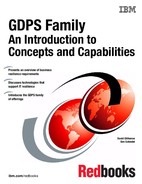
Figure 8-14 on page 239 shows a sample configuration consisting of the following components:
•A z/OS sysplex controlled by GDPS configured as a single-site workload (all application systems in Site1 in normal running mode) and the corresponding Metro Mirror configuration.
•A Linux cluster set (non-stretched cluster) with the active cluster in Site1 and a standby cluster in Site2. Data for the workload in the cluster set is mirrored using Metro Mirror under control by GDPS using the Open LUN support.
•An AIX stretched cluster with active-active application in both sites. Data replication is performed through LVM.

Figure 8-14 Sample GDPS/PPRC DCM configuration
The DDR feature that includes the GDPS agent communicates with the GDPS K-sys through communication links as shown in Figure 8-14.
Figure 8-15 on page 240 represents a failure scenario in which one or more failures occur in Site1, which can include a Metro Mirror mirroring failure, the loss of one or more production z/OS systems, or the loss of one or more SA AppMan clusters in Site1. A disaster is declared that includes the decision to recover all processing in Site2.
With GDPS DCM support providing the ability to manage SA AppMan clusters from GDPS, you have the ability to switch z/OS systems and data and SA AppMan systems and data to Site2 in a coordinated manner.
Figure 8-15 Sample GDPS/PPRC DCM configuration - Site1 failure
An existing GDPS script that previously performed failover and restart of System z resources can be extended to also include statements to automate the failover of SA AppMan clusters to Site2. When the additional script statements are executed as part of the site takeover script, GDPS automation performs the following actions to move System z resources from Site1 to Site2:
•It resets production systems in Site1.
•It reconfigures the secondary disks.
•It activates CBU for servers in Site2.
•It switches couple data sets to those in Site2.
•It activates partitions in Site2.
•It reIPLs P1, P2, and P3 in Site2.
GDPS performs the following actions to move the non-stretched SA AppMan Linux cluster from Site1 to Site2:
•It makes available those Metro Mirror secondary devices in Site2 (managed by Open LUN) that are associated with the Linux cluster.
•It sends a Reset Site1 command to SA AppMan to power off all distributed production systems in Site1.
•It sends a command to SA AppMan to start workload associated with the Linux cluster in Site2.
The AIX active-active stretched cluster managed by its automation product (for example HACMP) might have had production workload running in Site2 all along. If the production workload was not already running in Site2 at the time of the failure, the GDPS script statement to start workload in Site2 will see to it that the AIX workload is started.
This example demonstrates the coordinated recovery that can be accomplished across both the System z resources and the AppMan clusters, when there is an unplanned outage that affects Site1.
Integrated configuration of GDPS/GM and SA AppMan
The concepts and capabilities provided by Distributed Cluster Management (DCM) in conjunction with SA AppMan in a GDPS/GM environment are similar to those described in “Integrated configuration of GDPS/PPRC and SA AppMan” on page 235. In this section, we do not repeat the same concepts. Instead we provide an overview of the solution and explain the differences with the GDPS/PPRC implementation.
The major difference between the GDPS/PPRC and GDPS/GM implementations stems from the difference between these two solution models.
•GDPS/PPRC is a high availability and disaster recovery solution implemented across two sites separated by relatively short distance.
•GDPS/GM, due to the asynchronous nature of the copy technology and the typical distances between the two sites, is a disaster recovery-only solution.
This difference reflects on the DCM AppMan implementation. Whereas it might be possible to support stretched clusters in a GDPS/PPRC environment, stretch clusters do not make sense in a “failover” recovery model. Similarly, in a GDPS/PPRC environment, it is possible to use LVM instead of PPRC for replication. In a GDPS/GM environment, it is unlikely that LVM can be supported over large distances1.

Figure 8-16 SA Application Manager - Distributed Disaster Recovery configuration for GDPS/GM
Figure 8-16 provides a high-level depiction of how GDPS/GM and DCM AppMan integrate. Following is a list of the general characteristics of GDPS/GM DCM AppMan.
•The AppMan server runs on Linux for System z (guest or native).
•The AppMan server communicates with the GDPS/GM Remote Controlling system.
The AppMan server and the GDPS/GM Remote Controlling system are expected to be co-located in the Recovery site, although this is not mandatory.
•The Appman server and the clusters in the Application site that it manages can be separated by unlimited distances.
•The clusters in the Application Site are running business-critical workloads. The clusters in the recovery site can be standby or running discretionary workloads.
•GDPS manages Global Mirror replication on behalf of the AppMan clusters.
– Distributed data for one or more AppMan clusters can be in the same Global Mirror session together with the data for one or more System z systems if cross-system consistency is required. In this case, the System z systems and distributed clusters having their data mirrored in the same session are recovered together.
– Distributed data for different clusters can be managed as one or more independent Global Mirror sessions isolated from System z data. A Global Mirror session and the clusters having their data mirrored in that session will be the scope of recovery.
•If a recovery action is initiated, GDPS automation performs the Global Mirror data recovery and coordinates, with the AppMan server, the recovery actions for the distributed clusters. GDPS instructs the AppMan server to kill any discretionary workload on clusters that will be used to house critical workloads, and to start the critical workloads in the recovery site. All of this is accomplished with a single GDPS automation script.
8.3.4 Summary
The Distributed Cluster Management function of GDPS can provide a single point of control to monitor and manage both System z resources and distributed server resources. DCM can also provide coordinated failover for planned and unplanned events that can affect either the System z resources or the distributed server resources or both. In short, you can attain business resiliency across your entire enterprise.
1 Consult with your vendor to understand their support position.
..................Content has been hidden....................
You can't read the all page of ebook, please click here login for view all page.