

Infrastructure planning for availability and GDPS
In this chapter, we discuss a number of technologies that are available to help you achieve your goals related to IT resilience, recovery time, and recovery point objectives. To understand how the GDPS offerings described in this document can help you, it is important to have at least conceptual knowledge of the functions, capabilities, and limitations of these underlying technologies.
2.1 Parallel Sysplex overview
As discussed in Chapter 1, “Introduction to business resilience and the role of GDPS” on page 1, IT Resilience covers more than just recovery from a disaster. It also encompasses ensuring high availability on a day-to-day basis, protecting your applications from normal planned and unplanned outages. You cannot expect to be able to provide continuous or near-continuous application availability across a disaster if you are unable to provide that in normal operations.
Parallel Sysplex is the primary mechanism used by IBM to provide the highest levels of application availability on the System z1 platform. The logical first step in a business resiliency project is to do all you can to deliver the highest levels of service from your existing configuration. Implementing Parallel Sysplex with data sharing and dynamic workload routing not only provides higher levels of availability now, it also provides a foundation to achieve greater resiliency should you implement GDPS too.
In the following sections we briefly discuss Parallel Sysplex, the benefits you can derive by exploiting the technology, and the points to consider if you decide to implement GDPS/PPRC or GDPS/Active-Active. Because GDPS/XRC and GDPS/Global Mirror do not have a continuous availability (CA) aspect, there are no Parallel Sysplex considerations specifically relating to GDPS/XRC and GDPS/Global Mirror.
2.1.1 Maximizing application availability
There is only one way to protect applications from the loss of a single component (such as an IBM CICS® region or a z/OS system) and that is to run multiple, failure-isolated copies. This infers an ability to share data at the record level, with integrity, and to dynamically route incoming work requests across the available servers. Parallel Sysplex uses hardware and software components to link individual systems together in a cluster. Because all systems in the sysplex are able to share the same resources and data, they appear as a single image to applications and users, while at the same time providing the ability to eliminate single points of failure.
Having more than one instance of an application within the sysplex can shield your users from both planned and unplanned outages. With Parallel Sysplex, parts of the cluster can be brought down for maintenance, upgrades, or any other type of outage, while the applications continue to be available on other members of the sysplex.
GDPS/Active-Active further extends this concept with the ability to switch the workload between two sysplexes separated by virtually unlimited distance for both planned and unplanned outage situations.
Although it is not necessary to have a Parallel Sysplex before implementing most GDPS solutions, it is important to understand the role that Parallel Sysplex plays in supporting the continuous availability aspect of IT resilience. Technical information about implementing and exploiting Parallel Sysplex is available in other IBM documentation and is not covered in this document.
2.1.2 Multisite sysplex considerations
The considerations for a multisite sysplex depend on whether you plan to run production systems in both sites at the same time, or if all the production systems will be in a single site at any one time. Configurations where production systems can run in both sites at the same time are referred to as multisite workload configurations. Configurations where the production systems run together in one site or the other (but not split across multiple sites) are referred to as single-site workload configurations or sometimes as “active/standby” configurations. Other variations on this, where production systems are predominantly running at one site, but where partially active systems or systems only enabled for queries are running at the other site, are still considered multisite workloads.
|
Terminology note: This section is focused on a multisite sysplex, which is a single sysplex spread across multiple (typically two) sites, and how the workload is configured to run in those sites to provide near-continuous availability and metro distance DR.
Do not confuse it with the GDPS/Active-Active solution that uses some of the same terminology, but is related to multiple sysplexes (limited to two, currently) and how the workload is configured between the two sysplexes, not within any single sysplex.
In a GDPS/Active-Active environment, it is anticipated that each of the participating sysplexes will themselves be in an Active/Active configuration, providing local continuous availability with GDPS/PPRC and GDPS/Active-Active providing a solution for unlimited distance CA/DR. For more details about the GDPS/Active-Active solution, refer to Chapter 7, “GDPS/Active-Active” on page 173.
|
Several phrases are often used to describe variations of multisite workload. Brief definitions are included here for the more commonly implemented variations.
Active/Active This refers to a multisite workload configuration where z/OS systems are actively running in the same sysplex with active subsystems in more than one site at the same time. Typically this term also implies that applications take advantage of data sharing and dynamic workload routing in such a way that applications can freely move from one site to another. Finally, critical Parallel Sysplex resources are duplexed or replicated in such a way that if one site fails, the remaining site can recover workload within minutes after contending locks and communications timeouts clear. When combined with HyperSwap, an Active/Active configuration has the potential to provide near-continuous availability for applications even in the case of a site outage.
Active/Warm This refers to a multisite workload configuration that is similar to the Active/Active configuration, with production systems running at more than one site. The difference is that workload generally runs in one site at a time, with the systems in the other site simply IPLed without subsystems or other resources active.
This configuration is intended to save IPL time when moving workload between sites. It can be most effective for supporting the planned movement of workload because in many unplanned scenarios, the “warm” systems might also not survive.
Active/Query This refers to a multisite workload configuration that is quite close to the Active/Active configuration, but where workload at the second site is partitioned or restricted (possibly to queries only) in such a way as to limit impacts due to serialization, thereby protecting shared resources when delays due to distance between the sites is a concern. Again, depending on the configuration of the Coupling Facility structures (that is, whether they are duplexed across sites or basically in one site at a time), this configuration might only provide value for planned scenarios because in many unplanned scenarios the “query” or “hot standby” subsystems might not survive.
There are potentially many more configuration variations that you can come up with, but from a Parallel Sysplex and GDPS2 perspective, all of these fall into either the single-site or the multisite workload category.
Single-site or multisite workload configuration
When first introduced, Parallel Sysplexes were typically contained within a single site. Extending the distance between the operating system images and the Coupling Facility has an impact on the response time of requests using that Coupling Facility. Also, even if the systems sharing the data are spread across more than one site, all the primary disk subsystems would normally be contained in the same site, so a failure affecting the primary disks would impact the systems in both sites. As a result, a multisite workload configuration does not, in itself, provide significantly greater availability than a single-site workload configuration during unplanned outages. To achieve the optimal benefit from a multisite workload configuration for planned outages, HyperSwap should be used - this enables you to move applications and their data from one site to the other nondisruptively.
More specifically, be careful when planning a multisite workload configuration if the underlying Parallel Sysplex cannot be configured to spread the important Coupling Facility structures across the sites while still achieving the required performance. As discussed later in this chapter and illustrated in Table 2-1 on page 44, the Coupling Link technology can support links upwards of 100 km with qualified DWDMs. However, this does not mean that your workload will tolerate even 1 km of distance between the z/OS images and the CF. Individual coupling operations will be delayed by ten microseconds per kilometer. Although this time can be calculated, there is no safe way to predict the increased queuing effects caused by the increased response times and the degree of sharing that is unique to each environment. In other words, you will need to actually run your workload with connections at distance to evaluate the tolerance and impacts of distance.
Finally, the benefits of a multisite workload come with additional complexity. This must be taken into account when weighing the benefits of such configurations.
CF Structure Duplexing
There are two mechanisms for duplexing CF structures. The first of these, User-Managed Structure Duplexing, is only supported for use with DB2 Group Buffer Pool (GBP) structures. Duplexing the GBP structures can significantly reduce the time to recover the structures following a CF or CF connectivity failure. The performance impact of duplexing the GBP structures is small. Therefore, it is best to duplex the GBP structures used by a production DB2 data sharing group.
The other type of structure duplexing, System-Managed Coupling Facility Structure Duplexing (hereafter referred to as SM Duplexing), provides a general purpose, hardware-assisted and easy-to-exploit mechanism for duplexing CF structures. This feature is primarily intended to allow installations to do data sharing without having to have a failure-isolated CF. However, the design of SM Duplexing means that having the CFs a significant distance (kilometers) apart can have a dramatic impact on CF response times for the duplexed structures, and thus your applications, and needs careful planning and testing.
In addition to the response time question, there is another consideration relating to the use of cross-site SM Duplexing. Because communication between the CFs is independent of the communication between mirrored disk subsystems, a failure that results in remote copy being suspended would not necessarily result in duplexing being suspended at the same instant. In case of a potential disaster, you want the data in the “remote” CF to be frozen in time at the same instant the “remote” disks are frozen, so you can restart your applications from the moment of failure.
If you are using duplexed structures, it might seem that you are guaranteed to be able to use the duplexed instance of your structures if you have to recover and restart your workload with the frozen secondary copy of your disks. However, this is not always the case. There can be rolling disaster scenarios where prior to, following, or during the freeze event, an interruption occurs (perhaps failure of CF duplexing links) that forces CFRM to drop out of duplexing. There is no guarantee that the structure instance in the surviving site is the one that will be kept. It is possible that CFRM keeps the instance in the site that is about to totally fail. In this case, there will not be an instance of the structure in the site that survives the failure.
Furthermore, during a rolling disaster event, if you freeze secondary disks at a certain point but continue to update the primary disks and the CF structures, then the CF structures, whether duplexed or not, will not be usable if it is necessary to recover on the frozen secondary disks. This will depend on some of your installation’s policies.
To summarize, if there is a surviving, accessible instance of application-related structures, this might or might be consistent with the frozen secondary disks and therefore might or might not be usable. Furthermore, depending on the circumstances of the failure, even with structures duplexed across two sites you are not 100% guaranteed to have a surviving, accessible instance of the application structures. Therefore, you must have procedures in place to restart your workloads without the structure contents.
For more information, refer to the white paper entitled System-Managed CF Structure Duplexing, GM13-0103, available on the Internet at:
2.2 Data consistency
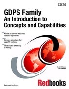
In an unplanned outage or disaster situation the ability to perform a database restart, rather than a database recovery, is essential to meet the Recovery Time Objective (RTO) of many businesses, which typically is less than an hour. Database restart allows starting a database application (as you would following a database manager abend or system abend) without having to restore it from backups. Database recovery is normally a process measured in many hours (especially if you have hundreds or thousands of databases to recover), and it involves restoring the last set of image copies and applying log changes to bring the databases up to the point of failure.
But there is more to consider than simply the data for one data manager. What if you have an application that updates data in IMS, DB2, and VSAM? If you need to do a recover for these, will your recovery tools not only allow you to recover them to the same point in time, but also to the level of granularity that ensures that either all or none of the updates made by one transaction are recovered? Being able to do a restart rather than a recover avoids these issues.
Data consistency across all copies of replicated data, spread across any number of storage subsystems and in some cases across multiple sites, is essential to providing not only data integrity but also the ability to perform a normal database restart in the event of a disaster.
2.2.1 Dependent write logic
Database applications commonly ensure the consistency of their data by using dependent write logic irrespective of whether data replication techniques are being used. Dependent write logic states that if I/O B must logically follow I/O A, then B will not be started until A completes successfully. This logic would normally be included in all software to manage data consistency. There are numerous instances within the software subsystem itself, such as databases, catalog/VTOC, and VSAM file updates, where dependent writes are issued.
As an example, in Figure 2-1, LOG-P is the disk subsystem containing the Database Management System (DBMS) logs, and DB-P is the disk subsystem containing the DBMS data segments. When the DBMS makes a database update it will (1) write an entry to the log indicating the update intent, (2) make the database update, and then (3) write another entry to the log indicating the update was made. If you are going to remote copy these volumes, it is vital that all the updates are mirrored to the secondary disks.
Figure 2-1 The need for data consistency
It is unlikely that all the components in a data center will fail at the same instant, even in the rare case of a full data center outage. The networks might fail first, or possibly one disk subsystem, or any other component in unpredictable combinations. No matter what happens, the remote image of the data must be managed such that cross-volume and subsystem data consistency is preserved during intermittent and staged failures that might occur over many seconds, even minutes. Such a staged failure is generally referred to as a “rolling disaster.”
Data consistency during a rolling disaster is difficult to achieve for synchronous forms of remote copy because synchronous remote copy is entirely implemented within disk subsystem pairs.
For example, in Figure 2-1 the synchronously mirrored data sets are spread across multiple disk subsystems for optimal performance. The volume containing the DBMS log on the LOG-P disk subsystem in Site1 is mirrored to the secondary volume in the LOG-S disk subsystem in Site2, and the volume containing the data segments in the DB-P disk subsystem in Site1 is mirrored to the secondary volume in the DB-S disk subsystem in Site2.
Assume that a disaster is in progress in Site1, causing the link between DB-P and DB-S to be lost before the link between LOG-P and LOG-S is lost. With the link between DB-P and DB-S lost, a write sequence of (1), (2), and (3) might be completed on the primary devices (depending on how the remote copy pair was defined) and the LOG writes (1) and (3) would be mirrored to the LOG-S device, but the DB write (2) would not have been mirrored to DB-S. A subsequent DBMS restart using the secondary copy of data in Site2 would clean up in-flight transactions and resolve in-doubt transactions, but the missing DB write (2) would not be detected. In this example of the missing DB write the DBMS integrity was compromised.3
We discuss data consistency for synchronous remote copy in more detail in “PPRC data consistency” on page 24.
For the two IBM asynchronous remote copy offerings, the consistency of the volumes in the recovery site is guaranteed because of the way these offerings work. This is discussed further in 2.4.3, “Global Mirror” on page 31 and “XRC data consistency” on page 27.
For GDPS/Active-Active, which relies on asynchronous software replication as opposed to the use of PPRC, XRC, or Global Mirror, consistency is managed within the replication software products discussed further in 2.4.5, “IBM software replication products” on page 35.
2.3 Synchronous versus asynchronous data transfer
Synchronous data transfer and asynchronous data transfer are two methods used to replicate data. Before selecting a data replication technology, you must understand the differences between the methods used and the business impact.
|
Terminology note: In this book we will continue to use the term Peer-to-Peer Remote Copy (PPRC) when referring to the synchronous disk replication architecture. The rebranded name of the IBM implementation of this architecture is IBM Metro Mirror, which will be used when specifically referring to the IBM implementation on the IBM Enterprise Storage Server (ESS) and the IBM DS8000 family of products.
Similarly, we will continue to use the term eXtended Remote Copy (XRC) when referring to the asynchronous disk copy technology that leverages the z/OS System Data Mover (SDM). The rebranded name of the IBM disk storage implementation is z/OS Global Mirror, which will be used specifically when referring to the IBM implementation on the IBM Enterprise Storage Server (ESS) and the IBM DS8000 family of products.
|
When using synchronous data transfer, illustrated in Figure 2-2 on page 20 using PPRC, the application writes are first written to the primary disk subsystem (1) and then forwarded on to the secondary disk subsystem (2). When the data has been committed to both the primary and secondary disks (3), an acknowledgement that the write is complete (4) is sent to the application. Because the application must wait until it receives the acknowledgement before executing its next task, there will be a slight performance impact. Furthermore, as the distance between the primary and secondary disk subsystems increases, the write I/O response time increases due to signal latency4.
The goals of synchronous replication are zero or near-zero loss of data, and quick recovery times from failures that occur at the primary site. Synchronous replication can be costly because it requires high-bandwidth connectivity.
One other characteristic of synchronous replication is that it is an enabler for nondisruptive switching between the two copies of the data that are known to be identical.

Figure 2-2 Synchronous versus asynchronous storage replication
With asynchronous replication, illustrated in Figure 2-2, with either z/OS Global Mirror (XRC) or with Global Mirror, the application writes to the primary disk subsystem (1) and receives an acknowledgement that the I/O is complete as soon as the write is committed on the primary disk (2). The write to the secondary disk subsystem is completed in the background. Because applications do not have to wait for the completion of the I/O to the secondary device, asynchronous solutions can be used at virtually unlimited distances with negligible impact to application performance. In addition, asynchronous solutions do not require as much bandwidth as the synchronous solutions.
With software-based asynchronous replication, as used in a GDPS/Active-Active environment, the process is somewhat similar to that described for XRC. Data is captured from the database subsystem logs at the source copy when a transaction commits data to the database. That captured data is then sent asynchronously to a second location where it is applied to the target copy of the database in near real time.
When selecting a data replication solution, perform a business impact analysis to determine which solution will meet the businesses requirements while ensuring your service delivery objectives continue to be met; see Figure 2-3. The maximum amount of transaction loss that is acceptable to the business (RPO) is one measurement used to determine which remote copy technology should be deployed. If the business is able to tolerate loss of committed transactions, then an asynchronous solution will likely provide the most cost-effective solution. When no loss of committed transactions is the objective, then synchronous remote copy must be deployed. In this case the distance between the primary and secondary remote copy disk subsystems, and the application’s ability to tolerate the increased response times, must be factored into the decision process.
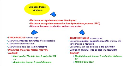
Figure 2-3 Business impact analysis
Many enterprises have both business and regulatory requirements to provide near-continuous data availability, without loss of transactional data, while protecting critical business data in the event of a wide-scale disruption. This can be achieved by implementing three-copy (sometimes referred to as three-site) mirroring solutions that exploit both synchronous and asynchronous replication technologies. Synchronous solutions are used to protect against the day-to-day disruptions with no loss of transactional data. Asynchronous replication is used to provide out-of-region data protection, with some loss of committed data, for wide-spread disruptions. The key is to ensure cross-disk subsystem data integrity and data consistency is maintained through any type of disruption.
For additional information about three-copy replication solutions see Chapter 9, “Combining Local/Metro continuous availability with out-of-region disaster recovery” on page 245.
2.4 Data replication technologies
There are two primary ways to make your data available following a disaster:
•By using a form of tape-based backup
•By using data replication to a recovery site (also known as remote copy)
This can be hardware-based or software-based replication.
For companies with an RTO of a small number of hours or less, a tape-based solution is unlikely to be acceptable, because it is simply not possible to restore all your volumes and apply all database logs in the time available. Therefore, we are assuming that if you are reading this document you already have, or are planning to implement, some form of data replication technology.
Remotely copying your data not only eliminates the time that would be required to restore the data from tape, it also addresses the problem of having to recover data that is generated between the last backup of an application system and the time when the application system fails. Depending on the technology used, remote copy implementations provide a real-time (or near-real-time) continuing copy of data between a source and a target.
IBM offers three basic technologies to provide this type of mirroring for disk storage:
•PPRC: Updates to the primary volumes are synchronously mirrored to the remote volumes and all interactions related to this activity are carried out between the disk subsystems.
•XRC: The task of retrieving the updates from the primary disk subsystem and applying those changes to the secondary volumes is carried out by a z/OS component called the System Data Mover (SDM).
•Global Mirror: This offering mirrors the data asynchronously. However, unlike XRC, all interactions are carried out between the disk subsystems rather than by an SDM.
These technologies are described more fully in the following sections. For an even more detailed explanation of the remote copy technologies described in the following sections, see the IBM Redbooks document IBM System Storage DS8000: Copy Services with IBM System z, SG24-6787.
IBM also offers a number of software-based replication products. Unlike the technologies listed for mirroring disk storage (which are application independent), most software replication products are specific to the database source and target in use. The following products are currently supported in a GDPS/Active-Active environment for replication of IMS and VSAM and DB2 data respectively:
•IBM InfoSphere® Data Replication for IMS for z/OS
•IBM InfoSphere Data Replication for VSAM for z/OS
•IBM InfoSphere Data Replication for DB2 for z/OS
These products are introduced in the following sections and more information can be found in the IBM Information Management Software for z/OS Solutions Information Center.
2.4.1 PPRC (IBM Metro Mirror)
PPRC ensures that after the volume pair has been established and remains synchronized that the secondary volume will always contain exactly the same data as the primary. The IBM implementation of PPRC, known as IBM Metro Mirror, provides synchronous data mirroring at distances up to 300 km (and potentially even greater distances, after technical review and approval).
|
Important: Always use caution when considering long distances. When we say that something is “supported up to xx km,” it means that the technology will work at that distance if you have qualified cross-site connectivity technology that supports that protocol. See 2.9, “Cross-site connectivity considerations” on page 42 for more details.
Additionally, you must consider the impact the increased response time will have on your applications. Some applications can tolerate the response time increase associated with cross-site distances of 100 km, but the same distance in another installation might make it impossible for the applications to deliver acceptable levels of performance.
So, carefully evaluate the projected response time impact, and apply that increase to your environment to see if the result is acceptable. Your vendor storage specialist can help you determine the disk response time impact of the proposed configuration.
|
Recovery Point Objective with PPRC
If you have a Recovery Point Objective of zero (0), meaning zero data loss, PPRC is the only IBM remote copy option that can achieve that objective.
That is not to say that you will always have zero data loss if using PPRC. Zero data loss means that there will never be updates made to the primary disks that are not mirrored to the secondaries. The only way to ensure zero data loss is to immediately stop all update activity to the primary disks if the remote copy relationship ceases to exist (if you lose connectivity between the primary and secondary devices, for example).
Thus, choosing to have zero data loss really means that you must have automation in place that will stop all update activity in the appropriate circumstances. It also means that you accept the possibility that the systems can be stopped for a reason other than a real disaster; for example, if the failure was caused by a broken remote copy link rather than a fire in the computer room. Completely avoiding single points of failure in your remote copy configuration, however, can reduce the likelihood of such events to an acceptably low level.
Supported platforms with PPRC
PPRC replication is supported for any IBM or non-IBM disk subsystem that supports the PPRC architecture, specifically the FREEZE/RUN architecture. PPRC can mirror both Fixed Block Architecture (FBA or FB) devices typically used by System z and non-System z platforms, and CKD devices traditionally used by mainframe operating systems such as z/OS, IBM z/VM, and IBM z/VSE. Not all operating systems necessarily support an interface to control the remote copy function. However, the PPRC function can be controlled from a connected z/OS system if there are sufficient CKD formatted volumes defined in the storage subsystem (as described more fully in 3.1.3, “Protecting distributed (FBA) data” on page 62 for GDPS/PPRC and 4.1.2, “Protecting distributed (FBA) data” on page 105 for GDPS/PPRC HyperSwap Manager).
With current implementations of PPRC, the primary and secondary disk subsystems must be from the same vendor, although vendors (including IBM) often support PPRC mirroring between different disk subsystem models of their own product lines. This can help with migrations and technology upgrades.
Distance with PPRC
The maximum distance supported for IBM Metro Mirror is 300 km (without an RPQ). Note that typical GDPS/PPRC and GDPS/HyperSwap manager configurations are limited to distances less than this due to Coupling Link or timer configurations. See 2.9.3, “Coupling links” on page 44 for more details about the supported distances for these Parallel Sysplex connections. Additionally, you will need to contact other storage vendors (if required) to understand the maximum distances supported by their PPRC compatible mirroring implementations.
Performance with PPRC
As the distance between your primary and secondary disk subsystems increases, the time it takes for your data to travel between the subsystems also increases. This might have a performance impact on your applications because they cannot proceed until the write to the secondary device completes.
Be aware that as response times increase, link utilization also will increase. Depending on the type and number of PPRC links you configured, additional links and the use of Parallel Access Volumes (PAVs) might help to provide improved response times at longer distances.
Disk Magic, a tool available to your IBM storage specialist, can be used to predict the impact of various distances, link types, and link numbers for IBM disk implementation. We consider access to the information provided by such a tool essential to a GDPS project using PPRC.
PPRC connectivity
Connectivity between the primary and secondary disk subsystems can be provided by direct connections between the primary and secondary disk subsystems, by IBM FICON® switches, by DWDMs, and by channel extenders.
The type of intersite connection (dark fiber or telecommunications link) available determines the type of connectivity you use: telecommunication links can be used by channel extenders, and the other types of connectivity require dark fiber.
You can find information about connectivity options and considerations for System z in the latest version of IBM System z Connectivity Handbook, SG24-5444.
PPRC data consistency
When using PPRC, the following sequence of actions occurs when an update I/O is issued to a primary volume:
1. Write to the primary volume (disk subsystem cache and Non-Volatile Store (NVS)).
Your production system writes data to a primary volume and a cache hit occurs.
2. Write to the secondary (disk subsystems cache and NVS).
The primary disk subsystem’s microcode then sends the update to the secondary disk subsystem’s cache and NVS.
3. Signal write complete on the secondary.
The secondary disk subsystem signals write complete to the primary disk subsystem when the updated data is in its cache and NVS.
4. Post I/O complete.
When the primary disk subsystem receives the write complete from the secondary disk subsystem, it returns Device End (DE) status to your application program. At this point, the application program can continue its processing and move on to any dependent writes that might have been waiting for this one to complete.
However, PPRC on its own only provides this consistency for a single write. Guaranteeing consistency across multiple logical subsystems and even across multiple disk subsystems requires automation on top of the PPRC function itself. This is where GDPS comes in with Freeze automation, described more fully for GDPS/PPRC in 3.1.1, “Protecting data integrity and data availability with GDPS/PPRC” on page 52 and for GDPS/PPRC HyperSwap Manager in 4.1.1, “Protecting data integrity and data availability with GDPS/PPRC HM” on page 96.
PPRC transparent disk swap
Because under normal conditions, the primary and secondary disks are known to be identical, with PPRC it is possible to swap to using the secondary copy of the disks in a manner that is transparent to applications. This is not a simple task and it requires tight control and coordination to perform for many devices shared by multiple systems in a timely manner. GDPS/PPRC and GDPS/PPRC HyperSwap Manager automation, in conjunction with support provided in z/OS, z/VM, and specific distributions of SUSE Linux for System z, provide such a transparent swap capability and it is known as HyperSwap.
HyperSwap is a key availability-enabling technology. For further details about GDPS HyperSwap, refer to “GDPS HyperSwap function” on page 56 for GDPS/PPRC and “GDPS HyperSwap function” on page 100.
Addressing z/OS device limits in a GDPS/PPRC environment
As clients implement IT resiliency solutions that rely on multiple copies of data, more and more are finding that the z/OS limit of 64K (65,536) devices is limiting their ability to grow or even to take advantage of technologies like HyperSwap. Clients can consolidate data sets to fewer larger volumes, but even with that, there are times when this might not make operational sense for all types of data.
To this end, z/OS introduced the concept of an “alternate subchannel set,” which can include the definition for certain types of disk devices. An alternate subchannel set provides another set of 64K devices for the following device types:
•Parallel Access Volume (PAV) alias devices
•PPRC secondary devices (defined as 3390D)
•FlashCopy target devices
Including PAV alias devices in an alternate subchannel set is transparent to GDPS and is common practice for current GDPS/PPRC and GDPS/PPRC HyperSwap Manager environments.
Support is included in GDPS/PPRC and GDPS/PPRC HyperSwap Manager to allow definition of PPRC secondary devices in an alternate subchannel set. With this feature, GDPS can support PPRC configurations with nearly 64 K device pairs. Alternate subchannel set support requires the GDPS-managed systems to be running on IBM z9® or later.
There are limitations to keep in mind when considering the use of this feature, specifically:
Enhanced support is provided in with IBM zEnterprise® 196 or 114 servers at GA2 MCL level (or later) that allows the PPRC secondary copy of the IPL, IODF, and stand-alone dump devices for z/OS systems in the GDPS sysplex to also be defined in the alternate subsystem set (MSS1). With this support, a client can define all z/OS PPRCed devices belonging to the GDPS sysplex uniformly with their secondary in the alternate subchannel set. This removes the necessity to define IPL, IODF, and stand-alone dump devices differently in MSS0. The following limitations still apply:
•Linux on System z devices (as part of a GDPS xDR configuration).
•Fixed Block Architecture (FBA) open-LUN devices managed by GDPS (these devices are not defined in any z/OS systems and do not consume any UCBs, and therefore do not contribute to UCB constraints).
•FlashCopy target devices managed by GDPS.
Summary
PPRC synchronous mirroring gives you the ability to remote copy your data in real time, with the potential for no data loss at the recovery site. PPRC is your only choice if your RPO is zero. PPRC is the underlying remote copy capability that the GDPS/PPRC and GDPS/PPRC HyperSwap Manager offerings are built on.
2.4.2 XRC (z/OS Global Mirror)
The eXtended Remote Copy (XRC) solution consists of a combination of software and hardware functions. XRC maintains a copy of the data asynchronously at a remote location. It involves a System Data Mover (SDM) that is a component of the z/OS operating system working in conjunction with supporting microcode in the primary disk subsystems. The SDM(s) running in the remote location are channel-attached to the primary disk subsystems. They periodically pull the updates from the primary disks, sort them in time stamp order, and apply the updates to the secondary disks. This provides point-in-time consistency for the secondary disks. The IBM implementation of XRC is branded as z/OS Global Mirror. This name is used interchangeably with XRC in many places, including in this document.
Recovery Point Objective
Because XRC collects the updates from the primary disk subsystem some time after the I/O has completed, there will always be an amount of data that has not been collected when a disaster hits. As a result, XRC can only be used when your Recovery Point Objective is greater than zero (0). The amount of time that the secondary volumes lag behind the primary depends mainly on the following items:
•The performance of the SDM
The SDM is responsible for collecting, sorting, and applying all updates. If there is insufficient capacity (MIPS, storage, and I/O resources) available to the SDM, this will result in longer delays collecting the updates from the primary disk subsystems, causing the secondaries to drift further behind during peak times.
•The amount of bandwidth
If there is insufficient bandwidth to transmit the updates in a timely manner, contention on the remote copy links can cause the secondary volumes to drift further behind at peak times.
•The use of device blocking
Enabling blocking for devices will result in I/O write activity to be paused for devices with high update rates. This allows the SDM to offload the write I/Os from cache, resulting in a smaller RPO.
•The use of write pacing
Enabling write pacing for devices with high write rates will result in delays being inserted into the application’s I/O response to prevent the secondary disk from falling behind. This option will slow the I/O activity, resulting in a smaller RPO; it is less disruptive than device blocking.
Because XRC is able to pace the production writes, it is possible to provide an average RPO of 1 to 5 seconds and maintain a guaranteed maximum RPO, if sufficient bandwidth and resources are available. However, it is possible that the mirror will suspend, or that production workloads will be impacted, if the capability of the replication environment is exceeded due to either of the following reasons:
•Unexpected peaks in the workload
•An underconfigured environment
To minimize the lag between the primary and secondary devices, you must have sufficient connectivity and a well-configured SDM environment. For more information about planning for the performance aspects of your XRC configuration, see the chapter about capacity planning in DFSMS Extended Remote Copy Installation Planning Guide, GC35-0481.
Supported platforms
There are two aspects to “support” for XRC. The first aspect is the ability to append a time stamp to all write I/Os so the update can subsequently be remote copied by an SDM. This capability is provided in the following operating systems:
•Any supported release of z/OS
•Linux for System z when using CKD format disks
•z/VM with STP and appropriate updates (contact IBM support for the most current details)
|
Note: XRC does not support FBA devices.
|
It is also possible to use XRC to remote copy volumes being used by System z operating systems that do not time stamp their I/Os. However, in this case, it is not possible to provide consistency across multiple LSSs. The devices must all be in the same LSS to provide consistency. For more information, refer to the section about understanding the importance of timestamped writes in the latest revision of z/OS DFSMS Advanced Copy Services, SC35-0428.
The other aspect is which systems can run the System Data Mover function. In this case, the only system that supports this is any supported release of z/OS.
Distance and performance
Because XRC is an asynchronous remote copy capability, the amount of time it takes to mirror the update to the remote disks does not impact the response times to the primary volumes. As a result, virtually unlimited distances between the primary and secondary disk subsystems are supported, with minimal impact to the response time of the primary devices.
Connectivity
If the recovery site is within the distance supported by a direct FICON connection, switches/directors, or DWDM, then you can use one of these methods to connect the SDM system to the primary disk subsystem. Otherwise, you have to use channel extenders and telecommunication lines.
XRC data consistency
XRC uses time stamps and consistency groups to ensure your data is consistent across the copy operation. When an XRC pair is established, the primary disk subsystem notifies all systems with a logical path group for that device, and the host system DFSMSdfp software starts to time stamp all write I/Os to the primary volumes. This is necessary to provide data consistency.
XRC is implemented in a cooperative way between the disk subsystems in the primary site and the SDMs, which typically are in the recovery site. A brief outline of the data flow follows (see Figure 2-4):
1. The primary system writes to the primary volumes.
2. Primary disk subsystem posts I/O complete.
Your application I/O is signalled completed when the data is written to the primary disk subsystem's cache and NVS. Channel End (CE) and Device End (DE) are returned to the writing application. These signal that the updates have completed successfully. A time stamped copy of the update is kept in the primary disk subsystems cache. Dependent writes can proceed at this point.

Figure 2-4 Data flow when using z/OS Global Mirror
3. Offload data from primary disk subsystem to SDM.
Every so often (several times a second), the SDM requests each of the primary disk subsystems to send any updates that have been received. The updates are grouped into record sets, which are asynchronously offloaded from the cache to the SDM system.
Within the SDM, the record sets, perhaps from multiple primary disk subsystems, are processed into consistency groups (CGs) by the SDM. The CG contains records that have their order of update preserved across multiple disk subsystems participating in the same XRC session. This preservation of order is vital for dependent write I/Os such as databases and logs. The creation of CGs guarantees that XRC will apply the updates to the secondary volumes with update sequence integrity for any type of data.
4. Write to secondary.
When a CG is formed, it is written from the SDM’s buffers to the SDM’s journal data sets. Immediately after the CG has been hardened on the journal data sets, the records are written to their corresponding secondary volumes. Those records are also written from the SDM’s buffers.
5. The XRC control data set is updated to reflect that the records in the CG have been written to the secondary volumes.
Coupled Extended Remote Copy
XRC is an effective solution for mirroring many thousands of volumes. However, a single SDM instance can only manage replication for a finite number of devices. You can use the Coupled XRC (CXRC) support to extend the number of devices for added scalability.
CXRC provides the ability to couple multiple SDMs running in the same or different LPARs together into a master session. CXRC coordinates the consistency of data across coupled sessions in a master session, allowing recovery of data for all the volumes in the coupled sessions to a consistent time.
If the sessions are not coupled, recoverable consistency is provided only within each individual SDM, not across SDMs. All logically related data (for example, all the data used by a single sysplex) should be copied by one SDM, or a single group of coupled SDMs.
Multiple Extended Remote Copy
In addition to the additional capacity enabled by Coupled XRC, there is also an option called Multiple XRC (MXRC). MXRC allows you to have up to 20 SDMs in a single LPAR, of which 13 can be coupled together into a cluster. These can then be coupled to SDMs or clusters running in other LPARs through CXRC. Up to 14 SDM clusters can then be coupled together, allowing for an architectural limit of coupled consistency across 182 SDMs.
Multiple Reader
XRC Multiple Reader (also known as Extended Reader) allows automatic load balancing over multiple readers in an XRC environment. A reader is a task that is responsible for reading updates from a primary LSS. Depending on the update rate for the disks in an LSS, a reader task might not be able to keep up with pulling these updates and XRC could fall behind. The function can provide increased parallelism through multiple SDM readers and improved throughput for XRC remote mirroring configurations.
It can allow XRC to:
•Better sustain peak workloads for a given bandwidth
•Increase data currency over long distances
•Replicate more capacity while maintaining the same recovery point objective
•Help avoid potential slowdowns or suspends caused by I/Os that are not being processed fast enough
Prior to the introduction of Multiple Readers, you needed to plan carefully to balance the primary volume update rate versus the rate that the SDM could “drain” the data. If the drain rate was unable to keep up with the update rate, there was a potential to impact application I/O performance.
GDPS/XRC can exploit this multireader function, and thus provide these benefits.
Extended Distance FICON
Extended Distance FICON is an improvement focused on providing XRC clients a choice of selecting less complex channel extenders built on frame forwarding technology rather than channel extenders that need to emulate XRC read commands to optimize the channel transfer through the channel extender to get the best performance.
Extended distance FICON enables mirroring over longer distances without substantial reduction of effective data rate. It can significantly reduce the cost of remote mirroring over FICON for XRC.
Extended Distance FICON is supported only on the IBM system z10™ and later servers, and the IBM System Storage DS8000 disk subsystems.
SDM Offload to zIIP
The System Data Mover (SDM) is allowed to run on one of the specialty engines referred to as a System z Integrated Information Processor (zIIP) offered on IBM System z9® and later processors. By offloading some of the SDM workload to a zIIP, better price performance and improved utilization of resources at the mirrored site can be achieved.
One benefit is that DFSMS SDM processing is redirected to a zIIP processor, which can lower server utilization at the mirrored site. Another benefit is that with an investment of a zIIP specialty processor at the mirrored site, you might now be able to cost justify the investment in and implementation of a disaster recovery solution that can lower server utilization at the mirrored site, while at the same time reduce software and hardware fees.
Scalability in a GDPS/XRC environment
As clients implement IT resiliency solutions that rely on multiple copies of data, more and more are finding that the z/OS limit of 64 K (65,536) devices is limiting their ability to grow. Clients can consolidate data sets to fewer larger volumes, but even with that, there are times when this might not make operational sense for all types of data.
In an XRC replication environment, the SDM system or systems are responsible for performing replication. An SDM system will need to address a small number of XRC infrastructure volumes plus the primary and secondary XRC devices that it is responsible for and possibly the FlashCopy target devices. This means, assuming target FlashCopy devices are also defined to the SDM system, that each SDM system can manage XRC replication for up to roughly 21 K primary devices. However, as described in “Multiple Extended Remote Copy” on page 29 and “Coupled Extended Remote Copy” on page 29, it is possible to run multiple clustered and coupled SDMs across multiple z/OS images. As you can see, you have more than ample scalability.
Furthermore, in a GDPS/XRC environment it is possible to use “no UCB” FlashCopy, in which case you do not need to define the FlashCopy target devices to the SDM systems. This further increases the number of devices each SDM system can handle.
Hardware prerequisites
XRC requires, on IBM disk subsystems, that primary IBM disk subsystems have the IBM z/OS Global Mirror feature code installed. It is not necessary for the primary and secondary disks to be the same device type, although they must both have the same geometry and the secondary device must be at least as large as the primary device.
XRC is also supported on disk subsystems from other vendors that have licensed and implemented the interfaces from IBM, and it is possible to run with a heterogeneous environment with multiple vendors’ disks. Target XRC volumes can also be from any vendor, even if the target subsystem does not support XRC, thus enabling investment protection.
|
Note: Keep in mind that at some point, you might have to remote copy from the recovery site back to the production site. GDPS/XRC defines procedures and provides specific facilities for switching your production workload between the two regions.
To reverse the XRC direction, the IBM z/OS Global Mirror feature code must also be installed in the secondary disk subsystems that will become primary when you reverse the replication direction. Additionally, to reverse the replication direction. the primary and secondary devices must be the same size.
In summary, it makes sense to maintain a symmetrical configuration across both primary and secondary devices.
|
An additional requirement is that all the systems writing to the primary volumes must be connected to the same timer network. It is not necessary for them all to be in the same sysplex, simply that they all share the same time source.
Summary
XRC provides a proven disk mirroring foundation for an enterprise disaster recovery solution that provides large scalability and good performance.
XRC is a recommended solution if your site has these requirements:
•Extended distances between primary and recovery site
•Consistent data, at all times, in the recovery site
•Ability to maintain the highest levels of performance on the primary system
•Can accept a small time gap between writes on the primary system and the subsequent mirroring of those updates on the recovery system
•Scale with performance to replicate a large number of devices with consistency.
•Run with a heterogeneous environment with multiple vendors’ disks.
2.4.3 Global Mirror
Global Mirror is an asynchronous remote copy technology that enables a two-site disaster recovery and backup solution for the System z and open systems environments. Using asynchronous technology, Global Mirror operates over Fibre Channel Protocol (FCP) communication links and is designed to maintain a consistent and restartable copy of data at a remote site that can be located at virtually unlimited distances from the local site.
Global Mirror works by using three sets of disks, as shown in Figure 2-5 on page 32. Global Copy (PPRC Extended Distance, or PPRC-XD), which is an asynchronous form of PPRC, is used to continually transmit data from the primary (A) to secondary (B) volumes, using the out-of-sync bitmap to determine what needs to be transmitted. Note that Global Copy does not guarantee that the arriving writes at the local site are applied to the remote site in the same sequence. Therefore, Global Copy by itself does not provide data consistency.
If there are multiple physical primary disk subsystems, one of them is designated as the Master and is responsible for coordinating the creation of consistency groups. The other disk subsystems are subordinates to this Master.
Each primary device maintains two bitmaps. One bitmap tracks incoming changes. The other bitmap tracks which data tracks must be sent to the secondary before a consistency group can be formed in the secondary.
Periodically, depending on how frequently you want to create consistency groups, the Master disk subsystem will signal the subordinates to pause application writes and swap the change recording bitmaps. This identifies the bitmap for the next consistency group. While the I/Os are paused in all LSSs in the Global Mirror session, any dependent writes will not be issued because the CE/DE has not been returned. This maintains consistency across disk subsystems. The design point to form consistency groups is 2-3 ms.
After the change recording bitmaps are swapped, write I/Os are resumed and the updates that remain on the Global Mirror primary for the current consistency group will be drained to the secondaries. After all of the primary devices have been drained, a FlashCopy command is sent to the Global Mirror secondaries (B), which are also the FlashCopy source volumes, to perform a FlashCopy to the associated FlashCopy target volumes (C). The tertiary or C copy is a consistent copy of the data. Remember the B volumes are secondaries to Global Copy and are not guaranteed to be consistent. The C copy provides a “golden copy” which can be used to make the B volumes consistent in case recovery is required. Immediately after the FlashCopy process is logically complete, the primary disk subsystems are notified to continue with the Global Copy process. For more information about FlashCopy, see 2.6, “FlashCopy” on page 37.
After Global Copy is resumed, the secondary or B volumes are inconsistent. However, if there is a need for recovery, the FlashCopy target volumes provide the consistent data for recovery.
All this processing is done under the control of microcode in the disk subsystems. You can have up to 17 mirrored pairs (one Master primary and secondary pair, and 16 Subordinate primary and secondary pairs) in a pool.

Figure 2-5 Global Mirror: How it works
Recovery Point Objective
Because Global Mirror is an asynchronous remote copy solution, there will always be an amount of data that will need to be recreated following a disaster. As a result, Global Mirror can only be used when your Recovery Point Objective (RPO) requirement is greater than zero (0). The amount of time that the FlashCopy target volumes lag behind the primary depends mainly on the following items:
•How often consistency groups are built
This is controlled by the installation and can be specified in terms of seconds.
•The amount of bandwidth
If there is insufficient bandwidth to transmit the updates in a timely manner, contention on the remote copy links can cause the secondary volumes to drift further behind at peak times. The more frequently you create consistency groups, the more bandwidth you will require.
Although it is not unusual to have an average RPO of five to ten seconds with Global Mirror, it is possible that the RPO will increase significantly if production write rates exceed the available resources. However, unlike z/OS Global Mirror, the mirroring session will not be suspended and the production workload will not be impacted if the capacity of the replication environment is exceeded due to unexpected peaks in the workload or an underconfigured environment.
To maintain a consistent lag between the primary and secondary disk subsystems, you must have sufficient connectivity. For more information about planning for the performance aspects of your Global Mirror configuration, see IBM System Storage DS8000: Copy Services with IBM System z, SG24-6787.
Supported platforms
The IBM ESS and DS8000 families of disk subsystems support Global Mirror. For other enterprise disk vendors, contact your vendor to determine whether they support Global Mirror and if so, on which models.
Distance and connectivity
Because Global Mirror is an asynchronous remote copy capability, the amount of time it takes to mirror the update to the remote disks does not impact the response times to the primary volumes. As a result, virtually unlimited distances between the primary and secondary disk subsystems are supported.
Global Mirror requires FCP links on the disk subsystems. If the recovery site is within the distance supported by FCP direct connect, switches, or DWDM, you can use one of those methods to connect the primary and secondary disk subsystems. Otherwise, you must use network extension technology that supports FCP links.
Addressing z/OS device limits in a GDPS/GM environment
As clients implement IT resiliency solutions that rely on multiple copies of data, more and more are finding that the z/OS limit of 64 K (65,536) devices is limiting their ability to grow. Clients can consolidate data sets to fewer larger volumes, but even with that, there are times when this might not make operational sense for all types of data.
To this end, z/OS introduced the concept of an “alternate subchannel set,” which can include the definition for certain types of disk devices. An alternate subchannel set provides another set of 64 K devices for the following device types:
•Parallel Access Volume (PAV) alias devices
•PPRC secondary devices (defined as 3390D)
•FlashCopy target devices
Including PAV alias devices in an alternate subchannel set is transparent to GDPS and is common practice for many client configurations.
The application site Controlling system requires access to the GM primary devices and can address up to 64K devices. The recovery site Controlling system requires access to both the GM secondary and the GM FlashCopy devices. GDPS supports defining the GM FlashCopy devices in an alternate subchannel set (MSS1). This allows 64K devices to be replicated in a GDPS/GM environment.
Summary
Global Mirror provides an asynchronous remote copy offering that supports virtually unlimited distance, without the requirement of an SDM system to move the data from primary to secondary volumes. Global Mirror also supports a wider variety of platforms because it supports FBA devices and removes the requirement for timestamped updates that is imposed by XRC.
Conversely, Global Mirror is currently not as scalable as XRC because it only supports a maximum of 17 storage subsystems. In addition, Global Mirror does not have the multiple vendor flexibility provided by XRC.
2.4.4 Combining disk remote copy technologies for CA and DR
In this section we briefly describe Metro/Global Mirror and Metro/z/OS Global Mirror. For more detailed information, refer to Chapter 9, “Combining Local/Metro continuous availability with out-of-region disaster recovery” on page 245. Combining the technologies of Metro Mirror and HyperSwap with either Global Mirror or XRC (also referred to as z/OS Global Mirror in this section) allows clients to meet requirements for continuous availability (CA) with zero data loss locally within metropolitan distances for most failures, along with providing a disaster recovery (DR) solution in the case of a region-wide disaster. This combination might also allow clients to meet increasing regulatory requirements.
Metro Global Mirror
Metro Global Mirror (MGM) is a cascading data replication solution that combines the capabilities of Metro Mirror and Global Mirror.
Synchronous replication between a primary and secondary disk subsystem located either within a single data center, or between two data centers located within metropolitan distances, is implemented using Metro Mirror. Global Mirror is used to asynchronously replicate data from the secondary disks to a third disk subsystem located in a recovery site typically out of the local metropolitan region. As described in 2.4.3, “Global Mirror” on page 31, a fourth set of disks, also located in the recovery site, are the FlashCopy targets used to provide the consistent data for disaster recovery. Because both Metro Mirror and Global Mirror are hardware-based remote copy technologies, CKD and FBA devices can be mirrored to the recovery site protecting both System z and open system data.
For enterprises that require consistency across both distributed systems and System z data, MGM provides a comprehensive three-copy data replication strategy to protect against day-to-day disruptions, while protecting critical business data and functions in the event of a wide-scale disruption.
Metro z/OS Global Mirror
GDPS Metro/z/OS Global Mirror (MzGM) is a multitarget data replication solution that combines the capabilities of Metro Mirror and XRC (z/OS Global Mirror).
Synchronous replication between a primary and secondary disk subsystem located either within a single data center, or between two data centers located within metropolitan distances, is implemented using Metro Mirror. XRC is used to asynchronously replicate data from the primary disks to a third disk system located in a recovery site, typically out of the local metropolitan region.
Because XRC only supports CKD devices, only System z data can be mirrored to the recovery site. However, because both PPRC and XRC are supported by multiple storage vendors, this solution provides flexibility that MGM cannot.
For enterprises looking to protect System z data, MzGM delivers a three-copy replication strategy to provide continuous availability for day-to-day disruptions, while protecting critical business data and functions in the event of a wide-scale disruption.
2.4.5 IBM software replication products
This section does not aim to provide a comprehensive list of all IBM software-based replication products, Instead, it provides an introduction to the supported products within the GDPS/Active-Active solution.
These are:
•InfoSphere Data Replication for IMS for z/OS
•InfoSphere Data Replication for VSAM for z/OS
•InfoSphere Data Replication for DB2 for z/OS
These products provide the capability to asynchronously copy changes to data held in IMS or DB2 databases or VSAM files from a source to target copy. Fine-grained controls allow you to precisely define what data is critical to your workload and needs to be copied in real time between the source and target. Unlike disk replication solutions that are application- or data-agnostic and work at the z/OS volume level, software replication does not provide a mechanism for copying all possible data types in your environment. As such, it is suited only to provide a CA/DR solution for specific workloads that can tolerate only the IMS, DB2 or VSAM database-resident information to be copied between locations. This is also discussed in Chapter 7, “GDPS/Active-Active” on page 173.
InfoSphere Data Replication for IMS for z/OS
IMS Replication provides the mechanisms for producing copies of your IMS databases and maintaining the currency of the data in near real time, typically between two systems separated by geographic distances. There is essentially no limit to the distance between source and target systems because the copy technique is asynchronous and uses TCP/IP as the protocol to transport the data over your wide area network (WAN).
IMS replication employs Classic data servers in the source and target systems to provide the replication services.
Classic source server
The Classic source server reads the IMS log data and packages changes to the specified databases into messages that are then sent through TCP/IP to the target location.
Classic target server
The Classic target server, running in the target location, receives messages from the source server and applies the changes to a replica of the source IMS database, in near real time.
IMS replication provides mechanisms to ensure that updates to a given record in the source database are applied in the same sequence in the target replica. Furthermore, IMS replication maintains a bookmark to know where it has reached in processing the IMS log data so that if any planned or unplanned outage occurs, it can later catch up knowing where it was at the time of the outage.
For more information about IMS replication, see the section on InfoSphere IMS Replication for z/OS V10.1 in the IBM Information Management Software for z/OS Solutions Information Center.
InfoSphere Data Replication for VSAM for z/OS
VSAM replication is very similar in structure to IMS replication. For CICS/VSAM workloads, the transaction data for selected VSAM data sets is captured using the CICS log streams as the source. For non-CICS workloads, CICS VSAM Recovery (CICS VR) logs are used as the source for capturing VSAM update information. The updates are transmitted to the target using TCP/IP, where they are applied to the target data sets upon receipt.
InfoSphere Data Replication for DB2 for z/OS
InfoSphere Replication Server for z/OS, as used in the GDPS/Active-Active solutions, is also known as Q replication. It provides a high capacity and low latency replication solution that uses IBM WebSphere® MQ message queues to transmit data updates between source and target tables of a DB2 database.
Q replication is split into two distinct pieces:
•Q capture program or engine
•Q apply program or engine
Q capture
The Q capture program reads the DB2 logs or changes to the source table or tables that you want to replicate. These changes are then put into MQ messages and sent across the MQ infrastructure to the system where the target table resides. There they are read and applied to the target table by the Q apply program.
The Q capture program is quite flexible in terms of what can be included or excluded from the data sent to the target and even the rate at which data is sent can be modified if required.
By the nature of the method of Q replication, the replication of data is an asynchronous process. Even so, an RPO of a few seconds is possible even in high update environments.
Q apply
The Q apply program takes MQ messages from a receive queue, or queues and then applies the changes held within the message to the target tables. The Q apply program is designed in such a way to use parallelism to keep up with updates to multiple targets while maintaining any referential integrity constraints between related target tables.
Both the Q capture and Q apply programs have mechanisms to track what has been read from the logs and sent to the target site, and what has been read from the receive queues and applied to the target tables, including any dependencies between updates. This in turn provides data consistency and allows for restart of both the capture and apply programs, if this is required or in case of failures.
For more information about Q replication, see the Replication and Event Publishing section of the IBM Information Management Software for z/OS Solutions Information Center.
2.5 Tape resident data
Operational data, that is, data that is used directly by applications supporting users, is normally found on disk. However, there is another category of data (called support data) that supports the operational data; this often resides in tape subsystems. Support data typically covers migrated data, point-in-time backups, archive data, and so on. For sustained operation in the failover site, the support data is indispensable. Furthermore, some enterprises have mission-critical data that only resides on tape. You need a solution to ensure that tape data is readily accessible at your recovery site.
Just as you mirror your disk-resident data to protect it, similarly you can mirror your tape-resident data. GDPS provides support for management of the IBM Virtualization Engine TS77005. Refer to 3.1.2, “Protecting tape data” on page 61 for details about GDPS TS7700 support.
The IBM Virtualization Engine TS7700 provides comprehensive support for replication of tape data. See IBM Virtualization Engine TS7700, SG24-7975 for more information about the TS7700 technology that complements GDPS for tape data.
2.6 FlashCopy
FlashCopy provides a point-in-time (PiT) copy of a volume, with almost instant availability for the user of both the source and target volumes. Additionally, there is a data set-level FlashCopy supported for z/OS volumes. Only a minimal interruption is required for the FlashCopy relationship to be established. The copy is then created under the covers by the disk subsystem, with minimal impact on other disk subsystem activities. The volumes created when you FlashCopy your secondary volumes are called tertiary volumes.
FlashCopy and disaster recovery
FlashCopy has specific benefits in relation to disaster recovery. For example, consider what happens if you temporarily lose connectivity between primary and secondary PPRC volumes. At the point of failure, the secondary volumes will be consistent. However, during the period when you are resynchronizing the primary and secondary volumes, the secondary volumes are inconsistent (because the updates are not applied in the same time sequence that they were written to the primaries). So, what happens if you have a disaster during this period? If it is a real disaster, your primary disk subsystem will be a smoldering lump of metal on the computer room floor. And your secondary volumes are inconsistent, so those volumes are of no use to you either.
So, how do you protect yourself from such a scenario? One way (our recommended way) is to take a FlashCopy of the secondary volumes just before you start the resynchronization process. This at least ensures that you have a consistent set of volumes in the recovery site. The data might be a number of hours behind the primary volumes, but even data a few hours old that is consistent is better than current, but unusable, data.
An additional benefit of FlashCopy is that it provides the ability to perform disaster recovery tests while still retaining disaster recovery readiness. The FlashCopy volumes you created when doing the resynchronization (or subsequently) can be used to enable frequent testing (thereby ensuring that your recovery procedures continue to be effective) without having to use the secondary volumes for that testing.
FlashCopy can operate in a number of different modes. GDPS uses one of the following modes of FlashCopy, depending on the GDPS offering:
COPY When the volumes are logically copied, the FlashCopy session continues as a background operation, physically copying all the data from the source volume to the target. When the volumes have been physically copied, the FlashCopy session ends. In this mode, the FlashCopy target physical volume will be a mirror image of the source volume at the time of the FlashCopy.
NOCOPY When the volumes are logically copied, a FlashCopy session continues as a background operation, physically copying only those tracks subsequently updated by write operations to the source volume. In this mode, the FlashCopy target physical volume only contains data that was changed on the source volume after the FlashCopy.
NOCOPY2COPY Change existing FlashCopy relationship from NOCOPY to COPY. This can be done dynamically. When one or more NOCOPY relationships exist for a source volume, NOCOPY2COPY will initiate a background copy for all target relationships with intersecting source extents from the point in time the NOCOPY was issued. Upon completion of the background copy, the converted relationship or relationships will be terminated.
INCREMENTAL This allows repetitive FlashCopies to be taken, but only the tracks that have changed since the last FlashCopy will be copied to the target volume. This provides the ability to refresh a FlashCopy relationship and bring the target up to the source’s newly established point-in-time. Incremental FlashCopy helps reduce the background copy completion time when only a subset of data on either the source or target has changed, thus giving you the option to perform a FlashCopy on a more frequent basis.
CONSISTENT This option is applicable to GDPS/PPRC and GDPS/HM environments. It creates a consistent set of tertiary disks without suspending the PPRC mirror. It uses the FlashCopy Freeze capability which, similar to PPRC Freeze, puts all source disks in Extended Long Busy to ensure that the FlashCopy source disks are consistent before the point-in-time copy is made. After the source disks are consistent, the FlashCopy is taken (quite fast) and the Freeze is thawed.
Without this support, to produce a consistent point-in-time copy of the secondary disks, you would need to suspend the PPRC mirror (planned freeze) and then resynchronize PPRC. HyperSwap would remain disabled from the time you suspended PPRC until the mirror is full duplex again; however, this can take a long time depending on how much data was updated while PPRC remained suspended. In comparison, with Consistent FlashCopy, HyperSwap is only disabled during the FlashCopy Freeze, which should be simply a few seconds.
GDPS gives you the capability to restrict the FlashCopy Freeze duration and to abort the FlashCopy operation if the FlashCopy Freeze time exceeds your threshold.
To create a consistent point-in-time copy of the primary disks without Consistent FlashCopy, you would need to somehow make sure that there is no I/O on the primary disks (effectively, you would need to stop the production systems). With Consistent FlashCopy, production systems continue to run and I/O is prevented during the few seconds until the FlashCopy Freeze completes. After the FlashCopy Freeze completes, the primary disks are in a consistent state, the FlashCopy operation itself is quite fast, and then the freeze is thawed and production systems resume I/O. Consistent FlashCopy can be used in conjunction with COPY, NOCOPY, or INCREMENTAL FlashCopy.
Zero Suspend This option is applicable to GDPS/XRC environments. It creates a recoverable set of tertiary disks for recovery testing with no suspension of the XRC operation. This allows DR testing to be performed without ever losing the DR capability. Before this support, to produce a consistent tertiary copy you needed to suspend XRC for all volumes, FlashCopy secondary volumes, and then resynchronize XRC sessions.
If you plan to use FlashCopy, remember that the source and target volumes must be within the same physical disk subsystem. This is a capacity planning consideration when configuring and planning for the growth of your disk subsystems.
Also remember that if you performed a site switch to run in the recovery site, at some point you will want to return to the production site. To provide equivalent protection and testing capability no matter which site you are running in, consider providing FlashCopy capacity in both sites.
Furthermore, note that GDPS does not perform FlashCopy for simply selected volumes. The GDPS exploitation of FlashCopy is for the purposes of protection during resynchronization and for testing. Both of these tasks require that a point-in-time copy for the entire configuration is made. GDPS FlashCopy support assumes that you will provide FlashCopy target devices for the entire configuration and that every time GDPS performs a FlashCopy, it will be for all secondary devices (GDPS/PPRC also supports FlashCopy for primary devices).
User-initiated FlashCopy
User-initiated FlashCopy supports FlashCopy of all defined FlashCopy volumes using panel commands, GDPS scripts, or GDPS NetView commands, depending on which GDPS product is used.
FlashCopy Space Efficient (FlashCopy SE)
FlashCopy SE is functionally not much different from the standard FlashCopy. The concept of space efficient with FlashCopy SE relates to the attributes or properties of a DS8000 volume. As such, a space efficient volume can be used like any other DS8000 volume. However, the intended and only recommended use is as a target volume in a FlashCopy relationship.
When a normal volume is created, it occupies the defined capacity on the physical drives. A space efficient volume does not occupy physical capacity when it is initially created. Space gets allocated when data is actually written to the volume. This allows the FlashCopy target volume capacity to be thinly provisioned (that is, smaller than the full capacity of the source volume). In essence this means that when planning for FlashCopy, you may provision less disk capacity when using FlashCopy SE than when using standard FlashCopy, which can help lower the amount of physical storage needed by many installations
All GDPS products support FlashCopy SE. Details of how FlashCopy SE is used by each offering is discussed in the specific chapter relating to that offering.
2.7 Automation
If you have challenging recovery time and recovery point objectives, implementing disk remote copy, software-based replication, tape remote copy, FlashCopy, and so on are necessary prerequisites for you to be able to recover from a disaster and meet your objectives. However, it is important to realize that they are only enabling technologies. To achieve the stringent objectives placed on many IT departments today, it is necessary to tie those technologies together with automation and sound systems management practices. In this section we discuss your need for automation to recover from an outage.
2.7.1 Recovery time objective
If you have reached this far in the document, we presume that your recovery time objective (RTO) is a “challenge” to you. If you have performed tape-based disaster recovery tests, you know that ensuring that all your data is backed up is only the start of your concerns. In fact, even getting all those tapes restored does not result in a mirror image of your production environment. You also need to get all your databases up to date, get all systems up and running, and then finally start all your applications.
Trying to drive all this manually will, without question, elongate the whole process. Operators must react to events as they happen, while consulting recovery documentation. On the other hand, automation responds at machine speeds, meaning your recovery procedures will be executed without delay, resulting in a shorter recovery time.
2.7.2 Operational consistency
Think about an average computer room scene immediately following a system failure. All the phones are ringing. Every manager within reach moves in to determine when everything will be recovered. The operators are frantically scrambling for procedures that are more than likely outdated. And the systems programmers are all vying with the operators for control of the consoles; in short, chaos.
Imagine, instead, a scenario where the only manual intervention is to confirm how to proceed. From that point on, the system will recover itself using well-tested procedures. It does not matter how many people watch it, because it will not make mistakes. And you can yell at it all you like, but it will still behave in exactly the manner it was programmed to behave in. You do not need to worry about outdated procedures being used. The operators can concentrate on handing calls and queries from the assembled managers. And the systems programmers can concentrate on pinpointing the cause of the outage, rather than trying to get everything up and running again.
And all of this is just for a system outage. Can you imagine the difference that well-designed, coded, and tested automation can make in recovering from a real disaster? Apart from speed, perhaps the biggest benefit that automation brings is consistency. As long as your automation is thoroughly tested, you can be assured that it will behave in the same way, time after time. When recovering from as rare an event as a real disaster, this consistency can be a lifesaver.
2.7.3 Skills impact
Recovering a computing center involves many complex activities. Training staff takes time. People come and go. You cannot be assured that the staff that took part in the last disaster recovery test will be on hand to drive recovery from this real disaster. In fact, depending on the nature of the disaster, your skilled staff might not even be available to drive the recovery.
The use of automation removes these concerns as potential pitfalls to your successful recovery.
2.7.4 Summary
The technologies you will use to recover your systems all have various control interfaces. Automation is required to tie them all together so they can be controlled from a single point and your recovery processes can be executed quickly and consistently.
Automation is one of the central tenets of the GDPS offerings. By exploiting the automation provided by GDPS, you save all the effort to design and develop this code yourself, and also benefit from the IBM experience with hundreds of clients across your industry and other industries.
2.8 Flexible server capacity
In this section we discuss options for increasing your server capacity concurrently, for either planned upgrades or unplanned upgrades, to quickly provide the additional capacity you will require on a temporary basis. These capabilities can be used for server or site failures, or they can be used to help meet the temporary peak workload requirements of clients.
The only capabilities described in this section are the ones exploited by GDPS. Other capabilities exist to upgrade server capacity, either on a temporary or permanent basis, but they are not discussed in this section.
2.8.1 Capacity Backup Upgrade
Capacity Backup Upgrade (CBU) for System z processors provides reserved emergency backup server capacity that can be activated in lieu of capacity that is lost as a result of an unplanned event elsewhere. CBU helps you to recover by adding reserved capacity on a designated System z system. A CBU system normally operates with a base server configuration and with a preconfigured number of additional processors reserved for activation in case of an emergency.
CBU can be used to install (and pay for) less capacity in the recovery site than you have in your production site, while retaining the ability to quickly provision the additional capacity that would be required in a real disaster.
CBU can be activated manually, using the HMC. It can also be activated automatically by GDPS, either as part of a disaster recovery test, or in reaction to a real disaster. Activating the additional processors is nondisruptive. That is, you do not need to power-on reset (POR) the server, or even IPL the LPARs that can benefit from the additional capacity (assuming an appropriate number of Reserved CPs were defined in the LPAR Image profiles).
CBU is available for all processor types on IBM System z.
The CBU contract allows for an agreed-upon number of tests over the period of the contract. GDPS supports activating CBU for test purposes.
For more information about CBU, refer to System z Capacity on Demand User’s Guide, SC28-6846.
2.8.2 On/Off Capacity on Demand
On/Off Capacity on Demand (On/Off CoD) is a function that enables concurrent and temporary capacity growth of the server. The difference between CBU and On/Off CoD is that On/Off CoD is for planned capacity increases, and CBU is intended to replace capacity lost as a result of an unplanned event elsewhere. On/Off CoD can be used for client peak workload requirements, for any length of time, and it has a daily hardware and software charge.
On/Off CoD helps clients, with business conditions that do not justify a permanent upgrade in capacity, to contain workload spikes that might exceed permanent capacity such that Service Level Agreements cannot be met. On/Off CoD can concurrently add processors (CPs, IFLs, ICFs, zAAPs, and zIIPs) up to the limit of the installed books of an existing server. It is restricted to double the currently installed capacity.
2.8.3 GDPS CBU and On/Off CoD handling
The GDPS temporary capacity management capabilities are related to the capabilities provided by the particular server system being provisioned. Processors prior to the IBM System z10® required that the full capacity for a CBU or OOCod be activated, even though the full capacity might not be required for the particular situation at hand
GDPS, in conjunction with System z10 and later generation systems, provides support for activating temporary capacity (CBU and/or OOCoD) based on a preinstalled capacity-on-demand record. In addition to the capability to activate the full record, GDPS also provides the ability to define profiles that determine what will be activated. The profiles are used in conjunction with a GDPS script statement and provide the flexibility to activate the full record or a partial record.
When temporary capacity upgrades are performed using GDPS facilities, GDPS tracks activated CBU and OOCoD resources at a CEC level.
GDPS provides keywords in GDPS scripts to support activation and deactivation of the CBU and On/Off CoD function.
GDPS allows definition of capacity profiles to add capacity to already running systems. Applicable types of reserved engines (CPs, zIIPs, zAAPs, IFLs, and ICFs) can be configured online to GDPS z/OS systems, xDR-managed zVM systems, and to Coupling Facilities that are managed by GDPS.
When a GDPS z/OS system is IPLed, GDPS automatically configures online any applicable reserved engines (CPs, zIIPs, and zAAPs) based on the LPAR profile. The configuring online of reserved engines is only carried out if temporary capacity was added to the CEC where the system is IPLed using GDPS facilities.
2.9 Cross-site connectivity considerations
When setting up a recovery site there might be a sizeable capital investment to get started, but you might find that one of the largest components of your ongoing costs is related to providing connectivity between the sites. Also, the type of connectivity available to you can impact the recovery capability you can provide. Conversely, the type of recovery capability you want to provide will impact the types of connectivity you can use.
In this section we list the connections that must be provided, from a simple disk remote copy configuration through to an active/active workload configuration. The section briefly reviews the types of cross-site connections that you must provide for the different GDPS solutions, and the technology that must be used to provide that connectivity. All of these discussions relate solely to cross-site connectivity. We assume that you already have whatever intrasite connectivity is required.
2.9.1 Server-to-disk links
If you want to be able to use disks installed remotely from a system in the production site, you must provide channel connections to those disk control units.
PPRC-based solutions
For PPRC with GDPS, the secondary disks must be defined to, and be channel-accessible to, the production systems for GDPS to be able to manage those devices.
If you foresee a situation where systems in the production site will be running off the disks in the recovery site (for example, if you will exploit HyperSwap), then you need to provide connectivity equivalent to that provided to the corresponding primary volumes in the production site. The HyperSwap function provides the ability to nondisruptively swap from the primary volume of a mirrored pair to what had been the secondary volume. Refer to “GDPS HyperSwap function” on page 56 and “GDPS HyperSwap function” on page 100, for more information.
If you will not have any cross-site disk accessing, then minimal channel bandwidth (two FICON channel paths from each system to each disk subsystem) is sufficient.
Depending on your director and switch configuration, you might be able to share the director-to-director links between channel and PPRC connections. For more information, see IBM System z Connectivity Handbook, SG24-5444.
HyperSwap with less than full channel bandwidth
You might consider enabling unplanned HyperSwap even if you do not have sufficient cross-site channel bandwidth to sustain your production workload for normal operations. Assuming that a disk failure is likely to cause an outage and you will need to switch to using disk in the other site, the unplanned HyperSwap might at least present you with the opportunity to perform an orderly shutdown of your systems first. Shutting down your systems cleanly avoids the complications and restart time elongation associated with crash-restart of application subsystems.
XRC-based and Global Mirror-based solutions
For any of the asynchronous remote copy implementations (XRC or Global Mirror), the production systems would normally not have channel access to the secondary volumes.
Software replication-based solutions
As with other asynchronous replication technologies, given that effectively unlimited distances are supported, there is no requirement for the source systems to have host channel connectivity to the data in the target site.
2.9.2 Data replication links
You will need connectivity for your data replication activity. This will be:
•Between storage subsystems (for PPRC or Global Mirror)
•From the SDM system to the primary disks (for XRC)
•Across the wide area network for software-based replication
PPRC-based and Global Mirror-based solutions
The IBM Metro Mirror and Global Mirror implementations use Fibre Channel Protocol (FCP) links between the primary and secondary disk subsystems. The FCP connection can be direct, through a switch, or through other supported distance solutions (for example, Dense Wave Division Multiplexer (DWDM) or channel extenders). Even though some of the older technology disk subsystems support IBM ESCON® connections for PPRC, we strongly recommend using FCP links for best performance over distance.
XRC-based solutions
If you are using XRC, the System Data Movers (SDMs) will typically be located in the recovery site. The SDMs must have connectivity to both the primary volumes and the secondary volumes. The cross-site connectivity to the primary volumes is a FICON connection, and depending on the distance between sites, either a supported DWDM can be used (distances less than 300 km) or a channel extender can be used for longer distances. As discussed in “Extended Distance FICON” on page 29, an enhancement to the industry standard FICON architecture (FC-SB-3) helps avoid degradation of performance at extended distances, and this might also benefit XRC applications within 300 km where channel extension technology had previously been required to obtain adequate performance.
Software-based solutions
Both IMS Replication and DB2 Replication will use your wide area network connectivity between the data source and the data target. Typically for both, either natively or through IBM WebSphere MQ, TCP/IP is the transport protocol used, although other protocols, such as LU6.2, are supported. It is beyond the scope of this book to go into detail about wide area network design, but you will want to ensure that any such connectivity between the source and target have redundant routes through the network to ensure resilience from failures. There are effectively no distance limitations on the separation between source and target. However, the greater the distance between them will impact the latency and hence the RPO that can be achieved,
2.9.3 Coupling links
Coupling links are required in a Parallel Sysplex configuration to provide connectivity from the z/OS images to the Coupling Facility. Coupling links are also used to transmit timekeeping messages when Server Time Protocol (STP) is enabled. If you have a multi-site Parallel Sysplex, you will need to provide coupling link connectivity between sites.
For distances greater than 10 km, either ISC3 or Parallel Sysplex InfiniBand (PSIFB) Long Reach links must be used to provide this connectivity. The maximum supported distance depends on a number of things, including the particular DWDMs that are being used and the quality of the links.
Table 2-1 summarizes the distances supported by the various link types.
Table 2-1 Supported CF link distances
|
Link type
|
Link data rate
|
Maximum unrepeated distance
|
Maximum repeated distance
|
|
ISC-3
|
2 Gbps
1 Gbps1
|
10 km
20 km2
|
200 km
|
|
PSIFB Long Reach 1X
|
5.0 Gbps
2.5 Gbps3
|
10 km
|
175 km
|
|
PSIFB 12X - for use within a data center
|
6 GBytes/s
3 GBytes/s4
|
150 meters
|
NA
|
1 RPQ 8P2197 provides an ISC-3 Daughter Card that clocks at 1 Gbps.
2 Requires RPQ 8P2197 and 8P2263 (System z Extended Distance).
3 The PSIFB Long Reach feature will negotiate to 1x IB-SDR link data rate of 2.5 Gbps if connected to qualified DWDM infrastructure that cannot support the 5 Gbps (1x IB-DDR) rate.
4 The PSIFB links negotiate to 12x IB-SDR link data rate of 3 GBytes/sec when connected to System z9 servers.
2.9.4 IBM 9037 Sysplex Timer
The IBM 9037 Sysplex Timer® provides the synchronization for the time-of-day (TOD) clocks of multiple servers, and thereby allows events occurring on different servers to be properly sequenced in time. The Sysplex Timer has two types of links:
•ETR links used to connect the Sysplex Timer to the servers it is synchronizing
•CLO links used to connect the two Sysplex Timers in an Expanded Availability configuration so as to maintain synchronization between them
When using a DWDM, the maximum supported distance between a Sysplex Timer and a server it is connected to is 100 km. However, the maximum supported distance, again when using a DWDM, for the CLO link is 40 km. This means that if the two sites are more than 40 km apart, provide an intermediary site for one of the Sysplex Timers that is within 40 km of the site containing the other Sysplex Timer to avoid a single point of failure that affects both Sysplex Timers.
Note that System z10 was the last generation of System z servers to support Sysplex Timer connection. Any multi-server configuration containing a z196 or later server must use STP in mixed or STP-only modes.
2.9.5 Server Time Protocol (STP)
Server Time Protocol (STP) is a server-wide facility that is implemented in the Licensed Internal Code (LIC) of the IBM System z990 and later servers. It is designed to provide the capability for multiple servers to maintain time synchronization with each other. STP is the follow-on to the Sysplex Timer.
STP is designed for servers that have been configured to be in a Parallel Sysplex or a basic sysplex (without a Coupling Facility), and servers that are not in a sysplex, but need to be time-synchronized. STP is a message-based protocol in which timekeeping information is passed over data links between servers. The timekeeping information is transmitted over externally defined coupling links. Coupling links that can be used to transport STP messages are the Inter System Channel-3 (ISC-3) links configured in peer mode, Integrated Cluster Bus (ICB4) links, and Parallel Sysplex using InfiniBand (PSIFB) links.
If you are configuring a sysplex across two or more sites, you need to synchronize servers in multiple sites. In this case, STP requires either ISC-3 links running in peer mode or PSIFB Long Reach Links. For more information about Server Time Protocol, see Server Time Protocol Planning Guide, SG24-7280, and Server Time Protocol Implementation Guide, SG24-7281.
2.9.6 XCF signalling
One of the requirements for being a member of a sysplex is the ability to maintain XCF communications with the other members of the sysplex. XCF uses two mechanisms to communicate between systems: XCF signalling structures in a CF, and channel-to-channel adaptors. Therefore, if you are going to have systems in both sites that are members of the same sysplex, you must provide CF connectivity, CTC connectivity, or preferably both, between the sites.
If you provide both CF structures and CTCs for XCF use, XCF will dynamically determine which of the available paths provides the best performance and use that path. For this reason, and for backup in case of a failure, we recommend providing both XCF signalling structures and CTCs for XCF cross-site communication.
2.9.7 HMC and consoles
To be able to control the processors in the remote center, you need to have access to the LAN containing the SEs and HMCs for the processors in that location. Such connectivity is typically achieved using bridges or routers.
If you are running systems at the remote site, you will also want to be able to have consoles for those systems. Two options are 2074 control units and OSA-ICC cards. Alternatively, you can use SNA consoles, but be aware that they cannot be used until IBM VTAM® is started, so they cannot be used for initial system loading.
2.9.8 Connectivity options
|
Note: Wide area network (WAN) connectivity options are not covered in this document. Table 2-2, with the exception of HMC connectivity, is predominantly related to disk replication solutions.
|
Having discussed what you need to connect across the two sites, we now briefly review the most common options for providing that connectivity. There are a number of ways to provide all this connectivity, from direct channel connection through to DWDMs. Table 2-2 shows the different options.
Table 2-2 Cross-site connectivity options
|
Connection type
|
Direct (Unrepeated)
|
Switch/Director or Cascaded Directors
|
DWDM
|
Channel extender
|
|
Server to disk
|
Yes
|
Yes
|
Yes
|
Yes
|
|
Disk Remote copy
|
Yes
|
Yes
|
Yes
|
Yes
|
|
Coupling links
|
Yes
|
No
|
Yes
|
No
|
|
Sysplex Timer
|
Yes
|
No
|
Yes
|
No
|
|
STP (coupling links)
|
Yes
|
No
|
Yes
|
No
|
|
XCF signalling
|
Yes
|
Yes (CTC)
No (coupling links)
|
Yes
|
Yes (CTC only)
No (coupling links)
|
|
HMC/consoles
|
Yes
|
Yes
|
Yes
|
Yes
|
Note that the distance supported varies, both by device type and connectivity method.
For much more detailed information about the options and distances that are possible, see IBM System z Connectivity Handbook, SG24-5444.
FICON switches/directors
For information about System z-qualified FICON and Fibre Channel Protocol (FCP) products, and products that support intermixing of FICON and FCP within the same physical FC switch or FICON Director, go to:
The maximum unrepeated distance for FICON is typically 10 km. However, FICON switches can be used to extend the distance from the server to the control unit further with the use of a cascaded configuration. The maximum supported distance for the interswitch links (ISL) in this configuration is technology- and vendor-specific.
No matter what the case might be, if the property between the two sites is not owned by your organization, you will need a vendor to provide dark fiber between the two sites because FICON switches/directors cannot be directly connected to telecommunication lines.
For more information about this topic, see the IBM Redbooks document IBM System z Connectivity Handbook, SG24-5444.
Wavelength Division Multiplexing
A Wavelength Division Multiplexor (WDM) is a high speed, high capacity, scalable fiber optic data transport system that uses Dense Wavelength Division Multiplexing (DWDM) or Course Wavelength Division Multiplexing (CWDM) technology to multiplex several independent bit streams over a single fiber link, thereby making optimal use of the available bandwidth.
WDM solutions that support the protocols described in this document generally support metropolitan distances in the range of tens to a few hundred kilometers. The infrastructure requirements and the supported distances vary by vendor, model, and even by features on a given model.
More specifically, there are several qualified WDM solutions that support the following key protocols used in a GDPS solution:
•Enterprise Systems Connection (ESCON)
•IBM 9037 Sysplex Timer (ETR/CLO)
•Fiber Connection (FICON)
•InterSystem Channel (ISC-3)
•Parallel Sysplex InfiniBand (PSIFB) Long Reach links
•Server Time Protocol (STP) over ISC-3 Peer Mode or PSIFB Long Reach
•Potentially other, non System z, protocols
Given the criticality of these links for transport of data and timing information, it is important to use only qualified WDM vendor solutions when extending Parallel Sysplexes to more than one site (as is often done as part of a GDPS configuration). The latest list of qualified WDM vendor products, along with links to corresponding IBM Redpaper™ publications for each product, is available at the IBM Resource Link® web site:
Refer to “Hardware products for servers” on the Library page.
Channel extenders
Channel extenders are special devices that are connected in the path between a server and a control unit, or between two control units. Channel extenders provide the ability to extend connections over much greater distances than that provided by DWDM. Distances supported with channel extenders are virtually unlimited6.
Unlike DWDMs, channel extenders support connection to telecom lines, removing the need for dark fiber. This can make channel extenders more flexible because access to high speed telecoms is often easier to obtain than access to dark fiber.
On the other hand, channel extenders typically do not support the same range of protocols as DWDMs. In a System z context, channel extenders support IP connections (for example, connections to OSA adapters), FCP and FICON channels, but not coupling links or time synchronization-related links.
For much more detailed information about the options and distances that are possible, see IBM System z Connectivity Handbook, SG24-5444.
More information about channel extenders that have been qualified to work with IBM storage is available on the following web site:
2.9.9 Single points of failure
When planning to connect systems across sites, it is vital to do as much as you possibly can to avoid all single points of failure. Eliminating all single points of failure makes it significantly easier to distinguish between a connectivity failure and a failure of the remote site. The recovery actions you take are quite different, depending on whether the failure you just detected is a connectivity failure or a real site failure.
If you only have a single path, you do not know if it was the path or the remote site that went down. If you have no single points of failure and everything disappears, there is an extremely good chance that it was the site that went down. Any other mechanism to distinguish between a connectivity failure and a site failure (most likely human intervention) cannot react with the speed required to drive effective recovery actions.
2.10 Testing considerations
Testing your DR solution is a required and essential step in maintaining DR readiness. In addition, many enterprises have business or regulatory requirements to conduct periodic tests to ensure the business is able to recover from a wide-scale disruption and recovery processes meet RTO and RPO requirements. The only way to determine the effectiveness of the solution and your enterprises ability to recover in the event of a real disaster is through comprehensive testing.
One of the most important test considerations in developing a DR test plan is to make sure that the testing you conduct truly represents the way you would recover your data and enterprise. This way, when you actually need to recover following a disaster, you can recover the way you have been testing, thus improving the probability that you will be able to meet the RTO and RPO objectives established by your business.
Testing disk mirroring-based solutions
When conducting DR drills to test your recovery procedures, without additional disk capacity to support FlashCopy, the mirroring environment will be suspended so the secondary disks can be used to test your recovery and restart processes. When testing is completed, the mirror must be brought back to a duplex state again. During this window, until the mirror is back to a duplex state, the enterprises ability to recover from a disastrous event is compromised.
If this is not acceptable or your enterprise has a requirement to perform periodic disaster recovery tests while maintaining a disaster readiness posture, you will need to provide additional disk capacity to support FlashCopy. The additional FlashCopy device can be used for testing your recovery and restart procedures while the replication environment is running. This ensures that a current and consistent copy of the data is available, and that disaster readiness is maintained throughout the testing process.
The additional FlashCopy disk can also be used to create a copy of the secondary devices to ensure a consistent copy of the data is available if a disaster-type event occurs during primary and secondary volume resynchronization.
From a business perspective, installing the additional disk capacity to support FlashCopy will mean incurring additional expense. Not having it, however, can result in compromising the enterprise’s ability to recover from a disastrous event, or in extended recovery times and exposure to additional data loss.
Testing software replication solutions
Similar in some instances to the situation described for testing disk-based mirroring solutions, if you test on your target copy of your database or databases, then you will not only have to pause the replication process, but potentially also recreate the target copy from scratch using the source copy as input when the test is complete.
It would be normal to test the recovery procedures and operational characteristics of a software replication solution in a pre-production environment that as close as possible reflects the production environment.
However, due to the nature of software replication solutions, there is limited recovery required in the target site. Updates will either have been sent (and applied) from the source site, or they will not; the apply process is based on completed units of work, so there should be no issue with incomplete updates arriving from the source site. The testing is more likely to be related to the process for handling the potential data loss and any possible handling of collisions caused by the later capture/apply of stranded transactions with other completed units of work that might have occurred following an outage or disaster.
Testing methodology
How you approach your DR testing is also an important consideration. Most enterprises will aim to carry out the majority of disruptive testing in a test or “sandbox” environment. This ideally will closely resemble the production environment so that the testing scenarios carried out in the sandbox are representative of what is applicable also in your production environment.
Other enterprises might decide to simulate a disaster in the production environment to really prove the processes and technology deliver what is required. Remember, however, that a disaster can surface to the technology in different ways (for example, different components failing in different sequences), so the scenarios you devise and test should consider these possible variations.
A typical approach to DR testing in production is to perform some form of a planned site switch. In such a test, the production service is closed down in a controlled manner where it normally runs, and then restarted in the DR site. This type of test will demonstrate that the infrastructure in the DR site is capable of running the services within the scope of the test, but given the brief duration of such tests (often over a weekend only) not all possible workload scenarios can be tested.
For this reason, consider the ability to move the production services to the DR site for an extended period (weeks or months), to give an even higher degree of confidence. This ability to “toggle” production and DR locations can provide other operational benefits, such as performing a preemptive switch due to an impending event, along with increased confidence being able to run following a DR invocation.
With this approach it is important to continue to test the actual DR process in your test environment, because a real disaster is unlikely to happen in a way where a controlled shutdown is possible. Those processes must then be carefully mapped across to the production environment to ensure success in a DR invocation.
In some industries, regulation might dictate or at least provide guidelines about what constitutes a valid DR test, and this also needs to be considered.
2.11 Summary
In this chapter we covered the major building blocks of an IT resilience solution. We discussed providing continuous availability for normal operations, the options for keeping a consistent offsite copy of your disk and tape-based data, the need for automation to manage the recovery process, and the areas you need to consider when connecting across sites.
In the next few chapters we discuss the functions provided by the various offerings in the GDPS family.
1 In this document we use the term System z to refer generically to the IBM System z and zSeries® ranges of processors. If something only applies to System z or zSeries processors, we point that out at the time.
2 Not including the GDPS/Active-Active solution which relates to a multiple sysplex configuration that can be either single-site or multisite workloads.
3 The way the disk subsystem reacts to a synchronous PPRC remote copy failure depends on the options you specify when setting up the remote copy session. The behavior described here is the default if no overrides are specified.
4 Signal latency is related to the speed of light over fiber and is 10 microseconds per km, round trip.
5 The TS7700 management support is only available in GDPS/PPRC at this time.
6 For information about the impact of distance on response times when using channel extenders, contact your IBM representative to obtain the white paper entitled “The effect of IU pacing on XRC FICON performance at distance” which is available on the IBM intranet at: http://w3.ibm.com/support/techdocs/atsmastr.nsf/WebIndex/WP100440
..................Content has been hidden....................
You can't read the all page of ebook, please click here login for view all page.