
![]()
Building Procedural Geometry Using MAXScript (Voronoi Polygons)
Alessandro Ardolino
Procedural geometry modeling is a smart solution for some tasks that are tedious from an artist’s perspective, or as sometimes happens, for a task that simply cannot be accomplished within a given production schedule. For example, consider the task of building a complex set of shapes such as broken glass. For an artist, this modeling task would be very time-consuming. A better solution might be to automate the process of building all the glass pieces while retaining the old shape.
This chapter explains how to do just that using a technique that can be adapted to solve a wide variety of problems. I will illustrate a way to create a complex polygon pattern using the powerful scripting tools provided by 3ds Max. This versatile pattern is known as a Voronoi diagram1, named after Georgy Voronoy2, the Ukrainian mathematician who defined it.
Please refer to the Wikipedia article for the formal definition of the diagram. For our purpose it will be defined as
Let P represent a set of sites p(x, y) in a 2D space: for each p in P, the Voronoi cell V(p) (or the Voronoi polygon) is the region that contains all the points closer to p than all the other sites in P.
Using terms more common in the CG world, given a set of vertices in a 2D space, a Voronoi polygon is the one built around a vertex including all of the 2D space closer to it than the other vertices. Figure 4-1 shows a common Voronoi diagram.
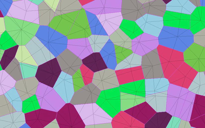
Figure 4-1. A Voronoi diagram
In nature, the Voronoi diagram can be seen on a turtle’s carapace, a giraffe’s skin, the cracks in dried mud, and much more. There are many applications of this pattern in the CGI field, from procedural texture creations to fracturing object simulations.
MAXScript and the Sample Code
MAXScript, the built-in scripting language for Autodesk 3ds Max, provides a number of methods to interact with mesh nodes. These are contained in the meshOp struct, and in the sample code they are used to get/set information from/to the meshes. The snapshotAsMesh command returns a mesh copy of the argument; in my example, it will be used both for performance and for practical matters. MAXScript works faster with Editable Meshes than Editable Polys; another advantage of Editable Meshes is that they provide access to the explicit triangles of the object. To improve the performance of the script, the suspendEditing() and resumeEditing() methods, which disable the Modify Panel interface during execution, will be used. In MAXScript, custom-generated meshes are created using the mesh() command with two arrays as its arguments: an array of vertices and an array of faces.
Voronoi and Delaunay
To generate a Voronoi diagram, the sample code uses a property of the Delaunay triangulation. Given a set of vertices, P, it’s a Delaunay triangulation, DT(P), if no point of this set is inside the circumcircle3 of any triangle of DT(P). Figures 4-2 through 4-4 illustrate this process (source: en.wikipedia.org/wiki/Delaunay_triangulation).
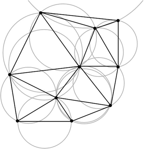
Figure 4-2. Delaunay triangulation for a set of points
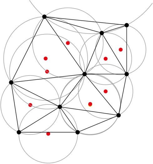
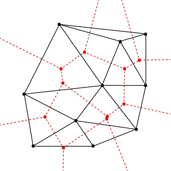
Figure 4-4. Voronoi diagram drawn in red
The Voronoi diagram is created by connecting all the centers of the triangle’s circumcircles sharing the same vertex obtained during the Delaunay triangulation. Further information about Voronoi diagram building and the Delaunay triangulation is available in the references section.
The rest of this chapter illustrates how to build the Voronoi diagram. I will demonstrate
- How to populate an existing mesh with more vertices to create random set of points to triangulate.
- An algorithm to compute the triangulation of the point set.
- How to build the Voronoi diagram connecting the centers of the circumcircles of every triangle in the Delaunay mesh.
Figure 4-5 illustrates these steps.
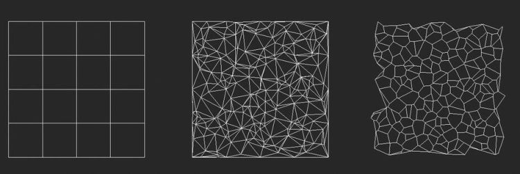
Figure 4-5. From left to right, the base mesh, the Delaunay triangulation mesh, and the resulting Voronoi diagram
What the Script Does
The script you are going to build will be composed of three main procedures and some utility functions:
- fn_delaunayTriangulation is the procedure used to create a random point distribution over the XY plane, or, if a mesh is passed as an argument, inside its triangles using barycentric coordinates. This function will return a triangulated mesh.
- fn_voronoiDiagram is the procedure used to derive the Voronoi diagram using the triangulated Delaunay mesh.
- ut_compareAngle is a utility procedure used to find the right order in which to build each Voronoi polygon.
- ut_compareVx is used to order the vertex array along the X axis.
- ut_isTriangleContained checks to see if a triangle is inside the Delaunay triangle array yet or needs to be added.
- ut_isInsideCircumcircle checks to see if a vertex is inside a triangle’s circumcircle.
Two simple data structures will be defined to help the computation:
- struct triangle(p1,p2,p3) to store triangle data
- struct tEdge(p1,p2) to store edge data during the swapping stage in the Delaunay triangulation
The Code: Utility Functions and Data Structures
The Voronoi diagram computation code is based on two main procedures, one for the Delaunay triangulation and one to achieve your diagram. But to get more readable and practical code, you need some utility procedures and data structures. Two very simple data structures are used in the code, one storing a single triangle and one for the triangle’s edges:
- struct triangle (p1,p2,p3) defines a triangle
- struct tEdge (p1,p2) defines an edge, used to mark the triangle’s edge to split
These structs will be used in the next procedures as array elements. The p1..p3 variables will contain vertices in 2D or 3D spaces. They are needed to store information about the triangle’s edges to find the right ones to swap or delete from the Delaunay triangulation mesh.
fn ut_compareAngle v1 v2 =
(
  if(v1.z < v2.z) then return -1
  else return 1
)
The function ut_compareAngle will be used to compare the angles between the Voronoi cell center and its surrounding vertices to find the right order to get a proper convex polygon. MAXScript lets the user define his own compare function to sort arrays containing complex elements. According to the MAXScript documentation, the qsort command takes the array and a comparison function as input. This comparison procedure will take two values as arguments and return 0 if the values are equivalent, -1 if the first value is less than the second value, and 1 in the other case.
fn ut_compareVx v1 v2 =
(
  if(v1.x < v2.x) then return -1
else if(v1.x > v2.x) then return 1
  else return 0
)
The ut_compareVx procedure will be used to compare two vertices and order their array along X axis values.
fn ut_isInsideCircumcircle p t &circumCircle =
(
  --check for the coincidence
  if( abs(t.p1.y - t.p2.y) == 0 and abs(t.p2.y - t.p3.y) == 0 ) then
  (
    print("error, coincidence
");
    return false
  )

  if(abs(t.p2.y - t.p1.y) == 0) then
  (
    m2 = -(t.p3.x - t.p2.x) / (t.p3.y - t.p2.y)
    mx2 = (t.p2.x + t.p3.x) / 2.0
    my2 = (t.p2.y + t.p3.y) / 2.0
    circumCircle.x = (t.p2.x + t.p1.x) / 2.0
    circumCircle.y = m2 * (circumCircle.x - mx2) + my2
  )
  else if ( abs(t.p3.y-t.p2.y) == 0 ) then
  (
    m1 = - (t.p2.x-t.p1.x) / (t.p2.y-t.p1.y)
    mx1 = (t.p1.x + t.p2.x) / 2.0
    my1 = (t.p1.y + t.p2.y) / 2.0
    circumCircle.x = (t.p3.x + t.p2.x) / 2.0
    circumCircle.y = m1 * (circumCircle.x - mx1) + my1
  )
  else
  (
    m1 = - (t.p2.x-t.p1.x) / (t.p2.y-t.p1.y)
    m2 = - (t.p3.x-t.p2.x) / (t.p3.y-t.p2.y)
    mx1 = (t.p1.x + t.p2.x) / 2.0
    mx2 = (t.p2.x + t.p3.x) / 2.0
    my1 = (t.p1.y + t.p2.y) / 2.0
    my2 = (t.p2.y + t.p3.y) / 2.0
    circumCircle.x = (m1 * mx1 - m2 * mx2 + my2 - my1) / (m1 - m2)
    circumCircle.y = m1 * (circumCircle.x - mx1) + my1
  )

  --check on distances and circumcircle radius
  dx = t.p2.x - circumCircle.x
  dy = t.p2.y - circumCircle.y
  rsqr = dx*dx + dy*dy
  circumCircle.z = sqrt(rsqr) --radius

  dx = p.x - circumCircle.x
  dy = p.y - circumCircle.y
  drsqr = dx*dx + dy*dy    --point distance

  if(drsqr <= rsqr) then return true
)
The ut_isInsideCircumcircle procedure checks to see if point p is inside the t triangle and stores the circumcircle attributes in the circumcircle variable. The & before a variable means that its value will be modified by the function. After a check for a degenerate triangle, the function finds the circumcircle for the current triangle, and using simple distance checks, discovers whether the passed vertex is inside or outside the circle. The circumcircle variable is a simple vector using its x and y components to store circumcircle center 2D coordinates and the z component to store the circumcircle radius. A degenerate triangle has collinear vertices; it is basically a segment.
The Code: the Delaunay Triangulation
This function starts from a mesh, and procedurally adding vertices inside its triangles (to get more interesting Delaunay meshes from simple objects) finds the triangulation solution; it uses the barycentric coordinate system to create more vertices inside a single triangle, expressing them based on an interpolation of the triangle’s vertices coordinates. After generating the right set of vertices, a big triangle surrounding all the vertices is created, and vertex by vertex, a contain-check is performed. At this stage, new triangles are added to the Delaunay set and some are deleted, too.
For readability, I will examine the Delaunay triangulation function code in sections, starting with Listing 4-1.
Listing 4-1. The First Section of the Delaunay Triangulation Function Code
function fn_delaunayTriangulation vNumber baseMesh =
(
  --the triangles created during the triangulation
  local delunayTriangles = #()

  --contains the vertices to triangulate
  local vertices = #()

  --disable editing for speed
  suspendEditing()

  --mesh copy of the passed object
  customShapeMesh = snapshotAsMesh baseMesh

  --for every triangle in the mesh generate a random set of vertices inside it
  numFaces = meshop.getNumFaces customShapeMesh
  numVertices = meshop.getNumVerts customShapeMesh

  undo off
  (
    for i=1 to numFaces do
    (
      --get the coordinates of the three vertices
      triVertices = meshop.getVertsUsingFace customShapeMesh i
      vertexCoords = #()
      for j=1 to numVertices do
      (
        if(triVertices[j] == true) then
        (
          vertexCoords[(vertexCoords.count + 1)] = meshOP.getVert customShapeMesh j
        )
      )
      --generate some random points inside the triangle using barycentric coords
      for k = 1 to vNumber do
      (
        aa = random 0.0 1.0
        bb = random 0.0 1.0
        if(aa+bb > 1.0) then
        (
          aa = 1-aa
          bb = 1-bb
        )
        cc = 1.0 - aa - bb

        tempV = (aa * vertexCoords[1]) + (bb * vertexCoords[2]) + (cc*vertexCoords[3])
        append vertices tempV
      )
    )
    --append the customShapeMesh vertices too
    for j=1 to numVertices do
    (
      append vertices (meshOP.getVert customShapeMesh j)
    )
  )
-------------------
-- continue below
-------------------
The fn_delaunayTriangulation function takes two arguments. vNumber contains the number of new vertices that will be created inside each triangle of your existing geometry; baseMesh is the existing geometry. Please note that using a high value in vNumber could slow down the MAXScript computation time.
The barycentric coordinates are used to add vertices in triangles defined by the passed mesh: a point inside a triangle can be expressed in terms of triangle’s vertices coordinates, using the following notation:
newVertex = a * tP1 + b * tP2 + c * tP3
a + b + c = 1.0
c = 1.0 - a – b
The sum of a, b, and c must be equal to 1, so generating a and b randomly (checking their sum, too), the c value will equal 1.0 minus a minus b.
At last, the vertices of the passed mesh will be added to your set, as in Listing 4-2.
Listing 4-2. The Vertices of the Passed Mesh Are Added to the Set.
-------------------
-- continue above
-------------------

--sort the vertex array over the x axis
  qsort vertices ut_compareVx

  --find the point plane bounds --> min MAX
  xmin = vertices[1].x
  ymin = vertices[1].y
  xmax = xmin
  ymax = ymin

  for p in vertices do
  (
    if(p.x < xmin) then xmin = p.x
    if(p.x > xmax) then xmax = p.x
    if(p.y < ymin) then ymin = p.y
    if(p.y > ymax) then ymax = p.y
  )

  dx = xmax - xmin
  dy = ymax - ymin

  if(dx > dy) then dmax = dx
  else dmax=dy

  xmid = (xmax + xmin) / 2.0
  ymid = (ymax + ymin) / 2.0

  --create the super triangle containing all the vertices in the array
  superTriangle = triangle [(xmid - 2*dmax), (ymid - dmax), 0.0] [xmid, (ymid + 2*dmax), 0.0] [(xmid + 2*dmax), (ymid - dmax), 0.0]
  append delunayTriangles superTriangle

  --include each vertex one at time and do triangulation
  for p in vertices do
  (
    --setup the edge buffer
    edges = #()

    --for all the triangles currently in the triangulated mesh, do the check
    for j = delunayTriangles.count to 1 by -1 do
    (
      t = delunayTriangles[j]
      circumCircle = [0,0,0]      --contains a circle using xy for the center and z for the radius

      --check if point p is inside the circumcircle of the current triangle
      inside = ut_isInsideCircumcircle p t circumCircle
      if(inside == true) then  --store the edges and delete the triangle from the triangulation
      (
        tedg = tedge t.p1 t.p2
        append edges tedg
        tedg = tedge t.p2 t.p3
        append edges tedg
        tedg = tedge t.p3 t.p1
        append edges tedg
        deleteItem delunayTriangles j
      )
    )

    --tag multiple edges to prevent their use when creating triangles
    for j=1 to edges.count do
    (
      e1 = edges[j]
      for k = j+1 to edges.count do
      (
        e2 = edges[k]
        if(e1.p1 == e2.p2 and e1.p2 == e2.p1) then
        (
          e1.p1 = [-1,-1]
          e1.p2 = [-1,-1]
          e2.p1 = [-1,-1]
          e2.p2 = [-1,-1]
        )
      )
    )

    --form new triangles using the remaining edges and current vertex
    for j=1 to edges.count do
    (
      ee = edges[j]
      if (ee.p1 == [-1,-1] or ee.p2 == [-1,-1]) then
        continue

      t = triangle ee.p1 ee.p2 p
      append delunayTriangles t
    )
  )

  --remove the supertriangle and its vertices
  for i=delunayTriangles.count to 1 by -1 do
  (
    t = delunayTriangles[i]
    if (t.p1 == superTriangle.p1 or t.p2 == superTriangle.p2 or t.p3 == superTriangle.p3 or
      t.p1 == superTriangle.p1 or t.p2 == superTriangle.p3 or t.p3 == superTriangle.p2 or
      t.p1 == superTriangle.p2 or t.p2 == superTriangle.p3 or t.p3 == superTriangle.p1 or
      t.p1 == superTriangle.p2 or t.p2 == superTriangle.p1 or t.p3 == superTriangle.p3 or
      t.p1 == superTriangle.p3 or t.p2 == superTriangle.p1 or t.p3 == superTriangle.p2 or
      t.p1 == superTriangle.p3 or t.p2 == superTriangle.p2 or t.p3 == superTriangle.p1
      ) then
      deleteItem delunayTriangles i
  )
-------------------
-- continue below
-------------------
Using the compare utility function, the vertex array is sorted along the X axis. Next, the bounding box of all the vertices is computed and a super-triangle surrounding the set of all the vertices is generated. One by one, all the vertices are compared to the triangles currently inside the triangulation set, and based on the inside-circumcircle check, new triangles are added or the existing ones are modified. At the end of this process, the super-triangle is deleted from the Delaunay set (see Listing 4-3).
Listing 4-3. The Final Delaunay Mesh
-------------------
-- continue above
-------------------
--create a mesh to see the results
  for t in delunayTriangles do
  (
    v=#()
    append v t.p1
    append v t.p2
    append v t.p3

    f=#([1,2,3])
    mm = mesh vertices:v faces:f
    mm.name = uniqueName "tri_000"
  )

  --select all the tri meshes and attach them to a void mesh
    delaunayMesh = editable_mesh()
    delaunayMesh.name = uniqueName "delaunayMesh_"
    deselect $*
    for i in $*tri_* do
      meshop.attach delaunayMesh i

    convertTo delaunayMesh PolyMeshObject
    polyop.weldVertsByThreshold delaunayMesh #{1..(delaunayMesh.GetNumVertices())}

  resumeEditing()
  return delaunayMesh
)
--end fn_delaunayTriangulation function
For every triangle in the Delaunay triangle array, a single mesh is created and later attached to a void mesh. The duplicated vertices are finally welded together. Figure 4-6 shows the base mesh and the results of the fn_delaunayTriangulation function. Notice how the triangles in the base mesh have been subdivided.
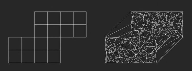
Figure 4-6. Base mesh and Delaunay mesh
The Code: the Voronoi Diagram
The Voronoi diagram procedure is pretty simple: it takes as arguments the triangulated Delaunay mesh, a numerical value used to delete Voronoi polygons of the same side amount, and the mesh used as the base for the triangulation. The base mesh is needed to cut out all the Voronoi polygons that lie outside it.
Every vertex in the triangulated mesh is a Voronoi cell center, and the centers of the triangles sharing the vertex are the cell vertices. So for every vertex in the triangulated mesh, you get all the faces that are sharing it, and for every face, you find the circumcircle center. The angle between the current vertex and the surrounding centers is calculated and stored in an array. This array will be ordered using a utility function. Finally, the new polygon is added to the Editable Poly object created in the first lines of the procedure (see Listing 4-4).
Listing 4-4. Creating the Voronoi Diagram
function fn_voronoiDiagram outTriMesh cutNgons baseMesh =
(
  --the object for the voronoi polys
  voronoiDiagram = editable_mesh()
  voronoiDiagram.name = uniqueName "voronoiPoly"
  convertTo voronoiDiagram PolyMeshObject

  suspendEditing()

  undo off
  (
    numVertex = polyOp.getNumVerts outTriMesh
    for j = 1 to numVertex do
    (
      --for every face sharing the vertex
      faces = polyop.getFacesUsingVert outTriMesh j
      polyVertices = #() --vertices of the new face
      indexFace = #() --the face, contains vertices index...all the v[]
      for i = 1 to faces.count do
      (
        if faces[i] == true then
        (
          --get the face
          curF = polyOp.getFaceVerts outTriMesh i
          --find the center of the face and add to the polygon list
          x1 = (polyOp.getVert outTriMesh curF[1]).x
          x2 = (polyOp.getVert outTriMesh curF[2]).x
          x3 = (polyOp.getVert outTriMesh curF[3]).x
          y1 = (polyOp.getVert outTriMesh curF[1]).y
          y2 = (polyOp.getVert outTriMesh curF[2]).y
          y3 = (polyOp.getVert outTriMesh curF[3]).y

          D = 2*( x1*(y2 - y3) + x2*(y3 - y1) + x3*(y1 - y2))

          A = ( ((y1*y1 + x1*x1)*(y2 - y3)) + ((y2*y2 + x2*x2)*(y3 - y1)) + ((y3*y3 + x3*x3)*(y1 - y2)) )
          A = A / float(D)
          B = ( ((y1*y1 + x1*x1)*(x3 - x2)) + ((y2*y2 + x2*x2)*(x1 - x3)) + ((y3*y3 + x3*x3)*(x2 - x1)) )
          B = B / float(D)

          --check for the center, if it's inside the plane or inside the passed mesh it's ok
          if(baseMesh != "undefined") then
          (
            --check if the center is inside the triangles of the mesh using the barycentric coords properties
            customShapeMesh = snapshotAsMesh baseMesh

            numFaces = meshop.getNumFaces customShapeMesh
            numVertices = meshop.getNumVerts customShapeMesh

            --for every triangle:
            for i=1 to numFaces do
            (
              --get the three vertices
              triVertices = meshop.getVertsUsingFace customShapeMesh i
              vertexCoords = #()
              for j=1 to numVertices do
              (
                if(triVertices[j] == true) then
                (
                  vertexCoords[(vertexCoords.count + 1)] = meshOP.getVert customShapeMesh j
                )
              )

              --compute the vectors
              P = [A, B, 0]
              v0 = vertexCoords[3] - vertexCoords[1]
              v1 = vertexCoords[2] - vertexCoords[1]
              v2 = P - vertexCoords[1]

              --compute the dot products
              dot00 = dot v0 v0
              dot01 = dot v0 v1
              dot02 = dot v0 v2
              dot11 = dot v1 v1
              dot12 = dot v1 v2

              -- Compute barycentric coordinates
              invDenom = 1 / (dot00 * dot11 - dot01 * dot01)
              u = (dot11 * dot02 - dot01 * dot12) * invDenom
              v = (dot00 * dot12 - dot01 * dot02) * invDenom

              --Check if point is in triangle
              if (u > 0 and v > 0 and u + v < 1 ) then
              (
                append polyVertices [A, B,0]
                --exit --exit from the for loop
              )
            )
          )
        )
      )

      --find all the angles between the current vertex and all the voronoi vertices
      A = polyOp.getVert outTriMesh j
      for k = 1 to polyVertices.count do
      (
        --find the angle of B relative to A
        B = polyVertices[k] - A
        angl = (atan2 B.y B.x)
        polyVertices[k].z = angl
      )

      --sort using angle --> z value
      qsort polyVertices ut_compareAngle

      --restore the z value to zero, this value was previously used to store the angle value!
      for k = 1 to polyVertices.count do polyVertices[k].z = 0.0

      --should have quads polys and not ngons...
      indexVertex = #()
      for k=1 to polyVertices.count do
      (
        append indexVertex (polyOp.createVert voronoiDiagram polyVertices[k])
      )

      --check for triangle faces
      if(indexVertex.count > cutNgons) then
        polyop.createPolygon voronoiDiagram indexVertex
    )
  )
  resumeEditing()
  return voronoiDiagram
)
To run the scripts and check the results on a base mesh, just execute the following code. The results should be similar to those shown in Figure 4-7. The mesh must be placed in the “top” view (y and x coordinates only).
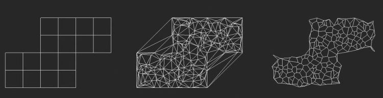
Figure 4-7. Base mesh, Delaunay mesh, and Voronoi diagram
baseMesh = $
outTriMesh = fn_delaunayTriangulation 8 baseMesh
fn_voronoiDiagram outTriMesh 2 baseMesh
Conclusion
This chapter offers an introduction to procedural geometry creation using the tools offered by MAXScript. The proposed Voronoi diagram computation code is basic and could be improved in a variety of ways. For example, the bounding edges of the base mesh are not considered or included in the resulting Voronoi diagram mesh. The code works only for planar base meshes and doesn’t work in object space. The reader could improve it by removing the world space-only limitation and adding the base mesh boundary vertices to the Voronoi mesh to achieve the breaking surface effect.
________________
1“Voronoi diagram.” http://en.wikipedia.org/wiki/Voronoi_diagram.
2“Georgy Voronoy.” http://en.wikipedia.org/wiki/Georgy_Voronoy.
3“Circumscribed circle.” http://en.wikipedia.org/wiki/Circumscribed_circle.