
![]()
Moving Tools to the Cloud: Control, Configure, Monitor, and View Your Game with WebSocket
John McCutchan
Your engine needs great tools because they increase developer and artist productivity. Engine tools will automate tasks such as baking assets or regression testing, but they’re not just for automation; they are also companion applications that allow you to control, configure, monitor, and view your engine.
At the highest level, engine tools can be split into two categories: tools that communicate directly with an engine while it is running, and tools that run independent of the engine. Examples of the latter include mesh bakers and graphics shader compilers. Tools that communicate with the engine are companion applications running along or inside the game engine. A dynamic graph showing the amount of memory presently allocated, a Quake-style command console, and property panels for configuring game objects are examples of companion tools. This chapter focuses on companion tools.
Often embedded inside the running game, companion tools have the benefits of being synchronized and in control of the game engine, but they suffer from a few problems. First of all, they require a GUI framework that can run inside the game. Off-the-shelf GUI frameworks exist, but they often come with large dependencies or inappropriate licenses, or they conflict with the game itself. Second, because companion tools run as part of the engine, there can be long iteration times. A minor change to the tool, such as adding a toggle button, requires that the game be recompiled, relinked, and restarted, incurring the cost of reloading all assets needed to run it. A third problem with companion tools is that console development kits do not have a mouse or keyboard, relegating the UI to harder-to-use input methods like analog sticks, D-pads, and onscreen keyboards. Finally, by coupling the tools to the game instance itself, a developer must be sitting next to the development hardware in order to use them.
Moving these tools out of the game engine and into web applications solves or avoids these problems and gives you a great platform for developing tools. Browsers are ideal for creating rich GUIs with very fast iteration times. Because the tools are browser applications, they are remotely accessible. They’re also easy to distribute because they contain no dependencies other than the browser itself. More important, building the tools as web applications that communicate over the network with an instance of the engine requires a clear separation between tools and the game, with the benefit of cleaner design and a more modular code base.
Web applications are generally considered to be synonymous with “the cloud,” which means that both they and the data they use reside on multiple remote servers accessible via a web browser.
Figure 10-1 shows the separation between the tools and the game communicating via network messages.
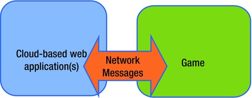
Figure 10-1. Separation of game and tools communicating over the network
Recently, the browser has evolved from being a tool for viewing web sites to an ideal platform for building desktop-quality applications. Browser vendors have adopted HTML5, WebSocket, and WebGL, and are quickly filling in the missing pieces such as gamepad support and mouse locking (needed for first person shooter mouse controls).
The rest of this chapter will present a foundation for building engine tools as browser applications, offer sample applications, and provide technical details involved in building a WebSocket server and JSON-based remote procedure call system.
Foundation
My proposal is to construct an API for engine tools (ET-API), built on a remote procedure call system using JSON for data encoding and the recently standardized WebSocket protocol for network transmission. The tools will run in a browser, so it is important that ET-API is easy to use from there. This section of the chapter will provide concrete definitions of RPC, JSON, WebSocket, etc., while laying a foundation for moving engine tools to the cloud.
What exactly is a remote procedure call system? Simply put, it is a function call from one process to another. The processes do not have to be running on the same machine or share the same architecture. When attempting to understand RPC, it is helpful to first consider a local procedure call in a language like C/C++. When a local procedure call occurs, the arguments are pushed onto the stack, then the program branches to the address of the function being called. When the called function returns, the result is stored on the stack for the calling function to access. This procedure call mechanism works because the caller, callee, and shared data live in the same address space and agree on calling conventions that make use of the shared address space. In a remote procedure call system, the caller, callee, and data do not share an address space and thus cannot share data by memory address. In other words, the calling convention for a remote procedure call system must define not only how arguments are passed and returned, but also the format the arguments are encoded in. In order to make a remote procedure call, you must marshal (encode) the parameters for transmission over the network and pack them into a message for the remote system. Once the message has been prepared, it is transported to the remote process. The return value(s) from an RPC are sent in a similar manner but in the opposite direction.
Because the tools will be running inside a browser, it is important that you pick a data encoding scheme that is native to the browser. I’ve chosen JavaScript Object Notation (JSON) data encoding. (JSON is text-only data encoding that every browser can serialize JavaScript objects into and construct JavaScript objects from.) The primitive types are the keywords null, true, and false, as well as decimal numbers and strings. In addition to the primitive types, JSON has two collections. The first collection is an unordered key/value map. The second collection is an ordered list (or array). Listing 10-1 shows some sample JSON from a player profile.
Listing 10-1. Some JSON from a Player Profile
{
     "PlayerName" : "John McCutchan",
     "RecentScores" : [10000, 12345, 99, 1, 0],
     "TrophyList": [
           { "TrophyName": "5 in a row", "Unlocked": false },
           { "TrophyName": "First Timer", "Unlocked": true }
     ]
}
The special characters { and } begin and end a key/value map. The special characters [ and ] begin and end an ordered list. In Listing 10-1, the root keys are PlayerName, RecentScores, and TrophyList. The value of the TrophyList key is an ordered list of trophies, each having a TrophyName and an Unlocked flag.
Aside from being the native data structure of browser applications, JSON is easily read and written by humans with far less markup than, for example, XML.
Now that the data-marshaling format has been fixed, the next piece of the ET-API puzzle is the RPC message framing, that is, the mandatory portion of the RPC message. Each RPC is a JSON map with two required keys: the message type and the message serial number or ID, as shown in Listing 10-2.
Listing 10-2. The Message Type and the Message ID
{
     "type" : "<type>"
     "id" : "<id>"
}
The type field is used to indicate the type of message. ET-API supports three types: command, result, and report. I will explain each of these shortly.
The ID field is used to pair related messages together. For example, the command shown in Listing 10-3 has an ID of 4.
Listing 10-3. The ID Field Pairs Related Messages Together.
{
     "type" : "command",
     "id" : "4",
     ...
}
The result of the command sent back from the engine to the browser application will also have an ID of 4. This ID makes connecting a function call and return value easy.
Returning to the type field, the possibilities are
- Command: Commands initiate some sort of action or state change.
- Result: The result of a command. Linked together with the id field. Commands are not required to reply with a result.
- Report: A regular, repeating message from a subscription. Clients can subscribe to report channels and set an interval between reports.
All other fields in a message are dictated by the requirements of the command. ET-API has three stock commands:
- Echo: Results in a reply message containing a copy of the message key.
- Subscribe: Caller is subscribed to a report channel.
- Unsubscribe: Caller is unsubscribed from a report channel.
The final piece of the ET-API foundation is the transmission and reception of messages over the network between the browser application and the game engine. ET-API could have used HTTP, but browsers now support a much more efficient network protocol, WebSocket. WebSocket is a communication protocol that allows for bidirectional text and binary message passing. Think TCP for the browser. The WebSocket protocol is very bandwidth efficient (message framing is at most 14 bytes), and the payloads are custom to the application. Since a WebSocket connection is only a thin layer on top of TCP, the latency is low, too.
Examples
With the ET-API foundation in place, I will introduce tools that were created with ET-API. This section will cover sample applications that include asset preview, live monitoring, live editing, remote viewing, and unit testing.
My engine allows for browser tools to preview three asset classes: textures, meshes, and models. Models are a combination of textures, meshes, and shaders. I have not considered audio preview.
The way the tools preview each type of asset is essentially the same. The tool sends a command requesting a specific asset, and the engine sends the asset over as a result. Once the tool receives the asset data, it caches the data locally so the network traffic is minimal. How the asset data is packed depends on the asset class. For a mesh, the index buffer and associated vertex buffers must be sent over. This mesh data is then loaded into WebGL index and vertex buffer objects. For a texture, each slice of the mipmap pyramid must be sent over. Once the entire mipmap pyramid is in the browser, the preview tool can display the texture at each level of detail and overlay texture coordinates on top using the browser canvas.
Live performance monitoring tools are fed data by a reporter. The browser tool subscribes to a reporter and sets an update frequency. Figure 10-2 shows a report from the MemoryGraph reporter.
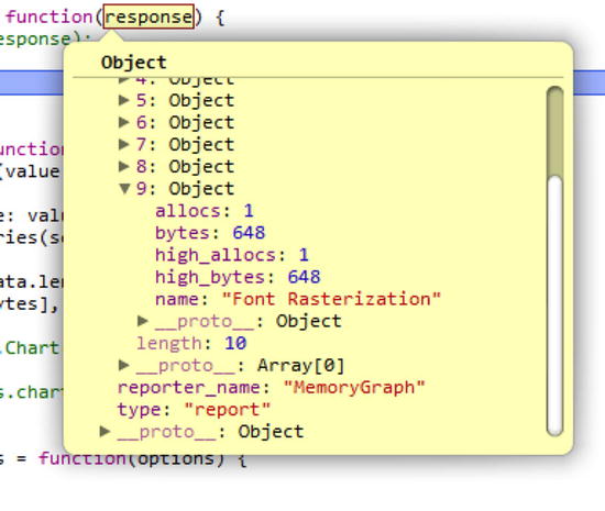
Figure 10-2. A sample message from the MemoryGraph reporter
Each MemoryGraph report includes an array of allocators. For each allocator, the current number of allocations and bytes allocated is included along with the high water mark of each. Figure 10-3 displays this data with a live graph.
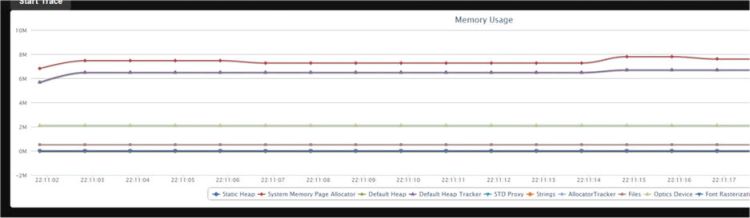
Figure 10-3. Graph of memory usage over time
Live editing is made possible by making all game objects and their properties uniquely identifiable. Once you have this system in place, creating new objects or updating existing objects’ properties becomes a matter of issuing simple commands. For live editing, the appropriate user interface is very game-specific.
A remote viewer tool captures the output from the running game and displays it in the browser. A remote viewer can be taken a step further by having the browser tool send user input back to the engine. My remote viewer application is very simple. The browser tool requests a screenshot from the engine, and after receiving a screenshot, asks for another. By having the request for an updated screenshot come from the browser tool, you don’t force the engine to produce and send more frames than the network can handle. This client request is a very simple form of rate limiting. Figure 10-4 shows the display from a toy demo rendering a tessellated wireframe teapot.
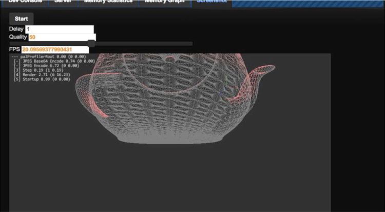
Figure 10-4. Screenshot of remote viewer
It may be hard to make out, but the image is encoded at about 50% JPEG quality and is running at about 20 frames per second. The engine frame buffer was 960 x 540 pixels, and encoding it as a JPEG took about three milliseconds. At medium quality, I was easily able to obtain 30 frames per second with “good enough” image quality. This type of remote viewer requires a large amount of bandwidth. Each frame amounted to about 64 KiB of JPEG data. Running at 30 frames per second, the tool needs 1920 KiB per second. This bandwidth requirement is fine for a local area network (even a WiFi one) but is inappropriate for streaming over the Internet. For reference, the engine was running single-threaded on an Intel Core i5 CPU.
Various forms of testing are possible with an ET-API system. You can do regression testing, for example, by capturing performance data such as memory used. Each day, the engine can be spawned, and a remote browser can create a fixed set of objects while observing total memory used. If this total amount has changed, the tool can notify developers of a potential memory leak. Testing the renderer becomes possible with the remote viewing capabilities. On each test run, the browser tool constructs a scene, places the camera, and requests a screenshot. This screenshot is compared with a previously approved screenshot. If they do not match, a bug may have been introduced into the renderer.
Technical Details
Implementing ET-API for your engine requires a WebSocket server, a system for managing multiple connections, report generators, and command processors. This section will cover each of these in turn.
A WebSocket connection begins life as a regular HTTP connection. The connection is upgraded from HTTP to WebSocket. This upgrade is one-way; you can’t revert back to an HTTP connection. Listing 10-4 shows a sample upgrade request.
Listing 10-4. A Sample Upgrade Request
GET /servicename HTTP/1.1
Host: server.example.com
Upgrade: websocket
Connection: Upgrade
Sec-WebSocket-Key: dGhlIHNhbXBsZSBub25jZQ==
Origin: http://example.com
Listing 10-5 shows how the server responds.
Listing 10-5. Server Response to an Upgrade Request
HTTP/1.1 101 Switching Protocols
Upgrade: websocket
Connection: Upgrade
Sec-WebSocket-Accept: s3pPLMBiTxaQ9kYGzzhZRbK+xOo=
Most of these HTTP fields are self-explanatory, but not Sec-WebSocket-Key and Sec-WebSocket-Accept. Sec-WebSocket-Key is a string sent by the client as a challenge to the server. The challenge is there so that the client is sure that it is communicating with an actual (and up-to-date) WebSocket server. This example leads to the question, how does the server calculate the value of Sec-WebSocket-Accept and complete the challenge? The answer is quite simple. The server first takes Sec-WebSocket-Key and concatenates it with a GUID string from the WebSocket specification. Then the SHA-1 hash of the resulting string is computed, and finally, Sec-WebSocket-Accept is the base64 encoding of the hash value. Let’s work through an example, starting with Listing 10-6.
Listing 10-6. The Connection is Upgraded to WebSocket
SpecifcationGUID = "258EAFA5-E914-47DA-95CA-C5AB0DC85B11";
FullWebSocketKey = concatenate(Sec-WebSocket-Key, SpecifcationGUID);
-> dGhlIHNhbXBsZSBub25jZQ==258EAFA5-E914-47DA-95CA-C5AB0DC85B11
KeyHash = SHA-1(FullWebSocketKey);
-> 0xb3 0x7a 0x4f 0x2c 0xc0 0x62 0x4f 0x16 0x90 0xf6 0x46 0x06 0xcf 0x38 0x59 0x45 0xb2 0xbe 0xc4 0xea
Sec-Websocket-Accept = base64(KeyHash)
-> s3pPLMBiTxaQ9kYGzzhZRbK+xOo=
After the client has successfully completed the challenge, the connection is upgraded from HTTP to WebSocket and all communication must be performed through WebSocket.
Unlike TCP, WebSocket is a message-based protocol. No end of a WebSocket connection can receive a half-transmitted message. At the protocol level, each message begins with a header defining the length of the message, the type (text, binary, or control), and other metadata. The message payload immediately follows the message header. All incoming messages will include a 32-bit mask, which must be applied to the entire payload with an XOR operation. Each message will have a different mask.
The header begins with a 16-bit mask (light background) and up to 12 bytes of optional header (dark background) shown in Figure 10-5.
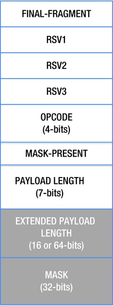
Figure 10-5. WebSocket packet data layout
The header mask indicates whether this packet is the final fragment of a message (messages can be split into fragments), what the opcode is, and whether a mask is present. The payload length field plays double duty. For small messages (less than 125 bytes), it holds the length of the message, but for messages that are longer, the payload length is used as a flag to indicate the size of the extended payload length field. The extended payload length follows immediately after the first 16 bits of the header (it comes before the mask). When payload length is equal to 126, the extended payload length is 16 bits, and when it is equal to 127, the extended payload length is 64 bits.
WebSocket opcodes are split into three categories: continuation, non-control, and control. Continuation and non-control opcodes indicate user messages, and control frames are used to configure the protocol itself. Presently the following opcodes are defined as shown in Table 10-1.
Table 10-1. WebSocket Opcodes
opcode |
Meaning |
|---|---|
0x0 |
Message continuation [continuation] |
0x1 |
Text message [non-control] |
0x2 |
Binary message [non-control] |
0x8 |
Connection Close [control] |
0x9 |
Ping [control] |
0xA |
Pong [control] |
Once you have parsed the header, extracting the payload is trivial. Do not forget to XOR in the mask. Parsing the header is made interesting by the fact that its size and layout are variable and thus cannot be mapped directly to a C structure. However, because each WebSocket message is at least 16 bits, you can define a structure that only reserves 16 bits (a uint16_t) of storage, the optional header fields and payload of the message should immediately follow the header in memory, see Listing 10-7.
Listing 10-7. The WebSocketMessageHeader
struct WebSocketMessageHeader {
   union {
     struct {
       unsigned int OP_CODE : 4;
       unsigned int RSV1 : 1;
       unsigned int RSV2 : 1;
       unsigned int RSV3 : 1;
       unsigned int FIN : 1;
       unsigned int PAYLOAD : 7;
       unsigned int MASK : 1;
     } bits;
     uint16_t short_header;
 };

 size_t GetMessageLength() const;
 size_t GetPayloadOffset() const;
 size_t GetPayloadLength() const;
 uint32_t GetMask() const;
 uint8_t GetOpCode() const;
 bool IsFinal() const;
 bool IsMasked() const;

 ...

};
A WebSocketMessageHeader will always be at least 16 bits long, so the only data element defined inside the struct is short_header. Accessing the mask and extended payload lengths or the payload is done with an offset from &short_header. When I want to parse a header, I simply do this:
WebSocketMessageHeader* header = &buffer[i];
I have found this approach to be very clean; it is generally useful when dealing with structures that do not have a fixed length or layout.
Messages can be split into multiple fragments. When this happens, the FINAL-FRAGMENT bit will be zero until the final message. The first fragment will have the opcode indicating either a text (0x1) or binary (0x2) message, and the rest of the fragments will have the opcode of continuation (0x0).
The protocol supports ping (0x9) and pong (0xA) messages. When a ping message has a payload, the consequent pong message must have an identical payload. You are only required to pong the most recent ping if more than one ping arrives.
A WebSocket Server
Now that the WebSocket protocol is understood, I will describe the high-level design of my WebSocket server. My server uses three buffers: one for incoming WebSocket data, one for outgoing WebSocket data, and one to store fully parsed incoming messages. Listing 10-8 shows an outline of the API.
Listing 10-8. Outline of the WebSocket Server API
class WebSocketServer {
public:
 WebSocketServer();

 int AcceptConnection(TcpListener* listener);
 int CloseConnection();

 void Update();

 int SendTextMessage(const char* msg);
 int SendTextMessage(const char* msg, size_t msg_length);

 uint64_t PendingMessageCount() const;
 void ProcessMessages(OnMessageDelegate del, void* userdata);
 void ClearMessages();
};
![]() Note Some trivial methods have been omitted.
Note Some trivial methods have been omitted.
Listening for a connection over TCP must be decoupled from the WebSocket server itself. Each instance of WebSocketServer is responsible for only one client. This separation keeps the code and resource allocation simple. A higher-level system should manage multiple connection requests and multiple live WebSocket connections.
My WebSocket server has a single Update method. This method pumps the connection. It is responsible for sending any pending messages, receiving any new messages (ultimately moving them to the message buffer), and updating status flags (connection opened, connection closed, connection error).
Complete incoming messages are stored in their own buffer. When the engine system is ready to process incoming messages, a call to ProcessMessages is made and a delegate function is passed in. The WebSocketServer will iterate over all messages in the buffer and call this delegate for each one. When the engine is done with the messages, it must clear them by calling ClearMessages.
I started with the explicit goal of supporting multiple connected clients. I’ve discussed the importance of decoupling the code that waits for a connection over TCP from the code that manages a WebSocket connection. Because of that decoupling, supporting multiple connections is practically free.
Command Processing
Support for commands is added by implementing the commander interface, as shown in Listing 10-9.
Listing 10-9. Implementing the Commander Interface
class doCommandCenterCommanderInterface {
public:
 virtual const char* CommanderName() const = 0;
 virtual bool CanProcessCommand(const doCommandCenterCommandPacket* packet) const = 0;
 virtual void ProcessCommand(doCommandCenterConnection* connection, const doCommandCenterCommandPacket* packet) = 0;
};
A commander can process one or many commands (CanProcessCommand). Each commander is registered with the central command center, which routes messages from connected clients to the appropriate commander. doCommandCenterCommandPacket just contains a parsed JSON object, and doCommandCenterConnection has the WebSocket connection and various buffers in it.
Support for reports is added by implementing the reporter interface, as shown in Listing 10-10.
Listing 10-10. Implementing the Reporter Interface
class doCommandCenterReporterInterface {
public:
   virtual const char* ReporterName() const = 0;
   // Update internal state
   virtual void Refresh() = 0;
   // Report state to all subscribed connections
   virtual void Report() = 0;
};
Each reporter is responsible for generating a single type of report. Similar to commanders, reporters are registered in the central command center.
Client commands to subscribe and unsubscribe are processed by a commander, like all other commands.
Future Work
There are many avenues for future work in browser-based tools. One possibility is a video streaming solution that makes more efficient use of bandwidth while minimizing the CPU load during encoding. It would be interesting to see the game engine and the game play completely isolated from each other. The game play code would use ET-API to remotely script the engine, although latency could make this difficult. Finally, I’d like to extend this approach to offline asset baking. The engine could be notified over ET-API when an asset is baked and could be reloaded.
Conclusion
I am proposing that your engine define an API for engine tools (ET-API). ET-API is exposed as a JSON-based remote procedure call sitting on top of the WebSocket protocol. With ET-API in place, all engine tools are built as browser applications. The engine should support multiple simultaneously connected tools. I have offered examples of a remote viewer, live editing, live performance monitoring, asset preview, and testing. Each of these applications can be cloud hosted, providing a central location for all tools used in a game studio. If these tools allow content to be created, players could be allowed access to them to create add-ons for the game. These examples are just the tip of the iceberg. Although much of this chapter has been devoted to exposing a game written in C/C++ to browser tools, this approach is applicable to game engines written in any language—even a game written for a web browser.