
So far, we have talked about rigid bodies and colliders, but they were just single physical bodies. What about more complex mechanical systems? Imagine a rope that is holding a cage with a skeleton and a key inside. So, our protagonist decides to cut the rope to make the cage fall. Once the rope is broken, then the cage falls down. However, even before the rope is cut, the cage was under the effect of gravity. In fact, if our protagonist would have pushed the cage instead of cutting the rope, that would have started to oscillate. The reason is that the rope is giving a constraint to the cage — it is allowed to move only within a circle (or sphere if we are in 3D) that has per radius the length of the rope. Of course, when it oscillates, gravity makes the cage move on the border of this circle (or sphere). What if the rope were a rigid metal bar? Well, the cage would even have a harder constraint, because now it is forced to be only on the border of the circle (or sphere). And if the rope was a spring? Again, this is another kind of constraint as shown in the following diagram:
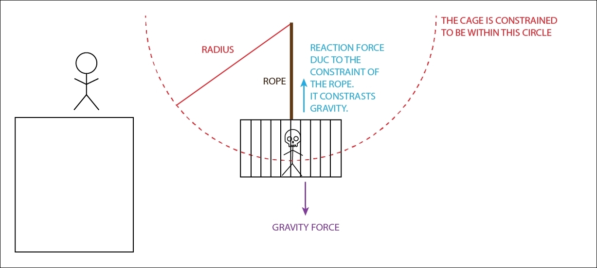
Although the cage is under the force of the gravity, the rope imposes a reaction force. As a result, the cage doesn't fall. Therefore, the rope imposes a constraint on the cage. In particular, it limits the cage motion to be within a circle with a radius equal to the rope length.
Now, imagine placing many of these constraints together. For instance, you tie up the cage to a pending spring, and from the bottom of the cage a rope is holding a metal sphere. The system would start to increase in complexity. But how does Unity handle all of this? The answer is, using Joints components.
Note
Note that all the joints that finish with 2D belong to the 2D Physics engine; otherwise they belong to the 3D one. So be careful to not get confused or attach the wrong joint. However, from now on, we will always refer to it as Joint 2D, even without 2D, unless otherwise specified. This decision was made to make the chapter clear and more fluid to read.
By using a joint component, you can attach a rigidbody to another one, in order to give them a specific constraint, and still leave some freedom for the motion. In particular, Unity provides nine Joint 2D components. But before we go through each one of them, let's explore some general properties of the joints in Unity.
As we've already said, a joint involves two rigidbodies (with the exception of the Target Joint 2D). The first is attached to the same object of the joint. The other one can be chosen arbitrarily. Therefore, these two options are available inside the joint components:
- Enable Collision: Both rigidbodies will have colliders. If this toggle is true, it means that the two rigidbodies will collide between them according to the Physics engine and what we have seen so far in the previous two sections. Most of the times, rigidbodies with a joint belong to the same big system, and you don't want it to collide with itself. As such, the default value is false.
- Connected Rigid body: This is the reference to the second rigidbody of the joint, as the name suggests.
Then, most of the joints (with the exception for the Relative Joint 2D and the Target Joint 2D) needs the two points of the application of the joint. Imagine again the example of the cage pending from the rope. Where the rope is attached to the cage is an important factor, because if the rope is attached to one of the corners of the cage, this will be rotated, as shown in this diagram:
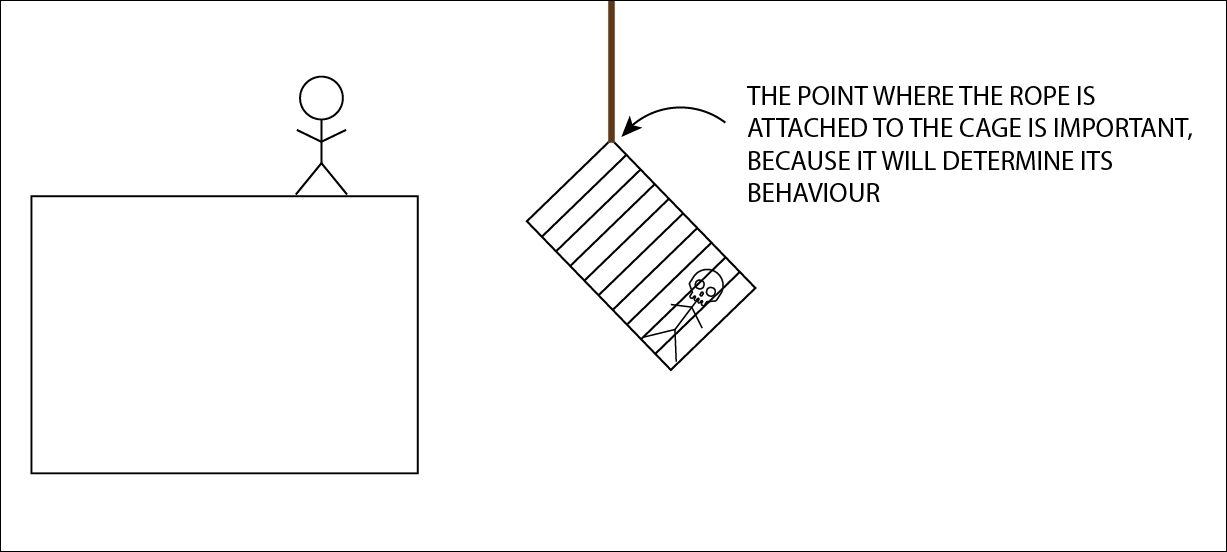
We attached the rope on the cage which is important, because it will affect how it will react to forces. However, it is interesting to note that wherever you append a rigidbody, the line along the rope will pass always through the barycenter (centroid) of the rigidbody.
Plus, you need to consider the possibility that there are other forces that may move the cage, and again where the rope is attached is an important piece of information. The same applies to the other rigidbody; in the case of the cage, the other rigid body is the ceiling.
Therefore, there are some options available to determine these two points of application, which are called anchors in Unity:
- Auto Configure Connected Anchor: If this is checked, Unity will take care to determine where the two anchors are. Of course, turn it off if you have a specific point of application of the joint in mind and you want to place an anchor there.
- Anchor: The position in x and y (with respect to the rigidbody) of the anchor of the joint on the rigidbody where it is attached.
- Connected Anchor : This is the position in x and y (with respect to the rigidbody of the other object) of the anchor of the joint on the rigidbody specified in the Connected Rigidbody variable.
Coming back to the example of the suspended cage, imagine that the hero decides that it is a good idea try to jump on top of the cage and then jump on another platform. However, he didn't consider that the rope was really old (in fact, there is a skeleton in the cage!), and once he landed on the cage, the rope breaks making both the cage and our hero fall. Therefore, it's true that joints impose a constraint, but they have limits too. For the same reason, if you pull both sides of a rubber with too much force, the rubber will eventually break.
Also in Unity, Joints can be broken. In particular, in their components there are two variables:
- Break Force: This is present in all the joints, and it holds the numerical value of the force after which the joint will break. Breaking a joint in Unity means to erase the Joint component from the object. By default, it is set to be infinity, which means that the joint is indestructible. Otherwise, the lower the value, the easier it is to break the joint. In the example of the cage, if we choose to give a very low value for the joint that simulates the rope, it will be likely that the rope is really old and when our hero jumps on top of the cage, they both will fall in the dungeon of the castle.
- Break Torque: This is present in all the joints other than Distance Joint 2D, Spring Joint 2D, and Target Joint 2D. It holds the numerical value of the torque after which the joint will break. As we already have seen, rigidbodies can not only move but also rotate. By default, it is set to be infinity, which means the joint is indestructible. Otherwise, it can be brought to a finite value, allowing the joint to break with torques greater than the value specified.
Note
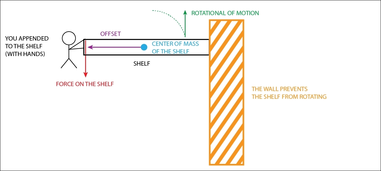
For an example of a joint that breaks under torque, you can just imagine something that is rotating but it's motion is blocked by something, such as when you use the screwdriver and keep going until the wood (which was the constraint) is broken. However, here is another example that is less intuitive but more common (even in video games). Imagine you append yourself on the boarder/edge of a shelf. Since there is an offset from the center of mass of the shelf and the point where you have appended yourself (they are likely to be perpendicular if the shelf is flat), a torque is applied on the shelf. Under the effect of the torque, the shelf should rotate around its center of mass, but it doesn't since the wall prevents it. If you are heavy enough, which means the force you apply on the shelf is greater (or also if in some way you are able to increase the offset), the torque increases, until it reaches a breaking point. Then the constraint will break, which may result either in a broken shelf or a broken wall depending which one has more resistance (most probably the shelf will break and the wall will still stand). The following diagram should help you to figure the example out:
So far, we have seen only general properties of the joints in Unity, but now we will take a closer look at all the nine joint 2D components available.
It's worthy to mention that joints are divided into two classes: spring joints and motor joints. The former uses a spring to impose a constraint, which may be completely stiff so as to simulate a rigid bar. Motor joints, instead, can actively apply forces onto the rigidbodies. Some joints are both, like a spring with a motor.
Tip
All the joints in Unity have an icon (visible when, for instance, you place the component in the Inspector). In this book, you can see the icon in the top-left corner of the images of the joints (in the next sections). This icon is really useful for remembering what the joint does and also how it works. So, when reading the next section, or programming your game, pay attention to this icon, which might help you to understand the joint better.
This joint keeps the two rigidbodies at a certain distance apart. The aim of this joint is to keep at a certain distance two rigidbodies, or a rigidbody and a fixed point in the game world. In fact, if you set the Connected Rigidbody variable to None, you can then specify the position of the fixed point in Connected Anchor.
It should appear like the following in the Inspector:
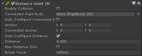
This joint applies a linear force to both the rigidbodies (or just to the rigidbody on which it is attached if using a fixed point) with a very stiff simulated spring (which is not configurable) to keep the distance. The joint doesn't apply any torque.
In addition to the parameters that we have seen in the last section, Distance Joint 2D also has the following options:
- Auto Configure Distance: If set to true, Unity will calculate the current distance between the two rigidbodies (or the rigidbody and the fixed point) and place its value in the Distance variable.
- Distance: Specifies the distance beyond which the two rigidbodies (or the rigidbody and the fixed point) cannot go further.
- Max Distance Only: If enabled, the distance between the two rigidbodies (or the rigidbody and the fixed point) can be lower than the value specified in the Distance. If this option is disabled instead, the distance is fixed and the two points cannot be any further or closer than the Distance.
When Max Distance Only is false, the constraint among the two points is rigid, so you can imagine them connected by a metal string/bar along with a hinge (since they can still rotate with respect to each other). An example of how this is used is when you need to connect two couches of a train together, because they cannot get any farther or closer than a specific distance. If Max Distance Only is true, instead, they can be closer than the Distance, but not further. This is the behaviour of our rope, which holds the cage. that potentially can get closer to where the rope is tied but not further. Another example is a dog with a leash.
However, it is important to keep in mind that both the rigidbodies are free to rotate with respect to each other. In fact, this joint imposes the constraint only on the relative position of the two rigid bodies.
The aim of this joint is to keep a certain relative offset (both linear and angular) between two rigidbodies or a rigidbody and a fixed point in the game world (you can specify it by setting Connected Rigidbody to None).
It should appear like the following in the Inspector:
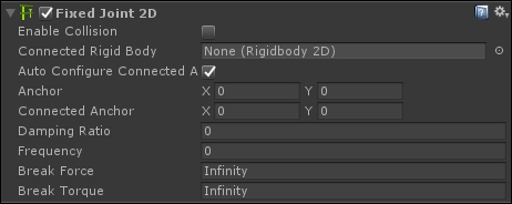
This joints applies both a linear force to compensate the linear offset, and a torque to compensate the angular one. Like Distance Joint 2D, it uses a very stiff simulated spring, but you can tweak the spring values, such as the frequency.
Therefore, in addition to the parameters we have seen in the last section, Fixed Joint 2D has also the following options:
- Damping Ratio: This defines the degree to which the oscillation of the spring is suppressed. Its value ranges from 0 to 1; the higher the value, the less motion. As you would expect from a spring, this joint will overshoot the desired distance and then rebound back, leading the spring to oscillate. The Damping Ratio determines how quickly the oscillation is damped (reduced) and thus how fast the spring comes back to its rest position
- Frequency: This defines the frequency at which the spring oscillates when the rigidbodies are reaching the separation distance. It is measured in cycles per second, and its value ranges from 1 to 1 million. The higher the value, the stiffer the spring, which means less motion. It's worthwhile to notice that a value of zero means that the spring is completely stiff.
Another way to think of this joint is like parenting GameObjects within the Hierarchy so that the children are fixed with respect to their parents. However, the joint offers you more options than a simple parenting, including the possibility to break it.
An example of usage of this joint is when you have a chain of rigidbodies (such as a real chain that hangs from the ceiling, or you can imagine also a bridge made of sections), and you want to hold them rigidly together. The advantage is that you can allow a certain flexibility in the joint, so in the case of the bridge, it can still bend a little within the limits you impose.
The aim of this joint is to keep to zero both the linear and angular offset, by slowing down the movement between the two rigidbodies or a rigidbody and a fixed point in the game world (you can specify it by setting Connected Rigidbody to None).
Friction Joint 2D should appear like this in the Inspector:
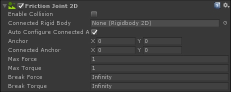
In addition to the parameters we have seen in the last section, Friction Joint 2D has the following options:
- Max Force: This determines the linear resistance along the line that connects the two rigidbodies. A high value (the maximum is 1,000,000) creates a strong linear resistance; thus the two rigidbodies will not move along the line that connects them much. On the contrary, a low value allows more motion.
- Max Torque: This determines the angular resistance between the two rididbodies. A high value (the maximum is 1 million) creates a strong angular resistance; thus the two rigidbodies will not rotate much relatively. On the contrary, a low value allows more motion.
An example of the use of this joint is when there are physical objects in the game that need friction to be believable. So, imagine a platform that is anchored to a big wheel in the background. Since the game is 2D, the wheel is only an aesthetic element; it doesn't actually affect the platform. As such, we need to simulate the friction between the platform and the wheel, and we can achieve that with a Friction Joint 2D. In this way, we can have an angular resistance on the platform; thus it can still be rotated, but not so easily. Maybe, the player may drop a heavy box on the border of the platform to make it rotate enough so that the player can pass.
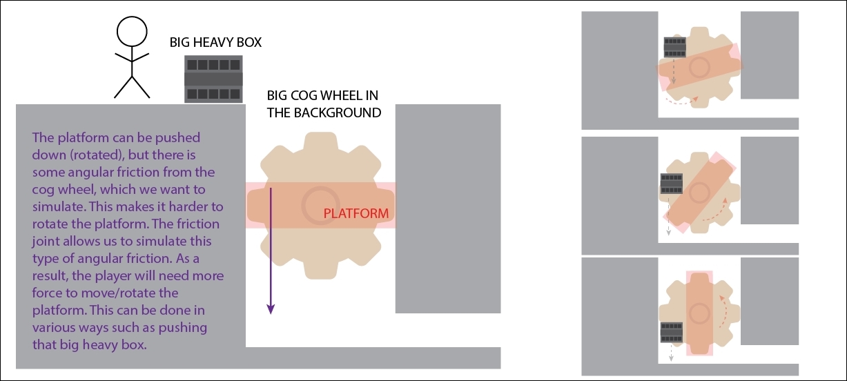
On the left is the representation of the system. On the right is what will happen when the box is dropped onto the platform, which will rotate slowly due its angular friction.
The aim of this joint is to constrain the rigidbody to rotate around another rigidbody or a fixed point in space (always specified by Connected Anchor if Connected Rigid Body is set to None). The rotation can either be left to happen passively (for example, in response to a collision, or under the effect of gravity) or be actively powered by a motor, which provides torque to the rigidbody. Furthermore, limits can be set to constrain the hinge just to rotate at certain angles, or to allow more than a one full rotation around its axis.
It appears like the following screenshot in the Inspector:
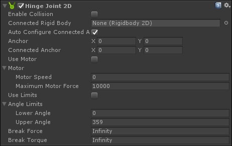
In addition to the parameters that we have seen in the last section, Hinge Joint 2D has the following options:
- Use Motor: If enabled, it allows the joint to actively apply a torque on the rigidbody, simulating a motor.
- Motor Speed: This specifies at which speed the simulated motor should rotate in degrees per second. So a value of 30 means that the motor will do a complete rotation in 12 seconds (360/30=12).
- Maximum Motor Force: This specifies the maximum force that the motor can apply to reach the Motor Speed. Imagine a very heavy object requires a stronger force to rotate and thus reach the Motor Speed. If the motor is not powerful enough, it won't make the rigidbody reach the Motor Speed. Moreover, if a Break Torque is specified, it may break the joint.
- Use Limits: If true, the joint limits the angles to which the rigidbody can rotate.
- Lower Angle: This sets the lower end of the rotation arc allowed by the limit.
- Upper Angle: This sets the upper end of the rotation arc allowed by the limit.
A clear example of the usage of this joint is with doors. They can rotate around their hinges, which connect the door with its frame. We can limit how the door can rotate, so for instance, you may want it to rotate only of 90 degrees. Moreover, if the door is automatic, we can simulate a motor, which actively makes the door rotate. In fact, the motor may be triggered by a script. Finally, if the player wants to push the door beyond its limit (90 degrees in the example), and a Break Torque is specified, the player may break the hinge with enough force.

Top view (birds-eye view). On the left is the representation of the system. On the right is what will happen when the player pushes the door beyond its limits.
This joint makes two rigidbodies to keep a relative position based on each other's position. In fact, the aim of this joint is the same as that of the Fixed Joint 2D; the difference lies in how they do it. The Fixed Joint 2D, as we already have seen, is a spring kind of joint that will stop to oscillate only when the two rigidbodies are at the specified offset and rotation, and so the spring is in a rest position. Instead, the Relative Joint 2D is a motor kind of joint that applies a direct force and torque to rigidbodies so that they are at the same offset and rotation.
Like the Fixed Joint 2D, the Relative Joint 2D can also work with both of these:
- Two rigidbodies
- A rigidbody and a fixed point
To use the second case, set Connected Rigidbody to None and then specify the coordinate of the fixed point in the Linear Offset variable.
It appears like this in the Inspector:
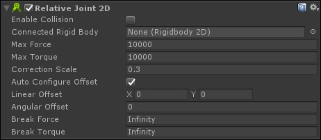
In addition to the parameters we saw in the last section, the Relative Joint 2D has the following options:
- Max Force: This specifies the maximum force that the joint/motor can use to correct the offset between the two rigidbodies. The higher the value, the better the simulated motor will be able to correct the offset. By default, Max Force is set to
10000, which means a really powerful motor. - Max Torque: This specifies the maximum torque that the joint/motor can use to correct the angular offset between the two rigidbodies. The higher the value, the better the simulated motor will be able to correct the angular offset. By default, Max Torque is set to
10000, which means a really powerful motor. - Correction Scale: Tweaks the joint to make sure that it behaves as it is supposed to. This can be done by either increasing Max Force or Max Torque, which may affect behaviour (and as a result the joint may not reach its target). Therefore, you can use this setting to correct it. The default setting of
0.3is usually appropriate (because on an average the joint behaves as you would expect; it's a value that has likely been found by trial and error). But it may need tweaking between the range of 0 and 1. - Auto Configure Offset: When checked, this takes the current linear and angular offsets of the two rigidbodies, stores them in the Linear Offset and Angular Offset variables, and maintains them.
- Linear Offset: This specifies the linear offset that the two rigidbodies should have, expressed in local coordinates.
- Angular Offset: This specifies the angular offset that the two rigidbodies should have, expressed in local coordinates.
An example of use of this joint is between the camera and the Avatar in the game. In this way, the camera can follow the Avatar with a slight delay (because if the camera is parented, it will move instantaneously with the Avatar). But it won't oscillate much as with the Fixed Joint 2D, since it is a spring kind, which may cause frustration to the player (of course, this also depends on how the Fixed Joint 2D is configured, maybe with a real stiff spring; but usually the Relative Joint 2D is used for this kind of situations).
Another typical example of the use of this joint is when something should follow the player, such as a life counter above her head or a friendly spirit behind her shoulders.
Imagine you want to constrain the motion of a rigidbody just along a line, so that it can only slide onto that line. This is what the Slider Joint 2D allows you to do. As for the other joints, the line can be between two rigidbodies or a rigidbody and a fixed point in the game world.
It appears like this in the Inspector:
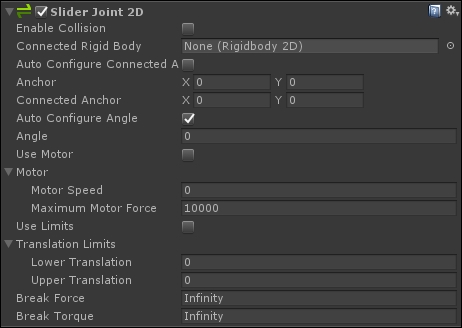
In addition to the parameters we have seen in the last section, the Slider Joint 2D also has the following options:
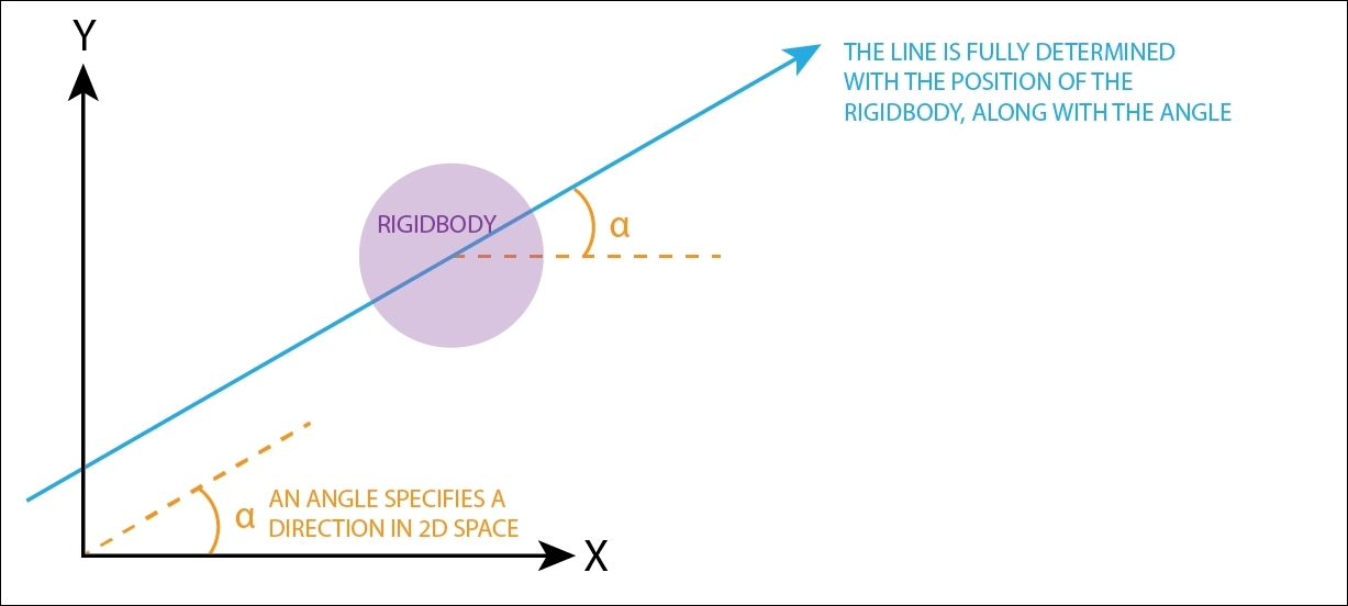
- Angle: This specifies the angle at which the rigidbody is constrained to remain. In the 2D world, an angle fully specifies a direction, and this angle specifies in which direction the motion is constrained.
Note
In order to fully determine the line where motion is allowed by the joint, the current position the rigidbody is taken into consideration as well. Thus, a point (the current position of the rigidbody) and a direction (specified from the Angle variable) univocally determine a line where the motion is constrained, as shown in the following diagram:
- Use Motor: If true, the joint uses a simulated motor as well.
- Motor Speed: This specifies the speed of the rigidbody that the motor should achieve.
- Max Motor Force: This specifies the maximum force that the motor can use/apply in order to achieve a Motor Speed for the rigidbody.
- Use Limits: If true, this allows further constraints on the rigidbody along a segment of the line.
- Lower Limit: This specifies the minimum distance the rigidbody should be at from the Connected Anchor point.
- Upper Translation: This specifies the maximum distance the rigidbody should be at from the Connected Anchor point.
Typical scenarios where you may want to use this joint are a sliding door, which goes up and down, and also a platform, which can go left and right, up, down, or even diagonally.
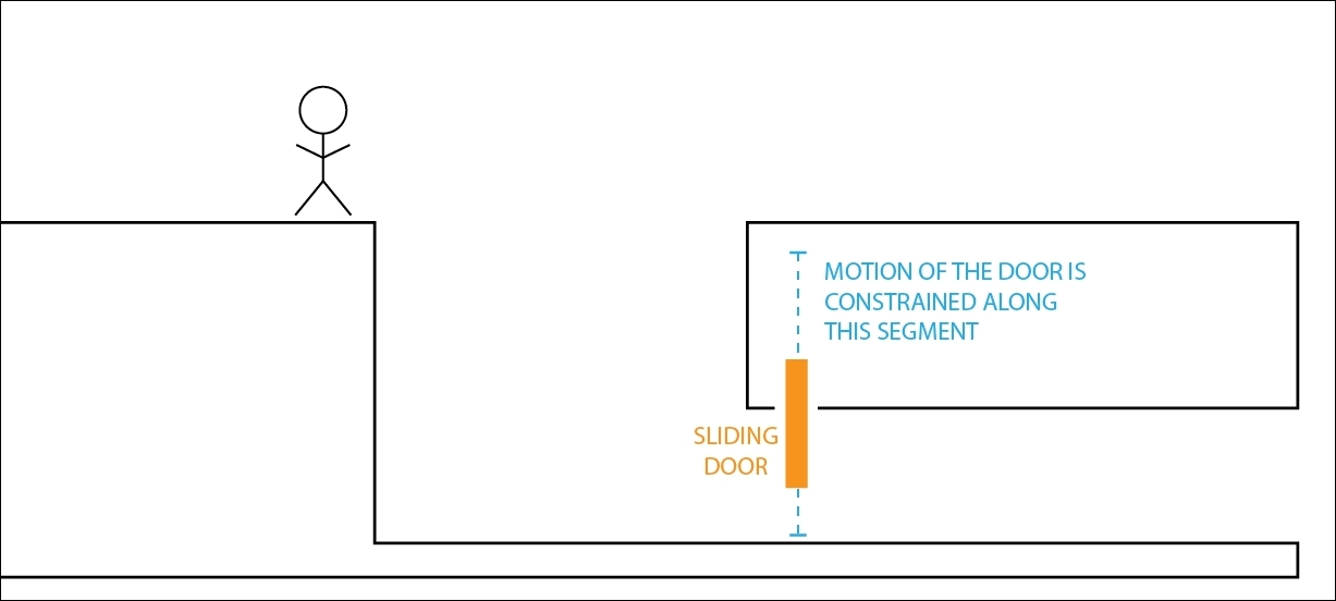
The sliding door in the diagram is constrained along a segment
As the name suggests, this is a pure spring joint 2D. It actually simulates a spring connected between the two rigidbodies, or a rigidbody and a fixed point. In fact, this joint gives you all the functionalities for a spring joint, and therefore you can simulate all the other pure (without a motor) spring-joints.
It appears like the following in the Inspector:
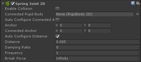
In addition to the parameters we have seen in the last section, the Spring Joint 2D has the following options:
- Distance: This specifies the distance that the two rigidbodies (or the rigidbody and the fixed point) should keep. You can imagine it also like the length of the spring in its rest position, which means the length of the spring when no forces are applied on it.
- Damping Ratio: This specifies how much you want to suppress the motion of the spring. Its value ranges from 0 to 1. Lower values mean a movable spring, higher values mean a stiff spring. If it is set to 1, the spring is not movable.
- Frequency: This specifies the frequency at which the spring oscillates while the objects are approaching the separation distance (which is the length of the spring in the rest position) specified in the Distance variable (measured in cycles per second). It ranges from 0 to 1,000,000. The higher the value, the stiffer the spring will be.
Whenever you need to place a spring in your game, this is the right joint. So, an example could be a physically realistic Launchpad, which you need to compress the spring, so as to let it have a boost in your jump. However, you don't need necessarily to think of this joint as a normal spring. In fact, you can bring this joint to the limits (such as a very stiff spring). As such, you are able to create other behaviours that in reality don't have a spring, but in the game they look nice when connected by a spring. Have you ever played Rayman? The character has its body parts separated, but they still move together in a coherent way in the game. If you are planning to create a similar character, the spring joint can be a valid solution to link the body parts in a realistic way. Here is an image of Rayman:

Image of Rayman. As you can see, the character doesn't have legs or arms, but has hands and feet. In your game, you can attach them to the chest through a Spring Joint.
The Target Joint 2D is a particular spring-type joint that, instead of having a second rigidbody, has a target. The aim is to keep the rigidbody where the component is attached at a certain distance from the target. It only applies a linear force; thus no torque is given to the rigidbody.
It appears like this in the Inspector:
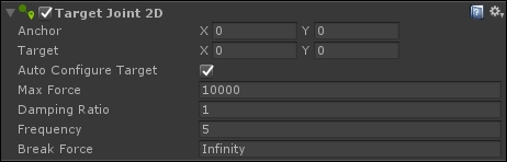
Since this component doesn't have a second rigidbody, there are some variables that allow you to specify the target:
- Anchor: Defined in local coordinates, with respect to the rigidbody, where the joint is attached on the rigidbody.
- Target: Defined in local coordinates, with respect to the rigidbody, where the other end of the joint tries to move.
- Auto Configure Target: When checked, it sets the Target to the current position of the rigidbody, which is useful when our rigidbody is moved around, maybe driven by other forces. Furthermore, when this option is selected, the Target changes as you move the rigidbody; on the contrary, it won't if the option is not selected.
Moreover, it is possible to control the characteristic of the spring with the usual parameters:
- Max Force: This specifies the maximum force that the joint can use on the rigidbody
- Damping Ratio: This specifies how much the motion of the spring is suppressed (refer to either the Spring 2D Joint or Fixed 2D Joint section for more details)
- Frequency: This specifies the frequency of the spring (refer to either the Spring 2D Joint or Fixed 2D Joint section for more details)
An example of the use of this joint is when the player needs to drag objects with the mouse. In this scenario, you can set the target of the object dragged to the cursor, so it will follow the cursor, without having a rigid movement (as if we would set frame after frame the position of the object to the mouse coordinates). Moreover, you can use the Anchor to specify where the object should be attached. For instance, if the player started to drag from a corner of the object, you can set the Anchor to be there, and as a result, the object will hang from that point.
The Wheel Joint 2D is a combination of a spring and motor kind of joint, and it has a very specific usage. As the name suggests, it simulates the constraint that a wheel can impose on a body. In particular, it can rotate the wheel with a motor (the wheel moves) and simulate suspensions with a spring.
More specifically, the joint applies a linear force to both connected rigid bodies to keep them on the line, an angular motor to rotate them on the line, and a spring to simulate the wheel suspension.
It appears like the following in the Inspector:
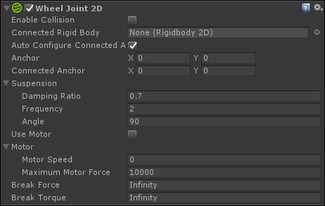
As you can see from the preceding screenshot, the parameters are divided into Suspension, which defines a spring, and a motor. Both use the same parameters we have already seen respectively for springs (with the exception of Angle) and motors.
The suspension is defined by the following:
- Angle: This specifies the angle (in degrees in world coordinates) where the suspension happens. By default, it is set to
90degrees, which means the suspension will happen upwards, as usually happens for a car (the body of the car is on top of the wheels, so the direction of the suspension is along the positive y-axis, which means 90 degrees) as shown in the following diagram: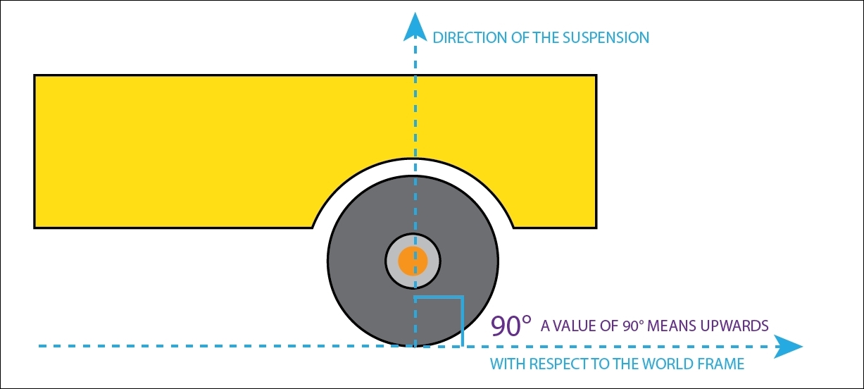
In this diagram, we can see the the angle of the suspension for the wheel of the car is at 90 degrees, which means upwards in the game world. This is the default value. Imagine you want to have a car that is able to run on the ceiling thanks to magnetic wheels; you may consider changing the angle of the suspension. In the case of the ceiling, it is the opposite of the normal situation, so the angle will be 270 degrees.
- Damping Ratio: This specifies how much the motion of the spring is suppressed (refer to either the Spring 2D Joint or Fixed 2D Joint section for more details).
- Frequency: This specifies the frequency of the spring (refer to either the Spring 2D Joint or Fixed 2D Joint section for more details).
The motor is defined by:
- Motor Speed: This specifies the speed that the motor should achieve on the wheel
- Max Motor Force: This specifies the maximum force that the motor can apply on the wheel in order to achieve Motor Speed on the wheel
Needless to tell you which is the most common usage of this joint. Every time in your game you have a wheel and it needs to move in a realistic manner, this joint is the deal for you.