
Chapter 2
Ablation
Abstract
This chapter describes the phenomenon ablation and its mechanisms, as well as its importance in aerospace applications. An illustrative model is analyzed, and the important physical parameters are identified.
Keywords
Ablation; Ablative material; Heat balance; Integral method; Pyrolysis; Unsteady heat conduction
2.1. Introduction
In aerospace design, ablation is used to both cool and protect mechanical parts that would otherwise be damaged by extremely high temperatures. Examples are heat shields for spacecraft, satellites, and missiles entering a planetary atmosphere from space and cooling of rocket engine nozzles. Basically, ablative material is designed to slowly burn away in a controlled manner, so that heat can be removed from the spacecraft by the gases generated by ablation, whereas the remaining solid material insulates the spacecraft from superheated gases. There has been an entire branch of spaceflight research involving the search for new fireproof materials to achieve the best ablative performance. Such a function is critical to protect the spacecraft occupants from otherwise excessive heat loading. The physical phenomena associated with ablation heat transfer depend on the application, but most involve in-depth material pyrolysis (charring) and thermochemical surface ablation. In numerical modeling, it is required to solve an energy equation, including effects of pyrolysis on a domain that changes as the surface ablates. Fig. 2.1 gives a general view of the ablation process and the involved mechanisms. As the material is heated, one or more components of the original composite material pyrolyze and yield a pyrolysis gas and a porous residue. The pyrolysis gas percolates away from the pyrolysis zone. The residue is often a carbonaceous char. The solution procedure is in principle a transient heat conduction calculation coupled to a pyrolysis rate calculation and subject to boundary conditions from the flow field.
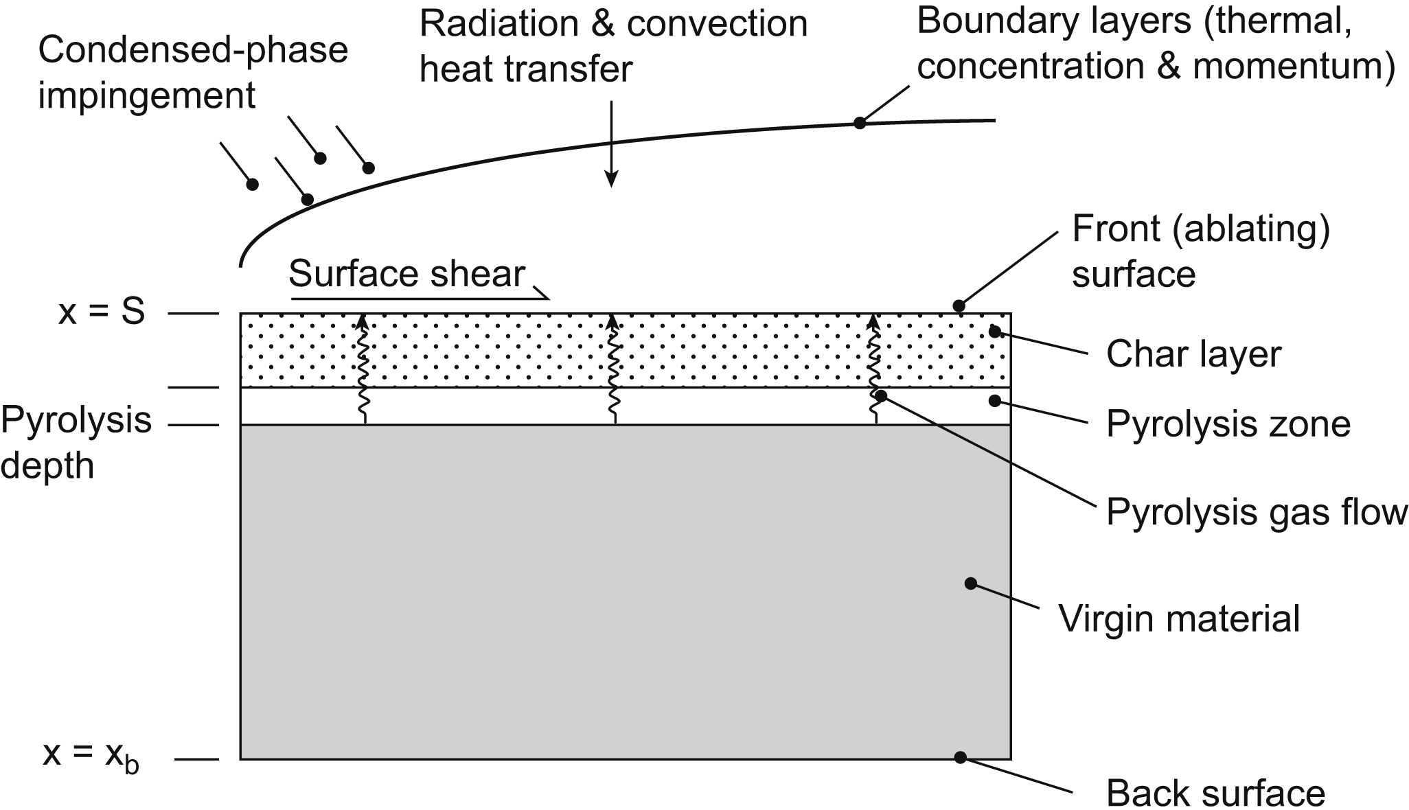
In terms of heat transfer, the following mechanisms are involved: (a) convection in the boundary layer, which gives rise to the main thermal load; (b) radiation; and (c) conduction in the virgin material. In addition, resin decomposition and fiber decomposition may occur. In the boundary layer, shocks may appear, and in some cases, there may be combustion.
Ablation is affected by the freestream conditions, the geometry of the reentry body, and the surface material. The vehicles range from blunt configurations, such as spacecraft, to slender sphere-cone projectiles. At low heating values, ablators of Teflon are used, whereas at high heat loads, graphites and carbon-based materials are used. The most common ablative materials are composites, i.e., materials consisting of a high-melting-point matrix and an organic binder. The matrix might be glass, asbestos, carbon, or polymer fibers braided in various ways. A honeycomb structure filled with a mixture of organic and inorganic substances and with high insulating characteristics can be used. Advances in chemistry and materials technology extend the possibilities of selecting improved ablative materials.
Also surface movement occurs by, e.g., material spallation. Various methods exist to solve the moving boundary problems, commonly referred to as the Stefan problems. Basically two methods are considered: the front-tracking methods and the front-fixing methods. With the front-tracking methods, the ablating surface (the front) is tracked as it moves into the material.
2.2. An Illustrative Example of Ablation
In this section a simplified model of ablation is presented. Basically a transient heat conduction analysis is presented. The transient thermal response of the material exposed to a high-energy environment is important knowledge in the design of heat shields for reentry vehicles. The surface of a semi-infinite solid is heated by applying a constant heat flux q0 (caused by frictional or aerodynamic heating) as shown in Fig. 2.2.
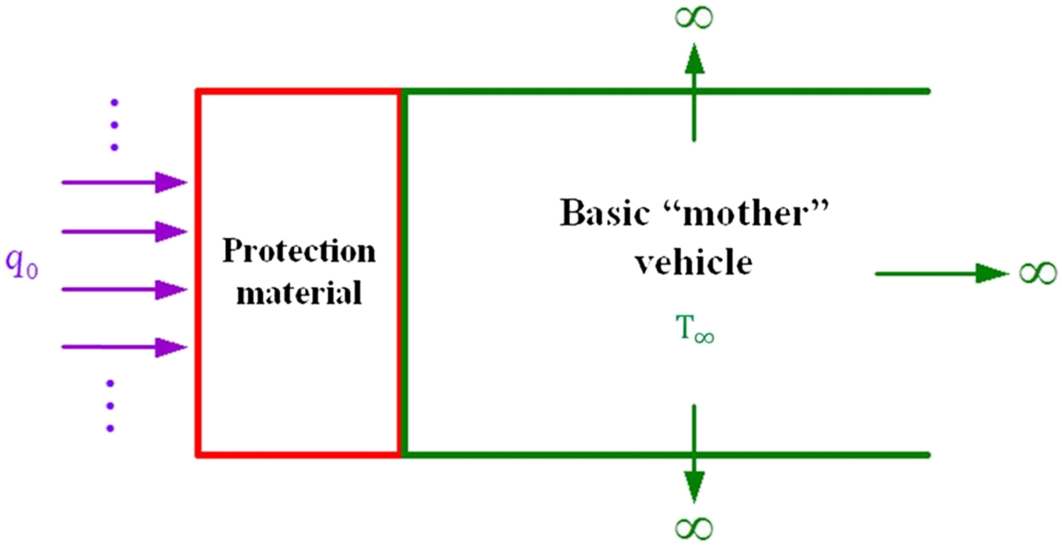
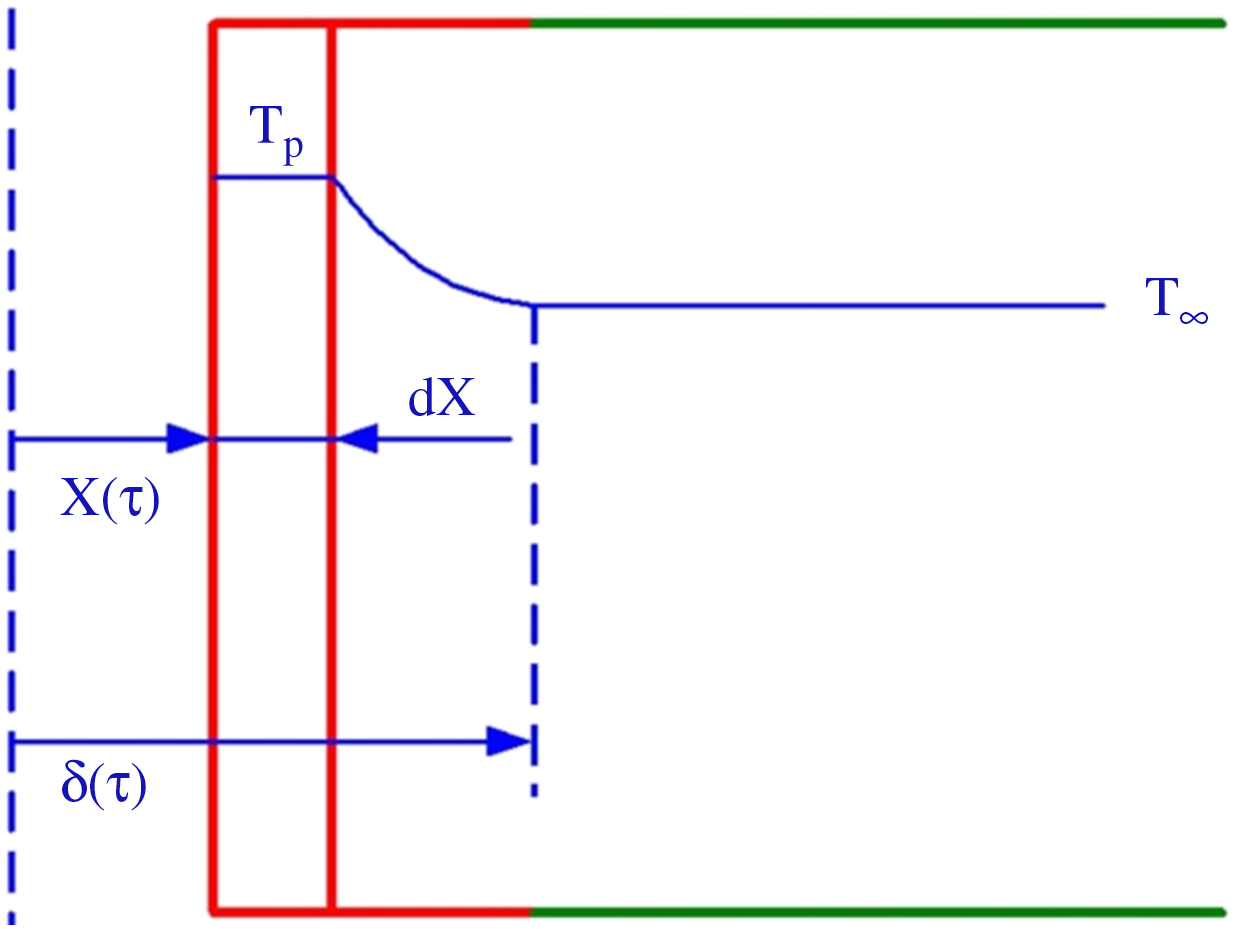
At time τ = 0 the surface temperature has risen to the melting temperature Tp and phase change is initiated. The melted material (liquid) formed is completely removed by the aerodynamic forces. In this case the surface recedes with time but the surface temperature remains constant at the phase change temperature. A temperature distribution exists only in the remaining solid as conjectured in Fig. 2.3.
At a certain time the solid surface is located at x = X(τ). The temperature variation in the solid material penetrates to a depth x = δ(τ). The temperature of the solid at far distances, x > δ(τ), from the surface is kept at the constant initial temperature T∞.
Introduce θ(x, τ) = T − T∞, which implies that θ(X, τ) = Tp − T∞ = θP.
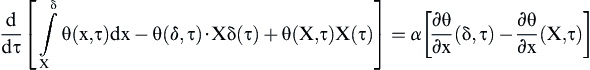
The one-dimensional unsteady heat conduction is then governed by
![]() (2.1)
(2.1)
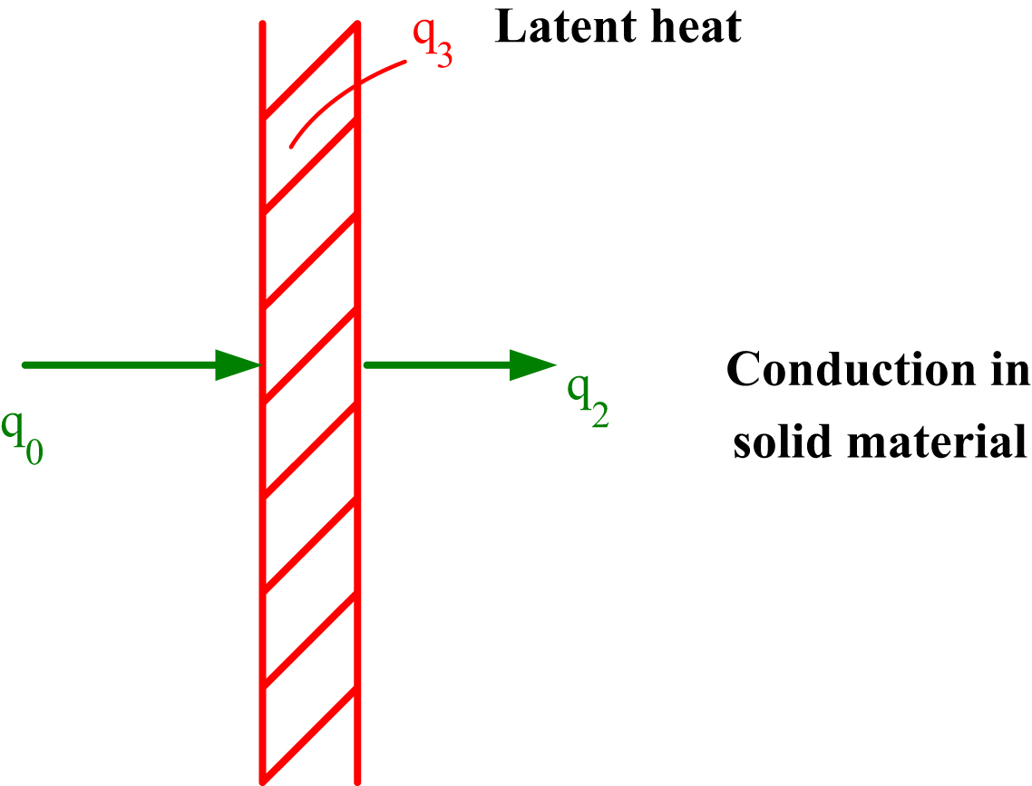
In Fig. 2.4 the heat balance at the interface is presented.
The thermal balance at the interface can be expressed as below:
![]() (2.2a)
(2.2a)
![]() (2.2b)
(2.2b)
The solution of Eq. (2.1) can be found by some standard procedures but here the integrated form is used. Details are given below.
The integrated form of Eq. (2.1) can be written as
 (2.3)
(2.3)
A second-order polynomial temperature profile is assumed as
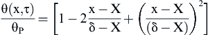 (2.4)
(2.4)
With the conditions θ(δ,τ) = 0 and θ(X,τ) = θP.
By combining the interface heat balance Eq. (2.2) with Eq. (2.3) and the assumed temperature profile Eq. (2.4), one obtains
![]() (2.5)
(2.5)
Further combination of the equations gives
![]() (2.6)
(2.6)
Eqs. (2.5) and (2.6) are simultaneous equations, making the solutions of X(τ) and δ − X possible. The initial condition for X is X(0) = 0. The initial condition for δ(τ), the specification for δ when the surface reaches the melting temperature TP, can be obtained from solutions of a semi-infinite solid exposed to a time varying surface heat flux by the equations (see, e.g., Ref. [1])
![]()
which gives the value of δ(τ) if a parabolic temperature profile is assumed, and
![]()
which gives the specification for the surface temperature as a result of a constant heat flux input q0.
Using the above equations the value of δ(τP) when the surface temperature reaches θP may be calculated as
![]() (2.7)
(2.7)
which is the remaining required initial condition.
Eqs. (2.5) and (2.6) have a steady-state solution if dX/dτ = A is a constant. Thus from Eq. (2.6), the value of δ—X must be constant, and then Eq. (2.5) gives
![]() (2.8)
(2.8)
![]() (2.9)
(2.9)
where
![]()
![]() (2.10)
(2.10)
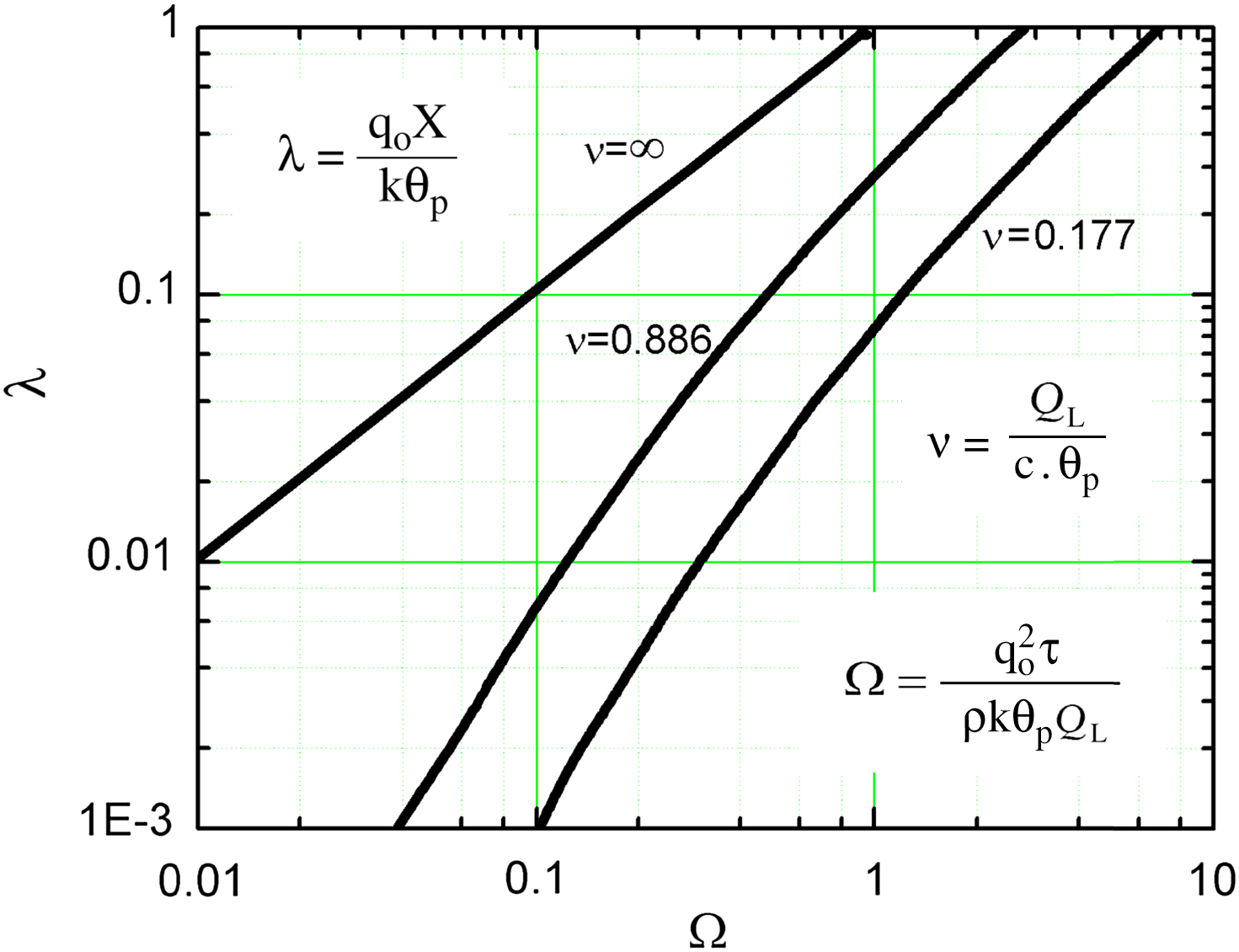
where λ =  .
.
The results above are depicted in Fig. 2.5. It presents, in dimensionless form, the melt-line location versus time, and the parametric influence of the variable ν introduced as ν = QL/(c·θP) is also clearly depicted.
2.3. Additional Information
Other simplified analyses have been presented by Han [3] and Holman [4]. In the analyses, it was assumed that a steady-state situation is attained and that the surface ablates at a constant rate.
Problems related to a melting solid for a variety of other boundary conditions have been presented in the literature. For instance, vaporization at the surface and aerodynamic heating by thermal radiation have been considered. Murray and Russell [5] presented a method for coupled aeroheating and ablation for missile configurations. Surface temperature and transient heat conduction calculations were carried out. The heat transfer coefficient was assumed to follow a known time function. The calculation method was verified against the flight test data.
In Ref. [6], a method of thermal protection for transatmospheric vehicles exposed to high heating rates was introduced. The method involved combined radiation, ablation, and transpiration cooling. By placing an ablative material behind an outer shield that is of fixed shape and is porous, the effectiveness of the transpiration cooling was maintained, while retaining the simplicity of a passive mechanism. In the analysis, a simplified one-dimensional approach was used to derive the governing equations, which were reduced to a nondimensional form. In doing so, two parameters appeared to control the thermal protection effectiveness and ablation. The parameters are related to the thermal properties of the ablative and shield materials. The ablative material was also required to absorb a sufficient amount of thermal energy (related to the heat of ablation or vaporization) to keep the outer shield temperature below a specified value. A low vaporization temperature was found favorable to allow for the release of gaseous products and take advantage of the transpiration mechanism completely. Four ablative materials were considered and it was found that one material with thermal properties similar to those of Teflon behaved very well.
A relatively old report [7] presented a qualitative review of fundamental relationships involved in engineering and aerodynamic heating. The report included aerodynamic heating, boundary layer mass transfer, general thermal protection, ablative materials, and the structural aspects of ablation. In particular the general properties of charring ablators were discussed.
A comprehensive study of thermal protection systems was presented in a doctoral thesis [8], in which most mechanisms of the ablation phenomenon were treated in detail but mainly by computational fluid dynamics (CFD)-based methods.
A simplified analysis, similar to the one presented in this chapter, of ablation in cylindrical bodies was presented in Ref. [9]. The so-called general integral transform technique (GITT) was used to analyze the unsteady heat conduction, but with a transient surface heat flux.
..................Content has been hidden....................
You can't read the all page of ebook, please click here login for view all page.