


Remote Direct Memory Access over Converged Ethernet setup
In general, there are two different ways to deploy an RDMA over Converged Ethernet (RoCE) environment. The simplest way is to have one adapter port per node that is connected to the network that uses a TCP daemon for communication and uses the same port for RoCE traffic concurrently.
The more complex but powerful and flexible configuration is to have multiple ports that are connected to the network that use one port for TCP daemon communication and Remote Direct Memory Access (RDMA) in parallel simultaneously and all the other ports for only RDMA and RoCE traffic. With this configuration, a node’s bandwidth capabilities can scale out nearly linearly.
Optionally, Mellanox and IBM have developed an option to configure a network bond, which consists of two ports from the same adapter to protect against cable, port, or switch issues.
For best performance results and reliability, it is a best practice to have a network that is configured to be “lossless”. This RoCE environment is summarized in this chapter.
3.1 Network requirements
For running RoCE, the best performance that you can get is when the network is configured as a “lossless” fabric. Depending on the vendor, components, and the topology, this “lossless” requirement can lead to a complex configuration that is out of scope of this document. However, you can find an example configuration in Appendix A, “Mellanox switch configuration for Remote Direct Memory Access over Converged Ethernet” on page 37.
To have a lossless fabric configured, consult your network administration and provider. For more information, see Recommended Network Configuration Examples for RoCE Deployment.
Make sure that all the nodes in your cluster have the most recent Mellanox OpenFabrics Enterprise Distribution (MOFED) driver that is installed properly. The IBM Elastic Storage System (ESS) I/O server nodes are maintained by IBM Spectrum Scale deployment. You can check the installed version by running the ofed_info -s command:
[root@c902ess1-gssio1 network-scripts]# ofed_info -s
MLNX_OFED_LINUX-x.x.x.x.x
[root@c902ess1-gssio1 network-scripts]#
The minimum required level for OpenFabrics Enterprise Distribution (OFED) is documented within the release notes of the ESS.
It is a best practice that the IBM Spectrum Scale client nodes run the same MOFED level as the Network Shared Disk (NSD) or ESS.
However, in many projects and environments, it is a hard to maintain all nodes with the same MOFED level. We have seen successful examples in the market where the client nodes running the OFED are distributed within the operating system (OS), which more convenient for operating and maintaining the client clusters. However, in cases of issues and network glitches, those configurations can cause unexpected failures.
3.2 Network topology
The term host in this chapter is used for an endpoint in the network. It can be an
IBM Spectrum Scale client machine or an ESS or NSD server machine.
IBM Spectrum Scale client machine or an ESS or NSD server machine.
A host’s configuration depends on the number of network ports that are used or needed. The number of network ports that a node should be connected to in the network depends on the expected bandwidth or on the number of different networks the host must have access to in other environments. The number of ports also is determined by high availability (HA) requirements.
In TCP environments, scaling bandwidth with multiple ports is acquired by using bonding network ports, which are also known as link aggregation. But, bonding has some challenging side effects, and it makes the deployment more complex from the network perspective.
Bonding is a commonly used technology in data centers to better load balance traffic in the network. However, bonding does not help single-socket network traffic to use more than one cable. Furthermore, another significant drawback of bonding is that the selection of the network path is hard to predict or cannot be controlled from the application layer.
The biggest negative side effect of using network bonds is that Inter-switch Links (ISLs) between switches are used, which adds more network hops and latency.
So, when scaling bandwidth over multiple ports is needed, RoCE is the better option because it saves many system and network resources by using RDMA because the application directly accesses the data through the network without using the OS’s resources. Independently from using link aggregation, when you use IBM Spectrum Scale, the generic rule is to have exactly one IP interface that is connected to the IP range for the mmfs daemon-to-daemon communication. A best practice network topology with bonding and RoCE looks like Figure 3-1.
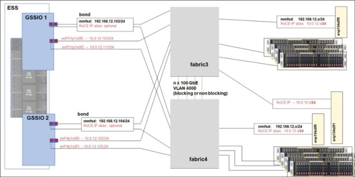
Figure 3-1 Network topology with bonding for mmfsd communication
When using a bond, you must set the Link Aggregation Control Protocol (LACP) link aggregation in the network.
Alternatively, by using ESS building blocks, you can also rely on higher HA layers in
IBM Spectrum Scale like NSD and Recovery-Group server failover, so you might consider skipping bonds in your topology to make the network setup less complex. For improved performance and a less complex setup, a best practice is to use a configuration without bonding.
IBM Spectrum Scale like NSD and Recovery-Group server failover, so you might consider skipping bonds in your topology to make the network setup less complex. For improved performance and a less complex setup, a best practice is to use a configuration without bonding.
An example for a configuration without bonding looks like Figure 3-2.

Figure 3-2 Network topology without bonding
In a network topology without bonding, you must have one IP address per network port. On the adapter that has the mmfsd IP address configured, you do not need an extra RoCE IP address or alias if all the nodes in your cluster can communicate to this mmfsd IP address. You can configure as many aliases as the OS version supports. You need one IP per adapter, and RoCE also can use the existing IP that also is used for TCP/IP traffic.
By running a configuration without bonds in the IBM Spectrum Scale configuration, you can enhance the whole configuration by adding fabric numbers. Therefore, traffic on the ISLs can be avoided, and performance can be optimized.
|
Note: The adapters in a RoCE-enabled environment can run TCP/IP traffic and RDMA traffic simultaneously.
|
3.3 Connection Manager and Subnet Manager
If you operate an InfiniBand network, the Subnet Manager (SM) often is used. The SM is a real service, running mostly on the switches, the hosts, or both. The SM discovers and configures all the devices in an InfiniBand fabric. When using the SM in an InfiniBand fabric, you do not have to configure the IP address on the hosts or switches.
The Connection Manager (CM) is a special method to identify and set up the connections between communication partners. It can be used for Ethernet and InfiniBand, it is part of the OFED, and it provides an RDMA transport-neutral interface for establishing connections. It is not a central component (that is, running on the switches like SM), but a component that runs on each individual node. The API concepts are based on sockets, but they are adapted for queue pair (QP) based semantics. To use the CM, you must have IP addresses that are configured.
For RDMA over Ethernet, using CM is mandatory. For InfiniBand, CM is an optional alternative to SM.
InfiniBand and Ethernet can be used simultaneously. Ethernet-based RDMA communication always requires an IP address to work. For those nodes that are connected to both fabrics, you must configure an IP address on all adapter ports, including all InfiniBand ports.
Make sure that a clear separation of IP subnets is configured to the different adapters and fabrics because the adapter must be able to communicate through an IP address to allow IBV verbs to establish connections through CM. You cannot create connections between Ethernet ports and InfiniBand ports for RDMA. Even though there are special routing scenarios to make these cross-fabric connections work, they work only for a TCP/IP connection.
However, an IBM Spectrum Scale node can create RDMA connections over InfiniBand to cluster A while having RoCE connections to the nodes of cluster B.
|
Note: When using CM, all nodes in the InfiniBand fabric, which must communicate with each other, need an IP address on their InfiniBand interfaces to establish connections. This situation is true for each node with CM configured, even if SM is still running on the fabric.
|
3.4 Host configuration
In general, we distinguish between a client and a server in an IBM Spectrum Scale environment. The recommendations in this section apply to both types of hosts.
To configure the host adapters in our examples, we decide whether we want to have the IP interface protected by link aggregation or use a regular IP interface.
If bonding is used, RDMA restrictions mean that you can bond only two ports in one bond, and both of those ports must be on the same physical RoCE adapter. So, you get HA protection of the IP address.
All the other adapters of the I/O servers appear as individual devices.
Figure 3-1 on page 7 shows the network topology with bonding for mmfsd communication.
|
Note: If you use bonding, the two ports in the bond must have the switch site configured with LACP (Multi-Chassis Link Aggregation (MLAG)).
|
In our examples, we have two dual-port adapters in the ESS I/O servers. The output of the commands on the ESS I/O servers looks like the following output:
[root@ess5kio1 ~]# lspci | grep Mell
0000:01:00.0 Ethernet controller: Mellanox Technologies MT28800 Family [ConnectX-5 Ex]
0000:01:00.1 Ethernet controller: Mellanox Technologies MT28800 Family [ConnectX-5 Ex]
0033:01:00.0 Ethernet controller: Mellanox Technologies MT28800 Family [ConnectX-5 Ex]
0033:01:00.1 Ethernet controller: Mellanox Technologies MT28800 Family [ConnectX-5 Ex]
[root@ess5kio1 ~]# ibdev2netdev
mlx5_0 port 1 ==> enp1s0f0 (Up)
mlx5_1 port 1 ==> enp1s0f1 (Up)
mlx5_2 port 1 ==> enP51p1s0f0 (Up)
mlx5_3 port 1 ==> enP51p1s0f1 (Up)
[root@ess5kio1 ~]#
The clients that we are using have only one adapter, and we use only one port per client:
[root@fscc-sr650-13 ]# lspci | grep Mell
86:00.0 Ethernet controller: Mellanox Technologies MT27700 Family [ConnectX-4]
86:00.1 Ethernet controller: Mellanox Technologies MT27700 Family [ConnectX-4]
[root@fscc-sr650-13 ]# ibdev2netdev
mlx5_0 port 1 ==> enp134s0f0 (Up)
mlx5_1 port 1 ==> enp134s0f1 (Down)
[root@fscc-sr650-13 ]#
3.4.1 Operating system setting for AMD hardware
When enabling InfiniBand on AMD64 hardware, iommu=soft might be required in the grub boot options to permit allocations greater than 1 GB to the VERBS RDMA device, which might impact performance and CPU utilization.
3.4.2 Optional: Ring buffer and other adapter settings
Depending on the hardware, server type, and models of the client/server setup, you might want to adjust the adapter settings. On ESS, you can use the default settings from the deployment procedure.
The clients that we use in our example are fast enough with the default settings. We reach full wire speed with the default adapter settings, so we keep the defaults on the clients.
However, if you do not see the expected network performance, you might want to change the adapter settings in your environment.
If you do not get the wire speed that you want, here are some approaches.
•Try to set the rx and tx buffers a bit higher, step by step. If you go from 1024 to 8192 in one step, you might impact running workloads, and depending on the available free memory resources, you might crash the system.
•When you have your optimized setup, configure an udev rule to make it automatically effective.
•To take advantage of the network adapter capabilities, check the maximum values for tx and rx buffers on the adapter.
Here is an example of checking the maximum values for TX and RX buffers:
[root@lbs2gssio1 ~]# ethtool -g enP4p1s0f0
Ring parameters for enP4p1s0f0:
Pre-set maximums:
RX: 8192
RX Mini: 0
RX Jumbo: 0
TX: 8192
Current hardware settings:
RX: 8192
RX Mini: 0
RX Jumbo: 0
TX: 8192
As a best practice, create persistent udev rules to adjust the settings automatically. An example of a valid udev rule follows:
# cat /etc/udev/rules.d/99-ibm-custom.rules
KERNEL=="ens5f0", RUN+="/sbin/ip link set %k txqueuelen 10000" , RUN+="/sbin/ip link set %k txqueuelen 10000", RUN+="/sbin/ethtool -G %k rx 8192" , RUN+="/sbin/ethtool -G %k tx 8192"
# a more generic one
# cat /etc/udev/rules.d/99-ibm-custom.rules
KERNEL=="enp*", RUN+="/sbin/ip link set %k txqueuelen 10000" , RUN+="/sbin/ip link set %k txqueuelen 10000", RUN+="/sbin/ethtool -G %k rx 8192" , RUN+="/sbin/ethtool -G %k tx 8192"
KERNEL=="enP*", RUN+="/sbin/ip link set %k txqueuelen 10000" , RUN+="/sbin/ip link set %k txqueuelen 10000", RUN+="/sbin/ethtool -G %k rx 8192" , RUN+="/sbin/ethtool -G %k tx 8192"
# active by
udevadm control --reload-rules
udevadm trigger
3.4.3 Maximum Transmission Unit consideration
RDMA was introduced on InfiniBand networks. RDMA over InfiniBand supports Maximum Transmission Unit (MTU) sizes of 256 - 4096 bytes.
On Ethernet, you can configure larger MTUs. As a best practice, adjust the MTU so that you use jumbo frames, which are 9000 bytes. Adjust this setting on all adapters and all nodes in your clusters.
If you must communicate with outside nodes in remote networks and you cannot be sure that the path through the network supports MTU 9000 end-to-end, make sure that you have MTU Path discovery enabled. MTU path discovery is enabled by default on Linux. Do not forget to set MTU size also on all the switches in the fabric to be able to benefit from jumbo frames.
You can check MTU path discovery by using the following command:
[root@fscc-sr650-18 ~]# cat /proc/sys/net/ipv4/ip_no_pmtu_disc
0
[root@fscc-sr650-18 ~]#
3.4.4 Firewall
There is no special port that is defined for RoCE traffic. However, you need a working TCP/IP connection between both ends. By using RoCE, you aim for high performance with low latency, so using a network where firewalls are in place is not recommended.
An IBM Spectrum Scale cluster is a trusted environment. It is common practice to put the RDMA interfaces into a trusted zone, as shown in the following command:
# firewall-cmd --permanent --zone=trusted --add-interface=ens5f0
3.4.5 Bond configuration
For RoCE V2 to work correctly, all interfaces need an IPv6 local link address and an IPv4 address.
Configuring bond interfaces is optional and not needed to run RoCE. If you want to have your IP interfaces protected against port failures, follow the procedure in this section.
To configure the bond on Red Hat Enterprise Linux (RHEL), use the nmcli utility. For more information about this task, see Configuring Network Bonding.
|
Bonding issues:
A bonded interface protects against port and cable failures. However, when running RDMA, all ports of the bonded interface must be on the same physical PCI adapter. So, an adapter failure is not covered by this configuration. Furthermore, creating bonds over multiple switches makes an MLAG configuration mandatory in the network, which can cause unbalanced network utilization in the fabric.
Another significant reason not to use bonding when using RoCE is the better performance that you get when you do not use a bond. Using the bond offers only one virtual port for RDMA. In some performance-optimized environments, RDMA ports in IBM Spectrum Scale can be sorted to different fabrics by referring to isolated traffic to avoid ISL bottlenecks. When you use a bond, you cannot predict the traffic, so RDMA fabrics are hard to use or will cause ISL traffic.
|
Example 3-1 shows an example of configuring a bond on RHEL by using the nmcli utility.
Example 3-1 Configuring a bond on RHEL by using the nmcli utility
nmcli connection add type bond con-name bond0 ifname bond0 bond.options "mode=802.3ad,miimon=1000,xmit_hash_policy=layer3+4"
nmcli con add type ethernet slave-type bond con-name bond0-p1 ifname enp1s0f0 master bond0
nmcli con add type ethernet slave-type bond con-name bond0-p2 ifname enp1s0f1 master bond0
nmcli connection modify bond0 ipv4.addresses '192.168.12.102/24'
nmcli con mod bond0 ipv4.method static
nmcli con mod bond0 ipv6.addr-gen-mode eui64
nmcli con mod bond0-p1 802-3-ethernet.mtu 9000
nmcli con mod bond0-p1 mtu 9000
nmcli con mod bond0-p2 802-3-ethernet.mtu 9000
nmcli con mod bond0-p2 mtu 9000
nmcli con mod bond0 mtu 9000
An appropriate port channel in the network or switch (that uses LACP or MLAG) must be configured.
For RoCE V2 to work correctly, the interfaces need an IPv6 local link address and an IPv4 address. Make sure that the IPv6 local link address is set correctly, which is highlighted in bold in Example 3-1.
Make the changes effective and start the interface by running the following command:
[root@lbs2gssio1 ~]# # nmcli connection up bond0
[root@lbs2gssio1 ~]#
After activating the bond, the MOFED driver changes the device configuration. Instead of seeing both RDMA devices for the adapter with the bonded ports, the mlx5_bond_0 device is created. The driver may take up to 5 seconds to reconfigure the devices.
[root@ess5kio1 ~]# ibdev2netdev
mlx5_2 port 1 ==> enP51p1s0f0 (Up)
mlx5_3 port 1 ==> enP51p1s0f1 (Up)
mlx5_bond_0 port 1 ==> bond0 (Up)
[root@ess5kio1 ~]#
As a best practice, protect only the mmfsd IP address with a bond. All other interfaces can be used without a bond. For more configuration examples, see 3.4.6, “Regular IP interface configuration” on page 13. You can run a similar configuration on the other (ESS) nodes and on the clients.
3.4.6 Regular IP interface configuration
For RoCE V2 to work correctly in a regular IP interface, all interfaces need an IPv6 local link address and an IPv4 address. Configure all interfaces where you intend to use RoCE communication, as shown in Figure 3-3.

Figure 3-3 Topology without bonding
As highlighted in bold in Figure 3-3, make sure that only one IP interface has an IP address for the mmfs daemon communication. All other interfaces must be on a different subnet. Usually, we start configuring the NSD server and then proceed with the clients.
Use the nmcli utility to configure your environment, as shown in Example 3-2.
Example 3-2 Configuring the environment with the nmcli utility
#####################################################
#
# ESS5000 IOservers IO1
#
ifdown enp1s0f0
nmcli con del enp1s0f0
nmcli con add type 802-3-ethernet ifname enp1s0f0 connection.interface-name
enp1s0f0 connection.id enp1s0f0
nmcli con mod enp1s0f0 ipv4.addresses 192.168.12.102/24
nmcli con mod enp1s0f0 ipv4.method static
nmcli con mod enp1s0f0 connection.autoconnect yes
nmcli con mod enp1s0f0 802-3-ethernet.mtu 9000
nmcli con mod enp1s0f0 ipv6.addr-gen-mode eui64
ifup enp1s0f0
ifdown enp1s0f1
nmcli con del enp1s0f1
nmcli con add type 802-3-ethernet ifname enp1s0f1 connection.interface-name enp1s0f1
connection.id enp1s0f1
nmcli con mod enp1s0f1 ipv4.addresses 10.0.12.112/24
nmcli con mod enp1s0f1 ipv4.method static
nmcli con mod enp1s0f1 connection.autoconnect yes
nmcli con mod enp1s0f1 802-3-ethernet.mtu 9000
nmcli con mod enp1s0f1 ipv6.addr-gen-mode eui64
ifup enp1s0f1
ifdown enP51p1s0f0
nmcli con del enP51p1s0f0
nmcli con add type 802-3-ethernet ifname enP51p1s0f0 connection.interface-name enP51p1s0f0
connection.id enP51p1s0f0
nmcli con mod enP51p1s0f0 ipv4.addresses 10.0.12.103/24
nmcli con mod enP51p1s0f0 ipv4.method static
nmcli con mod enP51p1s0f0 connection.autoconnect yes
nmcli con mod enP51p1s0f0 802-3-ethernet.mtu 9000
nmcli con mod enP51p1s0f0 ipv6.addr-gen-mode eui64
ifup enP51p1s0f0
ifdown enP51p1s0f1
nmcli con del enP51p1s0f1
nmcli con add type 802-3-ethernet ifname enP51p1s0f1 connection.interface-name enP51p1s0f1
connection.id enP51p1s0f1
nmcli con mod enP51p1s0f1 ipv4.addresses 10.0.12.113/24
nmcli con mod enP51p1s0f1 ipv4.method static
nmcli con mod enP51p1s0f1 connection.autoconnect yes
nmcli con mod enP51p1s0f1 802-3-ethernet.mtu 9000
nmcli con mod enP51p1s0f1 ipv6.addr-gen-mode eui64
ifup enP51p1s0f1
Make sure that the IPv6 local link address is configured correctly by comparing the interface’s MAC address with the last fields in the IPv6 address:
6: enp1s0f0: <BROADCAST,MULTICAST,UP,LOWER_UP> mtu 9000 qdisc mq state UP group default qlen 1000
link/ether 0c:42:a1:d7:1a:e8 brd ff:ff:ff:ff:ff:ff
inet 10.0.12.102/24 brd 10.0.12.255 scope global noprefixroute enp1s0f0
valid_lft forever preferred_lft forever
inet 192.168.12.102/24 brd 192.168.12.255 scope global noprefixroute enp1s0f0
valid_lft forever preferred_lft forever
inet6 fe80::e42:a1ff:fed7:1ae8/64 scope link noprefixroute
valid_lft forever preferred_lft forever
For the I/O server, we have the final IPv4 configuration as shown in the following example:
[root@ess5kio1 ~]# ip -4 a | grep inet
inet 127.0.0.1/8 scope host lo
[...]
inet 10.0.12.102/24 brd 10.0.12.255 scope global noprefixroute enp1s0f0
inet 192.168.12.102/24 brd 192.168.12.255 scope global noprefixroute enp1s0f0
inet 10.0.12.112/24 brd 10.0.12.255 scope global noprefixroute enp1s0f1
inet 10.0.12.103/24 brd 10.0.12.255 scope global noprefixroute enP51p1s0f0
inet 10.0.12.113/24 brd 10.0.12.255 scope global noprefixroute enP51p1s0f1
On client machines, which have fewer interfaces than the servers, make sure that the IP interface has all the needed IP aliases to communicate to all server ports, as in the following example:
[root@ece-13 ~]# ip -4 a | grep inet
[...]
inet 192.168.12.13/24 brd 192.168.12.255 scope global noprefixroute enp134s0f0
inet 10.0.12.13/24 brd 10.0.12.255 scope global noprefixroute enp134s0f0
Regardless of whether you use a bonded or a regular interface, all clients must have an IP address to access the mmfsd daemons network. To enable the client node to connect with the RoCE interfaces to any other nodes with different IP ranges, use either a routing configuration in the network, or as it is demonstrated here in the example, add an IP alias to the interface because it is connected to the same physical network.
The client’s network configuration as is shown in the following example:
[root@fscc-sr650-13]# ip -4 a
1: lo: <LOOPBACK,UP,LOWER_UP> mtu 65536 qdisc noqueue state UNKNOWN group default qlen 1000
inet 127.0.0.1/8 scope host lo
valid_lft forever preferred_lft forever
[…]
6: enp134s0f0: <BROADCAST,MULTICAST,UP,LOWER_UP> mtu 9000 qdisc mq state UP group default qlen 1000
inet 192.168.12.13/24 brd 192.168.12.255 scope global noprefixroute enp134s0f0
valid_lft forever preferred_lft forever
inet 10.0.12.13/24 brd 10.0.12.255 scope global noprefixroute enp134s0f0
valid_lft forever preferred_lft forever
3.4.7 Routing configurations
In our example, the mmfsd communication runs in the 192.168.12.0/24 network. All other Mellanox cards interfaces are highlighted in red, shown in Figure 3-4, and they are configured to be in the subnet 10.0.12.x/24. All interfaces are intended to be used for RDMA communication, and only the IP addresses in the 192.168.12.0/24 network are used for TCP/IP communication, which are highlighted in bold in Figure 3-4.

Figure 3-4 Network topology without bonding
With current IBM Spectrum Scale releases, only one IP address per node is supported for TCP/IP communication to the mmfs daemon’s network.
To scale out over multiple ports, we use RoCE. Per the OFED standard, each RDMA interface must have an IP address to maintain the connection.
Because we want to use multiple interfaces, in theory we must configure multiple subnets, but this configuration is not practical for larger environments and technically not needed. We also can configure all the interfaces that we intend to use for RDMA into one interface that is separate from the mmfsd network and subnet.
A limitation of the Linux kernel is that multiple interfaces to the same subnets are challenging. You must consider answering ARP requests, selecting rules for outgoing IP traffic, and other items when you have more than one interface per subnet on a node. To solve those problems, you need to add special routing tables. You must specify only routing entries for each interface and all subnets where you have more than one interface to connect.
In our example, each I/O server node has four interfaces that are connected to the same physical network. For better administration, we assign a 10.0.12.xx/24 address to each interface, and we configure the mmfsd IP address on the network port, which is optional because we have a network topology without bonding.
For all interfaces pointing to the 10.0.12.x IP address, an extra routing entry is needed if you have more than one IP interface to the same subnet. If you have only one IP interface to a network, the necessary routing entry for the kernel is done automatically by the OS. With more that one IP interface to the same network, you must create special routes because the Linux kernel does not specifically tie IP addresses to MAC addresses by default. Any network interface controller (NIC) can respond to any ARP request for an IP address that belongs to the server. For RoCE to work correctly, we must make sure that the right interfaces answer connection requests. So, we must create multiple routing entries.
In our example, the clients have only one interface to the servers. The client's single interface has two IP address, one in the daemon network and one for the separated IP range, which can be referenced as a RoCE network. In this configuration, you can skip the optional IP alias for the RoCE network on the server side, which is marked as “optional” in Figure 3-4 on page 16.
If you use clients with multiple adapter ports, the same rule applies to the clients. The clients must have only one IP interface with a mmfsd IP address, but it can have one or many other extra interfaces within the separated IP range (RoCE). For those client interfaces to communicate to all interfaces on the server side, they must have a matching IP address. So, you must configure them as “optional” RoCE IP aliases on the interface with the mmfsd IP address.
To configure the routing, open the /etc/iproute2/rt_tables file and add one table per interface for all interfaces on the same subnet. In our example, the file contains four extra lines (bolded):
[root@c902ess1-gssio1 network-scripts]# cat/etc/iproute2/rt_tables
#
# reserved values
#
255 local
254 main
253 default
0 unspec
#
# local
#
#1 inr.ruhep
100 t1
101 t2
102 t3
103 t4
Alternatively, you can run the following commands:
echo "101 t1" >> /etc/iproute2/rt_tables
echo "102 t2" >> /etc/iproute2/rt_tables
echo "103 t3" >> /etc/iproute2/rt_tables
echo "104 t4" >> /etc/iproute2/rt_tables
Do not forget to do this task on each node where you have multiple interfaces to the same subnet configured, or distribute this file among your cluster nodes so that they have same configuration.
Routing entries in RHEL8.x
In RHEL8, the method to set the network configuration was changed in the OS. Setting those routing entries must be done by using the nmcli utility. Furthermore, the routing configuration files that were in earlier releases of RHEL 7.x in /etc/sysconfig/network.scripts/ are no longer present.
To create the routes in RHEL 8.x on the I/O servers, use the script that is shown in Example 3-3.
Example 3-3 Creating routes on I/O servers in RHEL 8.x
nmcli con modify enp1s0f0 +ipv4.routes "0.0.0.0/1 10.0.12.254 table=101, 128.0.0.0/1 10.0.12.254 table=101"
nmcli con modify enp1s0f0 +ipv4.routes "10.0.12.0/24 table=101 src=10.0.12.102"
nmcli con modify enp1s0f0 +ipv4.routing-rules "priority 32761 from 10.0.12.102 table 101"
ifdown enp1s0f0; ifup enp1s0f0
nmcli con modify enp1s0f1 +ipv4.routes "0.0.0.0/1 10.0.12.254 table=102, 128.0.0.0/1 10.0.12.254 table=102"
nmcli con modify enp1s0f1 +ipv4.routes "10.0.12.0/24 table=102 src=10.0.12.112"
nmcli con modify enp1s0f1 +ipv4.routing-rules "priority 32761 from 10.0.12.112 table 102"
ifdown enp1s0f1; ifup enp1s0f1
nmcli con modify enP51p1s0f0 +ipv4.routes "0.0.0.0/1 10.0.12.254 table=103, 128.0.0.0/1 10.0.12.254 table=103"
nmcli con modify enP51p1s0f0 +ipv4.routes "10.0.12.0/24 table=103 src=10.0.12.103"
nmcli con modify enP51p1s0f0 +ipv4.routing-rules "priority 32761 from 10.0.12.103 table 103"
ifdown enP51p1s0f0; ifup enP51p1s0f0
nmcli con modify enP51p1s0f1 +ipv4.routes "0.0.0.0/1 10.0.12.254 table=104, 128.0.0.0/1 10.0.12.254 table=104"
nmcli con modify enP51p1s0f1 +ipv4.routes "10.0.12.0/24 table=104 src=10.0.12.113"
nmcli con modify enP51p1s0f1 +ipv4.routing-rules "priority 32761 from 10.0.12.113 table 104"
ifdown enP51p1s0f1; ifup enP51p1s0f1
For a bond interface that has only the mmfsd network IP address, no route is needed because the IP address is the only IP interface into that network. If you prefer to have the optional “red” RoCE address as an extra alias, then a route for the “red” IP subnet also is needed.
In the first line of Example 3-3, a routing entry for one interface (here enp1s0f0) is generated for the routing table number 101. It is a default rule that starts from 0.0.0.0/1 and 128.0.0.0.1. The reason for this layout is that the nmcli utility does not support using 0.0.0.0/0 for the default gateway in the field ipv4.gateway. To work around this problem, the command creates separate routes for both the 0.0.0.0/1 and 128.0.0.0/1 subnets, which also cover the full IPv4 address space.
In the second line, we add the source IP address to be used for this route in the routing table number 101.
In the third line, we add the rule to use this routing table.
In the fourth line, we restart the interface to make the changes effective.
Verifying the routing table
After configuring the routing table, you might want to double check that your changes to the system are correct. To do so, run the ip command, as shown in Example 3-4.
Example 3-4 Double-checking your changes by using the ip command
[root@ess5kio1 ~]# ip r
default via xxxxxx dev enP1p8s0f1 proto static metric 101
[…]
10.0.12.0/24 dev enp1s0f0 proto kernel scope link src 10.0.12.102 metric 107
10.0.12.0/24 dev enp1s0f1 proto kernel scope link src 10.0.12.112 metric 108
10.0.12.0/24 dev enP51p1s0f0 proto kernel scope link src 10.0.12.103 metric 109
10.0.12.0/24 dev enP51p1s0f1 proto kernel scope link src 10.0.12.113 metric 110
[…]
192.168.12.0/24 dev enp1s0f0 proto kernel scope link src 192.168.12.102 metric 107
[…]
[root@ess5kio1 ~]# ip r show table t1
0.0.0.0/1 via 10.0.12.254 dev enp1s0f0 proto static metric 107
10.0.12.0/24 dev enp1s0f0 proto static scope link src 10.0.12.102 metric 107
128.0.0.0/1 via 10.0.12.254 dev enp1s0f0 proto static metric 107
[root@ess5kio1 ~]#
[root@ess5kio1 ~]# ip r show table t2
0.0.0.0/1 via 10.0.12.254 dev enp1s0f1 proto static metric 108
10.0.12.0/24 dev enp1s0f1 proto static scope link src 10.0.12.112 metric 108
128.0.0.0/1 via 10.0.12.254 dev enp1s0f1 proto static metric 108
[root@ess5kio1 ~]#
[root@ess5kio1 ~]# ip r show table t3
0.0.0.0/1 via 10.0.12.254 dev enP51p1s0f0 proto static metric 109
10.0.12.0/24 dev enP51p1s0f0 proto static scope link src 10.0.12.103 metric 109
128.0.0.0/1 via 10.0.12.254 dev enP51p1s0f0 proto static metric 109
[root@ess5kio1 ~]#
[root@ess5kio1 ~]# ip r show table t4
0.0.0.0/1 via 10.0.12.254 dev enP51p1s0f1 proto static metric 110
10.0.12.0/24 dev enP51p1s0f1 proto static scope link src 10.0.12.113 metric 110
128.0.0.0/1 via 10.0.12.254 dev enP51p1s0f1 proto static metric 110
[root@ess5kio1 ~]#
[root@ess5kio1 ~]#
[root@ess5kio1 ~]#
[root@ess5kio1 ~]# ip rule show
0: from all lookup local
32761: from 10.0.12.102 lookup t1
32761: from 10.0.12.112 lookup t2
32761: from 10.0.12.103 lookup t3
32761: from 10.0.12.113 lookup t4
32766: from all lookup main
32767: from all lookup default
[root@ess5kio1 ~]#
3.4.8 The sysctl settings
You need system-wide settings for the interface scripts, which are managed by sysctl. Depending on the ESS version that is in use, you can set up the customized sysctl settings by using a tuned profile that is named scale that you set up by editing the /etc/tuned/scale/tuned.conf file. For any other client node in your cluster, you may deploy the same sysctl configuration file.
Use the following sysctl settings:
sysctl -w net.ipv6.conf.all.disable_ipv6=0
sysctl -w net.ipv6.conf.default.disable_ipv6=0
|
Note: IPv6 must be active.
|
The following example shows some recommendations for further sysctl values:
sysctl -w net.ipv4.conf.all.arp_ignore=2
sysctl -w net.ipv4.conf.default.arp_ignore=2
sysctl -w net.ipv4.conf.all.arp_announce=1
sysctl -w net.ipv4.conf.default.arp_announce=1
sysctl -w net.ipv4.conf.all.rp_filter=2
sysctl -w net.ipv4.conf.default.rp_filter=2
3.4.9 Applying interface settings for Differentiated Services Code Point and Priority Frame Control
The correct settings for Differentiated Services Code Point (DSCP), Type of Service (ToS), and Priority Frame Control (PFC) ensure that RoCE works without network errors. You must enable the NIC to trust DSCP. Differentiated Services (DiffServ) use a 6-bit DSCP in the 8-bit Differentiated Services field (DS field) in the IP header for packet classification purposes.
DiffServ relies on a mechanism to classify and mark packets as belonging to a specific class. DiffServ-aware routers implement per-hop behaviors (PHBs) that define the packet-forwarding properties that are associated with a class of traffic.
In addition, you must set the ToS to 106, which is the appropriate setting for (DSCP 26).
Talk to your network administrator to ensure that this configuration is supported by the network fabric. For each of the interfaces that are listed for a node by running the ibdev2netdev command, set their tunables.
|
Note: The settings must be applied after each restart and before IBM Spectrum Scale starts.
|
If you are using bonded ports, the settings must be made on the physical interface name. To do so, use the script in Example 3-5.
Example 3-5 Script to apply interface settings for DSCP and PFC
#!/bin/bash
#Set DSCP (L3) as trust mode for the NIC
for INT in `ibdev2netdev | grep Up | awk '{print $5}' | xargs`
do
if [[ $INT =~ "bond" ]] ; then
for SLAVE in `cat /proc/net/bonding/$INT | grep "Slave I" | awk '{print $3}'`
do
mlnx_qos -i $SLAVE --trust dscp
mlnx_qos -i $SLAVE --pfc 0,0,0,1,0,0,0,0
done
else
mlnx_qos -i $INT --trust dscp
mlnx_qos -i $INT --pfc 0,0,0,1,0,0,0,0
fi
done
for MLX in `ibdev2netdev | grep Up | awk '{print $1}' | xargs`
do
echo 106 > /sys/class/infiniband/${MLX}/tc/1/traffic_class
cma_roce_tos -d $MLX -t 106
done
Run this script after each restart of network-scripts. The mlnx_qos command does not work on virtual devices, which includes bonding.
PCI slot settings
On older existing IBM POWER8® models, there are reasonable performance improvements by setting the INT_LOG_MAX_PAYLOAD_SIZE parameter to 4k. There also was better performance observed on other architectures like AMD64, IBM POWER9™, and Intel machines.
There were cases that we tested where we did not achieve better performance numbers by setting this parameter, but we never saw a negative impact. Therefore, you should set this parameter.
Changing this setting requires a restart of the server to become effective. To adjust the parameter, see Example 3-6.
Example 3-6 Adjusting the INT_LOG_MAX_PAYLOAD parameter
# ls /sys/class/infiniband/
mlx5_0 mlx5_1 mlx5_2 mlx5_3 mlx5_bond_0
# set it to 4k
for i in `ls /sys/class/infiniband/`; do mlxconfig -y -d $i -e s INT_LOG_MAX_PAYLOAD_SIZE=12; done
#check
for i in `ls /sys/class/infiniband/`; do mlxconfig -d $i -e q INT_LOG_MAX_PAYLOAD_SIZE; done
#
..................Content has been hidden....................
You can't read the all page of ebook, please click here login for view all page.