Monitoring the Color Image
Unlike television receivers at home, which are set to personal preferences of brightness, contrast, and color, professional monitors must be set to specifications that have been determined by the NTSC, PAL, or SECAM standard. Using a professional standard to set up a video monitor is the only way to ensure that the image that is viewed on a monitor is an exact visual representation of the electronic video signal.
The color monitor is in the group of test equipment used to judge the quality of a video image. Adjustments made to a monitor do not affect the video signal itself, but only the monitor is used as a reference to view the video image. Other test equipment is used to view different aspects of the video signal. These will be covered in the chapters that follow.
The Human Eye
The human eye is not an absolute measuring device; it is an averaging device. Eyes, like noses, get desensitized when exposed for too long to the same stimulus. As a result of looking at one or more colors for a long period of time, mistakes can easily be made when trying to color balance a video image. During setup, it can be helpful to look away periodically for a few seconds so the eyes don’t become desensitized. In the case of a long setup procedure, it might be best to walk away for a few minutes into a different room with different light. It is imperative to always apply setup procedures to the monitor in the same light conditions that will be used when viewing the video image.
The test signal used to set up a video monitor is called color bars. It is the international professional reference used to ensure that the color of the images that follow look the same on any monitor as they did when they were created. The color bar signal contains everything needed to set up a color monitor, including color chips representing each primary and secondary color, analog or digital black, white, and reference chips for gray (Figure 7.1).
There are several varieties of color bar displays approved by the International Organization for Standardization, or IOS, the agency that sets international standards. Different color bars have different elements. For example, some color bar displays do not have a black reference chip; other color bar displays have multiple black reference chips. Some displays have more than one white reference chip. Although the elements may differ, all color bar signals have the same basic chrominance and luminance references.
The Monochrome Image
As discussed in the previous chapter, the three components of a video image are luminance, chrominance, and hue. In order to set the color aspects of the monitor properly, it is essential that the black and white (luminance) aspect of the monitor be set first as a base or reference. The principle is that video is an additive color system and white is created when all three primary colors are in proper balance. Therefore, the initial step in setting up a color video monitor is to ensure the purity of white. It must not have a color tint, but be pure white. Once this is set, the color video monitor will be in correct color balance.
Since the color information is encoded on a separate carrier, it is possible on some monitors to turn off the color burst, removing color information from the image and giving a pure monochrome image. Once the image is monochrome, the contrast control must be adjusted to display a bright image. However, if the contrast is too high, the whites will “bloom” or bleed into the darker parts of the picture. Once contrast is set, the brightness should be adjusted to account for the ambient light in the room. The brightness of the monitor should be reduced when viewing in a darker environment and increased when the ambient light is bright.

Figure 7.1 Color Bar Displays
On the monitor, the color bar image will appear as four grey bars separated by three black bars the I and Q chips if using EIA split field bars, and black. As the hue control is adjusted, the inner two bars will change, becoming lighter or darker. On some monitors, the hue control may be labeled “phase.” The hue or phase must be adjusted until the inner two bars appear the same. Adjusting the saturation or chroma control will affect the two outer bars. Phase and saturation must be adjusted until all four bars appear the same.
To aid in setting the color balance, some monitors have a switch marked “Blue Only.” This switch is designed to turn off the red and green displays, and simultaneously change the remaining image to monochrome. Therefore, the image, while using the blue-only display, will appear monochrome.
PLUGE Bars
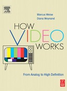
There is another color bar display that is helpful in setting up a color monitor. These bars are referred to as PLUGE bars, stands for Picture Line Up Generating Equipment. PLUGE bars contain the standard color bar pattern, plus two additional references. The first reference is a set of three color chips and one white chip separated by three black chips going across the lower third of the screen (Figure 7.2). The second reference is two additional black chips within the larger black chip in the lower right-hand corner of the screen.
The four chips that appear across the lower third of the screen are used for setting the hue and saturation of the monitor. The four chips—blue, magenta, cyan, and white—each separated by black, are in the reverse order from the color bars. All four chips contain the color blue. With the red and green displays turned off, there is a blue chip under each of the blue bars. Without PLUGE bars, it was necessary to scan the entire monitor and try to balance the four color bars against each other across the screen. With the use of the PLUGE bar signal, the eye does not have to cover such a wide area when comparing signals.
Figure 7.2 PLUGE Bar Signal
Use the hue and saturation controls as above to make all the blue bars, and the chips underneath them, the same. The additional black chips in the black field aid in setting brightness. One chip is 3.5 units of video, or blacker than analog black. The other is 11.5 units, or dark grey. These are in addition to the 7.5 units of analog black.
The proper brightness for the monitor can be set by adjusting the brightness control until the 11.5-unit chip is just barely visible. If the brightness is set too high, the 3.5-unit chip becomes visible. If the brightness is set lower than the point at which the 11.5-unit chip is just visible, the colors will appear dull and the picture dark.
If everything was adjusted correctly, the white chip in the color bar image will appear pure white without a hue and the black will appear pure black with no color shading. Once a good monochrome image has been set, the next step is to restore color to the monitor. Whatever procedure was used to turn color off should now be reversed to turn color back on. Color bars continue to be used as the video input signal and color reference.
Some monitors have a switch marked Set Up. This switch collapses the vertical drive so that the picture is reduced to a line or bar across the tube. This acts as an aid in setting up the basic balance of the three colors. However, the reduced scan may have a different color balance than the full picture, and therefore may not be totally reliable.
Once the monitor is set up correctly, the details of the electronic video signal can be viewed on scopes.