Analog Vectorscopes
The vectorscope is another type of oscilloscope used in measuring the video signal. Unlike the waveform monitor, which measures the luminance aspects of a video signal, a vectorscope is used to measure the hue.
The vectorscope, like the waveform monitor, is made up of a CRT, graticule, and knobs and buttons. The lines and markings on the graticule are used as the framework under which the chrominance of the signal is displayed for reference. The controls adjust the placement of the chrominance display pattern. Other vectorscopes may have controls in a different configuration, but the functions detailed in this chapter will be available on all models. To clearly introduce the concepts of a vectorscope, the Tektronix 1720, with dedicated controls, will be used as a reference.
Graticule
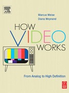
As with waveform monitors, vectorscopes have a small CRT that displays the signal. The CRT lies behind a glass or plastic plate inscribed with a circle that has markings and lines, which is the graticule (Figure 9.1). The markings on the circle itself represent degrees from 0 to 360. The thinner, individual notches or markings represent differences of 2°. The bolder markings represent 10° intervals. The 0° point or mark is at a nine o’clock position on the scope. The degree markings move in a clockwise position from that point.
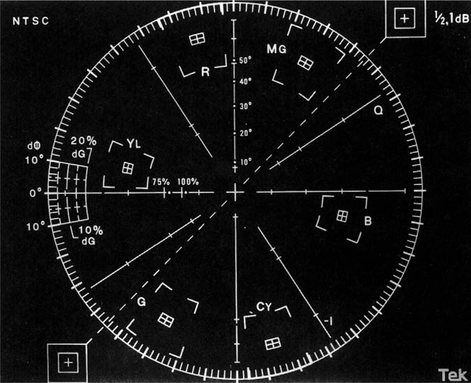
Figure 9.1 Vectorscope Graticule
Axes
There are two perpendicular lines that cut horizontally and vertically through the circle. The line that goes from 0° to 180° is referred to as the X axis. The up and down line that goes from 90° to 270° is called the Y axis. The Q axis is in the upper right-hand quadrant, and the -I axis is in the lower right quadrant of the circle.
Vector Readings
On the graticule, there are individual boxes that are located within the circle. Starting from the nine o’clock position and moving clockwise, these are yellow (YL), red (R), magenta (MG), blue (B), cyan (CY), and green (G). The three primary colors, red, blue, and green, are each separated by one of the secondary colors. The secondary color is a mixture of the two primary colors on either side of it. The box placement represents the direction or hue of a particular vector. The boxes are also used as an indication of the correct length of a vector, or its saturation.
The small boxes that are indicated for each color are correct SMPTE/NTSC specifications for the phase and amplitude of that particular color in the color bar test signal. The larger box that surrounds each small box is the allowable range that a color can vary in transmission and still be considered correct. If a color does not meet the exact specification, but is within tolerance, it is considered acceptable for test purposes.
The proper setup of the chrominance signal for color bars should show the center point of the signal aligned with the center point of the circle scale. The burst of the color subcarrier signal, the short line on the X axis, should point directly to the nine o’clock position. Much like a video image on the waveform, the color bars are designed to fit into specific color boxes in the vectorscope. Viewing the video image of a signal other than color bars will not appear as exact or ordered as the color bar test signal appears.
Setup Controls
Using as a reference the Tektronix 1730, the controls for general setup and adjustment of the vectorscope are on the right-hand side (Figure 9.2), and are divided into six sections. Section 4 has three knobs. The knob farthest to the left is FOCUS, for making the signal as sharp and clear as possible. The knob to the right of the focus is SCALE which controls scale illumination or the brightness of the graticule. The knob to the right of that is INTENS which controls the intensity of the waveform picture on the CRT.
Directly above the INTENS knob is the PHASE control, which rotates the whole display clockwise or counter-clockwise. Directly beneath the intensity knob is the POWER switch, which turns the vectorscope on and off.
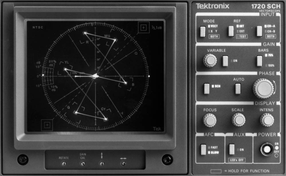
Figure 9.2 Vectorscope
Section 2 has two controls. The BARS button on the right adjusts the size of the vector display depending on the type of color bar display being viewed. The standard SMPTE color bars in their various configurations (full field, EIA split field, PLUGE, etc.) are a 75% test signal. If the test bars being used are a 100% signal, which is an option on a color bar generator, they will not fit the vectorscope unless this button is used.
To the left of the BARS button is the VARIABLE control. If the VARIABLE button is pressed, the knob can be used to vary the size of the display. This is useful when trying to time in or synchronize a piece of equipment. By enlarging the display, any variation in phase between two sources will be easier to see. The VARIABLE button is usually left OFF unless this adjustment needs to be made.
Input Selections
Section 1 has three buttons. The one on the left marked MODE will select a standard vector display. If MODE is pressed, it will switch the display to an X/Y or R-Y/B-Y mode. In this mode, all the vectors are compressed into those two vectors. Holding in the MODE button will show both displays simultaneously.
The center button marked REF, for reference, is used to select the synchronizing source for the vectorscope. When INT or internal is selected, the scope will supply its own synchronizing signal. If switched to EXT or external, it will use the external source feeding it for its synchronization. When timing in pieces of equipment, the switch should be set on EXT so that any differences between the various pieces of equipment will be seen.
If the REF button is held in, two test circles will be displayed. One test circle will appear at the outer edge of the graticule circle and the other is formed by the rotation of the burst. This display, when used in conjunction with the GAIN CAL or calibration gain control under the CRT, is used to calibrate or adjust the vectorscope. It is the equivalent of the calibration pulse on the waveform monitor.
The button on the far right of section 1 selects one of two inputs that are available to the scope. The two inputs are referred to as CH-A and CH-B or Channel A and Channel B. Having two inputs is helpful in situations where one scope is shared by two machines. Holding in the BOTH button will display both inputs simultaneously.
In section 3, to the left of the PHASE control knob, is a button marked SC/H, which stands for Subcarrier/Horizontal phasing. The principles of subcarrier/horizontal phasing are discussed in Chapter 20, Operations Overview. Pressing the SC/H button will show a small dot on the vectorscope at the left edge of the circle opposite the burst. The position of this dot will indicate if the signal feeding the scope is properly SC/H phased, and if it is not, how far out of phase it is.
In section 5, a button marked AUXILIARY can display the matching vector readout of the selections made on the Tektronix 1730 waveform monitor if both scopes are connected and used together.
Calibration
Under the CRT in section 6 are four adjustments for the display itself. The control on the far left, ROTATE, will rotate the display very much like the phase knob. However, this adjustment is meant for setting up the scope, rather than rotating, for purposes of comparison between signals.
The next control to the right is GAIN CAL for calibrating the size of the display. It can be used in conjunction with the REF button in section 1. In this manner, the display can be adjusted so that it can be used to accurately measure vectors.
The two controls on the right of section 6 will move the display up or down and left or right. Using the point where the vectors come together as the center of the display, these controls allow the movement of the display to be in the center of the graticule.
During active video, the vectors will not be quite so straight because they represent the variety of colors in the television picture rather than the pure colors that exist in a color bar signal.
PAL Signal
The PAL color difference signals are encoded on two separate subcarriers. On a vectorscope, the signal appears with two sets of color information, appearing like a double NTSC signal (Figure 9.3).
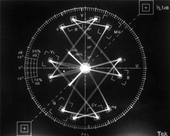
Figure 9.3 PAL Vector Display
To minimize cost and equipment space, current scopes combine waveform and vectorscopes and even audio signals into one scope. Rather than having dedicated buttons and knobs, these scopes have soft keys that are menu driven (Figure 9.4).
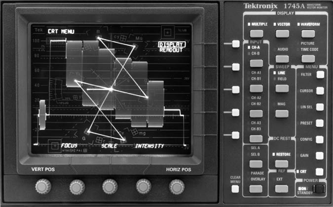
Figure 9.4 Dual Scope
Scopes will continue to vary in design from manufacturer to manufacturer and will continue to add additional features. However, all will use the current standards and measuring guides.