


DS8880 Storage Management GUI
This chapter describes the DS8000 Storage Management GUI that is available with the DS8880 (R8.1). It allows you to perform these functions on the storage system:
•Initial system setup for a new installation
•Activation of licensed functions
•Simplified logical configuration for open systems and IBM z Systems
•Advanced logical configuration for open systems and IBM z Systems
•Graphical view of system resource availability
•System status and events viewer
•Access to advanced help and the IBM Knowledge Center
•Performance monitoring and statistic offload
This chapter covers the following topics:
•Monitoring system events
•Audit logs and syslog notifications
11.1 Introduction
The Storage Management GUI (DS8000 GUI) includes a performance monitoring feature as an additional function of the enhanced GUI that was introduced with DS8870 Release 7.5.
The DS8000 GUI was designed and developed with three major objectives:
•Speed: A responsive GUI is a requirement.
•Simplicity: A simplified and intuitive design can drastically reduce the total cost of ownership (TCO).
•Commonality: Common graphics, widgets, terminology, and metaphors facilitate the management of multiple IBM storage products and software products.
With these deliverables in mind, a system administrator can use the DS8000 GUI to configure the storage system logically and prepare the storage system for I/O within an hour of completing the system setup. Then the system administrator can manage the system with minimal knowledge. The GUI provides a performance monitoring tool for the main storage parameters.
Logical storage configuration is streamlined in the DS8000 GUI. Creating and configuring pools is simpler. The architecture was changed to combine array site, array, and rank into a single resource, which is referred to as an array. The storage system can automatically manage device adapter (DA) pairs and balance arrays and spares over the two processor nodes.
The process for creating volumes is simplified. The system can automatically balance volume capacity over a pool pair. If storage needs require that the user balances arrays, spares, and volume capacity manually, the DS8000 GUI also provides custom options for configuring pools and volumes.
Configuring connections to hosts is easier and consistent with other IBM storage products. Hosts and host ports replace host connections and volume groups. From the data storage command-line interface (DS CLI) and DS8880 perspectives, these objects still exist, but they are created in the background.
The underlying architecture and virtualization are not changed, but the GUII navigation and its wizards make those more intuitive and self-explanatory. For more information about DS8880 virtualization, see Chapter 4, “Virtualization concepts” on page 93.
The storage system status can be viewed at any time in the pods that are displayed on the bottom of each page. The status and attributes of all hardware elements are displayed on the system page. All changes to the storage system, whether they were initiated by a user or the system, can be viewed on the Events page. Alerts are displayed at the bottom of each page and they link to the Events page.
Additionally, functions that include user access, licensed function activation, and modifying power or I/O port protocols, are available to the system administrator.
The DS8000 GUI provides performance metrics that are grouped into four sections:
•Storage System (all DS8880 performance metrics)
•Array (array level performance metrics)
•Pool (pool-dependent performance metrics)
•I/O Port (I/O port-dependent performance metrics)
The DS8000 GUI provides links to the Storage Management IBM Knowledge Center, User Learning tutorials, and context help.
Known limitations exist for the current release of the DS8000 Storage Management GUI. Directions are provided to access the previous DS GUI for advanced functions that are not available with the new GUI. For more information, see 11.10, “Accessing the previous DS GUI” on page 326.
If required, the DS command-line interface (DS CLI) can be used to manage functions that are not supported in this release of the DS8000 Storage Management GUI.
11.2 DS8000 Storage Management GUI: Getting started
This section describes how to accomplish the following tasks:
•Accessing the DS8000 Storage Management GUI
•Using the Storage Management Setup Wizard
•Managing and monitoring the system
•Performance monitoring the system
•Using the Help functions
11.2.1 Accessing the DS8000 Storage Management GUI
The Storage Management GUI can be accessed in the following ways:
•With a browser that is connected to the DS8880 Hardware Management Console (HMC)
•By using IBM Spectrum Control that has connectivity to the HMC
Accessing the Storage Management GUI with a browser
Web browsers including Mozilla Firefox, Microsoft Internet Explorer, and Google Chrome are supported for the DS8000 GUI.
The DS8880 supports the ability to use a single point of authentication function for the Storage Management GUI through a centralized Lightweight Directory Access Protocol (LDAP) server. This capability is supported locally by the internal Copy Services Manager (CSM) or through external proxy by IBM Spectrum Control. For more information about remote authentication and LDAP for the DS8880, see IBM DS8880 Integrated Copy Services Manager and LDAP Client on the HMC, REDP-5356.
The DS8000 GUI has a new URL. The DS8000 GUI can be accessed from a browser by using the http address that is shown in Example 11-1. In this address, HMC_IP is the IP address or host name of the Management Console (MC). You are not required to specify a port ID as in previous releases of the DS8000 GUI.
Example 11-1 DS8880 Storage Management GUI URL
https://<HMC_IP>
On a new storage system, the user must log on as the administrator. The password will expire and the user is forced to change the password. Figure 11-1 shows the following information:
1. Storage Management GUI URL: https://<HMC_IP>
This Storage Management GUI URL is configured by the IBM service support representative (IBM SSR) during the installation.
2. Initial login on the new machine
For a new machine, the following logon credentials are required:
– User = admin
– Password = admin
3. The default password is expired, and the user is forced to change the password for the admin user ID.
4. Service Management icon (the ‘Wrench’)
Clicking the Service Management icon opens a new window to the Management Console Web User Interface (WUI), which can be accessed to perform the following tasks:
– View open problems
– Manage remote access
– Restart the enterprise storage server network interface (ESSNI)
– Perform various other tasks

Figure 11-1 Storage Management GUI initial login
11.2.2 Storage Management GUI System Setup wizard
For a new storage system installation, the DS8000 GUI starts the System Setup wizard. The setup wizard starts automatically after the admin password is changed and a user with the Administrator role and authority logs in.
The setup wizard guides the admin user through the following tasks:
1. Set the system name.
2. Activate the licensed functions.
3. Optional: Start a logical configuration.
4. Provide a summary of actions.
The System Setup window opens the Welcome window, as shown in Figure 11-2.

Figure 11-2 System Setup - Welcome window
Starting with the Welcome window, complete the following steps:
1. Click Next. The System Name window opens. The default entry is the storage system serial number, which is shown in Figure 11-3. The user can create a preferred system name that complies with the name convention that is used in their environment.

Figure 11-3 System Setup - System Name window
2. Click Next. The Licensed Functions window opens. Click Activate Licensed Functions as indicated in Figure 11-4.

Figure 11-4 System Setup - Licensed Functions window
3. The Activate Licensed Functions window opens. Keys for licensed functions that have been purchased for this storage system need to be retrieved using the Machine Type, Serial Number, and Machine Signature. The keys can be stored in a flat file or an XML file. Licensed function keys are downloaded from the Data storage feature activation (DFSA) website:
Figure 11-5 shows the Activate License Functions window, the help information, and the activation of the licensed functions. For more information about licensed functions, see Chapter 9, “IBM DS8880 features and licensed functions” on page 217.

Figure 11-5 System Setup - Activate Licensed Functions
4. When the licensed functions are activated, the Configuration window opens, as shown in Figure 11-6. Select the storage type, either Fixed block (FB) for open systems, Count key data (CKD) for z Systems, or both.

Figure 11-6 System Setup - Configuration - Storage Type
5. Click Next to open the Pool Configuration window, which is shown in Figure 11-7. You can use this window to configure a single pool pair.
|
Note: If the IBM Easy Tier license is activated, that pool pair is managed by Easy Tier, by default. For more information about Easy Tier, see IBM DS8000 EasyTier, REDP-4667.
|
Optional: You can choose to configure all pools later. Configuring pools is covered in 11.4, “Logical configuration overview” on page 264.

Figure 11-7 System Setup - Configuration - Pool Configuration
6. Click Next to open the Summary window, which is shown in Figure 11-8. If everything looks correct, click Finish to exit the System Setup Wizard.
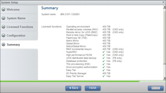
Figure 11-8 System Setup - Summary
The wizard closes and the System window opens.
11.2.3 Managing and monitoring the storage system
When the initial system setup is completed, the system page is displayed. This page is the first page that opens after a user logs in. The system page displays the major hardware components of the DS8880 storage system and shows the status of the system hardware. You can return to this page at any time by clicking the Home/Name icon in the upper left of the GUI.
Figure 11-9 on page 255 shows the System window, with no selected or highlighted object.
From the System window, the user can manage the system by accessing actions:
•Controlling how the system is powered on or off
•Modifying the I/O port protocols
•Modifying Easy Tier settings
•Viewing system properties
•Displaying performance monitoring graphs
The system administrator can create and modify the logical configuration of the system. Details can be viewed about each hardware component by right-clicking (or pointing to) the component to display an enlarged view and the current state of that component.

Figure 11-9 The DS8880 System window
Figure 11-10 presents a high-level overview of the System window and all the objects that can be accessed from this window. Not all functions display for every user role. For more information about user roles, click Help and search for user role.

Figure 11-10 System window comprehensive view
The numbered labels in Figure 11-10 on page 255 have these meanings:
1. Home/Name icon:
– The name of the DS8000 storage system as set by the administrator.
– Click the Name/Home icon from anywhere to return to the System window.
2. Actions menu:
– Rename
Change the name of the DS8880 storage system.
– Modify I/O Port Protocols
Select the protocol that is used by I/O ports to connect the storage system to a host or to another storage system. The user can also display the properties of the selected port. Port error rates are not available from this view, and must be accessed by clicking Settings → Network Fibre → Channel Ports.
– Power Off/On
Initiate power off or power on of the DS8880 storage system, as required.
– Properties
View the properties of the DS8880 storage system:
• Current state of the DS8000 storage system
• Release and bundle version of the IBM system software
• Machine type and model
• Unique serial number
• Signature (string of characters that identifies a DS8000 storage system), which is used to retrieve license keys from the IBM DSFA website
• Worldwide Node Name of the system
• Hardware component summary (such as processor type, total subsystem memory, raw data storage capacity, or number of I/O ports)
• Last power on time stamp
3. Frame:
Use the frame selector view (on the right of the system page) to select an individual frame view of a multi-frame storage system for display, if applicable. The frame selector is not displayed if the storage system has only one frame.
4. User icon:
– Log out of the DS8000 GUI, and display the login page.
– Modify Password: The logged in user can change their own password.
5. Help icon:
This icon opens a drop-down menu that includes the following options:
– The first line in this menu is context-sensitive help. The context-sensitive help pages describe the resources and actions that are available in the GUI, and they open a separate window for the DS8000 GUI IBM Knowledge Center.
– What’s New: This option provides descriptions on new features contained in this release of the GUI with a link to the DS8000 GUI IBM Knowledge Center for usage of each of the new functions. Also provided is a link to discover functions that are supported in this release, and where to find those that are not.
– Learning and Tutorials: This option opens a separate window for the DS8000 GUI IBM Knowledge Center, at the Overview → Learning and Tutorials section. This section contains e-learning modules that introduce the DS8880 storage system family, define key concepts, and provide an overview of related installation, configuration, and administration tasks.
– Help Contents: This option opens a separate window for the DS8000 GUI IBM Knowledge Center main page.
– Previous GUI: This option opens a separate window to the login window of the previous generation’s DS GUI. The latest release of the DS8000 Storage Management GUI does not support all of the functions of the previous GUI. The list of limitations is in the DS8000 GUI IBM Knowledge Center. (Click Help → Troubleshooting → Limitations.)
– About DS8000: This option opens the DS8000 Storage Management window, which shows the following information:
• Current release 8.x of Licensed Internal Code (LIC) bundle 88.x.x.x
• Product, for example, DS8888
• Machine type and model (MTM) 283x-98x
• Machine Serial Number (S/N) 75xxxxx
For more information about DS8880 help functions, see 11.2.4, “Storage Management help functions” on page 260.
6. Monitoring menu:
– System: This option opens the System window.
– Events: This option opens the Events window.
– Performance: This option opens the new Performance (statistics) window.
7. Pools menu:
Two options are available here:
– Arrays by Pool: Access this menu to view the pool configuration. This menu can be used only by users with the monitor or copy operator role.
– Volumes by Pool: Access this menu to create, modify, or delete pool pairs. This menu can be used only by users with the administrator or logical or physical operator role.
8. Volumes menu:
– Access this menu to view the volume configuration. This menu can be used only by users with the monitor or copy operator role.
– Access this menu to create, modify, or delete volumes by users with the administrator or logical or physical operator role.
9. Hosts menu:
– Access this menu to view the hosts’ configurations. This menu can be used only by users with the monitor or copy operator role.
– Access this menu to create, modify, or delete hosts. This menu can be used only by users with the administrator or logical or physical operator role.
10. User Access menu:
– Only users with the administrator role can access this menu.
– This menu opens the Users window.
– A system administrator can use this menu to perform the following actions:
• Create user accounts.
• Set a user account role.
• Set temporary passwords (to be reset at first use by the new account).
• Modify an existing user account role.
• Reset an existing user account password.
• Disconnect a user account.
• Determine a user account connection (DS CLI or GUI).
11. Settings menu:
– Network:
• Modify Fibre Channel ports protocol for a selected port or group of ports.
• Display error rates for a selected port or group of ports.
• Display a single port’s properties.
– Security:
• Manage encryption for the storage system.
• Manage local password rules (such as password minimum length, expiration, and age).
• Perform HMC access management.
– System:
• Licensed Function
This window displays a summary of the activated licensed functions. When you click the Activate tab, the Activate Licensed Functions window opens, where you can activate additional licenses. For a full description of activating licensed functions, see Chapter 9, “IBM DS8880 features and licensed functions” on page 217.
• Easy Tier
You can use this function to configure Easy Tier to improve performance by managing or monitoring volume capacity placement in pools. Easy Tier Heat Map Transfer utilities can also be enabled.
• Advanced configuration
On the Advanced tab of the System settings page, you can configure I/O Priority Manager, enable ESSNet Copy Services, set the IBM i serial number prefix, select the power control mode for the storage system, and enable the DS Open API (CIM Agent).
– Notifications:
• Syslog
You can define, modify, or remove Syslog servers.
– Support:
• Access
You can enable or disable IBM service access to the Hardware Management Console (HMC) by using SSH or the DS Service GUI. An Assist On-site (AOS) connection to the HMC for IBM service is also enabled from the Access tab.
– GUI Preferences:
• Navigation
You can enable or disable animation of the navigation dock in the GUI.
• Login Message
You can enter a message that is displayed when users log in to either the DS GUI or DS CLI.
• General
You can refresh the browser cache for the GUI and set the default logout timeout.
12. Export storage system summary
As administrator, click the Diskette icon to save a DS8880 configuration to a comma-separated values (CSV) file.
13. Component View:
– The large graphic of one of the frames in the DS8880 system is shown.
– Use your mouse pointer to ‘hover-over’ an enclosure, node, HMC, or uninterruptable power supply (UPS), and a Properties menu opens that shows basic information about that particular component in the frame.
– If a Magnifying Glass icon appears when hovering over a component, left-click to bring the component to the center of the window and allow properties for sub-components to be displayed. Click anywhere on the window to return the component to the DS8880 system.
– When viewing an I/O port on a Host Adapter, you can right-click a port to modify the I/O port protocol.
The following information is typically displayed for an enclosure:
• Enclosure name
• ID
• State, for example, online, offline, or service required
• Enclosure-specific data
• Enclosure serial number
The following information is typically displayed for a node:
• ID
• State, for example, online, offline, and service required
• DS8880 release
• Data that is specific to a Power System
– For more information about the Component view, see 11.7, “Monitoring system health” on page 305.
14. Frame Selection:
An icon exists for each frame in the system. By selecting a frame icon, that frame is then visible as the enlarged view immediately to the left, where the frame’s components can be viewed.
15. Status Area:
The status area consists of the following objects:
– Capacity: Changes that affect the capacity of the storage system are displayed in the Capacity pod on the left side of the status area at the bottom of the Storage Management GUI. Click the Capacity pod to go to the Arrays by Pool window.
– Performance: I/O throughput is displayed in the Performance pod in the middle of the status area at the bottom of the Storage Management GUI. Click the Performance pod to go to the Performance page.
– System health: Changes that affect data accessibility and hardware states are displayed in the System health pod on the right side of the status area at the bottom of the Storage Management GUI. If a hardware error is displayed, click the System health pod to go to the System window, where you can observe the hardware component that needs attention. For more information about system events, see 11.7, “Monitoring system health” on page 305.
– Alerts: If any changes are generated by DS8880, an additional icon that is called Alerts is displayed, which shows the number of recent alerts. Click the Alerts icon to go to the Events window.
11.2.4 Storage Management help functions
The DS8880 Storage Management GUI provides access to comprehensive help functions. The help functions not only assist you with using the GUI, but also provide in-depth help to the overall DS8880 Storage System and functions. To access the help contents, click the Help icon, then select Help Contents to open a separate window for the DS8000 GUI IBM Knowledge Center main page, as illustrated in Figure 11-11.

Figure 11-11 Storage Management Help System - IBM Knowledge Center
From the IBM Knowledge Center, you can discover introductory information about the DS8880 architecture, features, and advanced functions. Also, you can learn about management interfaces and tools. Many tutorials and videos can help you understand the product.
You can obtain more information about using the Storage Management GUI for common tasks, such as these:
•Logically configuring the storage system for open systems and z Systems attachment
•Configuring open systems host attachment
•Managing user access
The IBM Knowledge Center also provides links to external links for more information about IBM storage systems, and other related online documentation.
11.3 System configuration overview
After the DS8880 administrator configures the initial system, the administrator can configure additional system functions according to the storage requirements.
11.3.1 Security settings
Security is always important. Specifically, if you want to use the data-at-rest encryption capability with the DS8880, you must set it before you store any data on the system.
Encryption
To enable encryption, from the system page, click the Settings icon. Click Security to open the Security window, and click the Encryption tab.
|
Important: If you must activate encryption for the storage system, ensure that the encryption license is activated and the encryption group is configured before you begin any logical configuration on the system. When pools exist, you cannot disable or enable encryption. For more information, see IBM DS8880 Data-at-rest Encryption, REDP-4500.
|
Figure 11-12 shows the Encryption configuration window.

Figure 11-12 Encryption settings for DS8880 Release 8.0
Local password rules
Many companies have their own security policies for passwords, and want to implement the same policies for their DS8880 storage system.
To implement password rules, from the system page, click the Settings icon. Click Security to open the Security window, and click the Local Password Rules tab. Figure 11-13 shows the password configuration window.

Figure 11-13 Local password settings
11.3.2 Easy Tier settings
|
No charge: Easy Tier is a no-charge feature of the IBM DS8000. However, as with any other acquired licensed function, the Easy Tier licensed functions must first be ordered from IBM.
|
From the DS8000 GUI, you can manage Easy Tier on the system level. From the System window, select the Settings icon. Click System to open the System window, and click the Easy Tier tab to open the Easy Tier settings window, as shown in Figure 11-14.

Figure 11-14 System-level Easy Tier settings
For more information about Easy Tier, see IBM DS8000 EasyTier, REDP-4667.
11.3.3 Advanced settings
The Advanced settings window is shown in Figure 11-5.

Figure 11-15 DS8880 Advanced settings
By using the Advanced settings window, you can, for example, set up the I/O Priority Manager mode and the power control mode.
I/O Priority Manager
You can use the I/O Priority Manager to manage quality of service (QoS) levels for each application that is running on the system.
|
Note: The I/O Priority Manager licensed function must be activated on your DS8000 storage system. The default setting for this feature is disabled, so it must be enabled for use.
|
The I/O Priority Manager aligns distinct service levels to separate workloads in the system to help maintain the efficient performance of each volume. The I/O Priority Manager detects when a higher-priority application is hindered by a lower-priority application that is competing for the same system resources. This detection might occur when multiple applications request data from the same drives. When the I/O Priority Manager encounters this situation, it delays lower-priority I/O data to assist more critical I/O data to meet its performance targets.
From the System window, click the Settings icon. Click System to open the System window. Click the Advanced tab to open the window to use to manage I/O Priority Manager mode, as shown in Figure 11-15 on page 263. You can choose I/O Priority Manager to manage or monitor capacity. You can also choose to receive Simple Network Management Protocol (SNMP) notifications about I/O Priority Manager activity.
Power control mode
You can determine how to control the power supply to the storage system. From the System window, click the Settings icon. Click System to open the System window. Click the Advanced tab to open the window to manage Power control mode (as shown in Figure 11-15 on page 263). The following options are available:
•Automatic: Control the power supply to the storage system through the external wall switch.
•Manual: Control the power supply to the storage system by using the Power Off action on the System window.
11.4 Logical configuration overview
Before you configure the storage system, it is important to understand the storage concepts and the sequence of the system logical configuration.
Figure 11-16 illustrates the concepts of logical configuration.

Figure 11-16 Logical configuration sequence
The following concepts apply when you use the GUI to configure the storage:
•Array: An array, which is also referred to as a managed array, is a group of storage devices that provides capacity for a pool. An array generally consists of seven or eight drives that are managed as a Redundant Array of Independent Disks (RAID).
•Pool: A storage pool is a collection of storage that identifies a set of storage resources. Pools provide the capacity and management requirements for arrays and volumes that have the same storage type, either FB for open systems or CKD for z Systems.
•Volume: A volume is a fixed amount of storage on a storage device.
•LSS: The logical subsystem (LSS) enables one or more host I/O interfaces to access a set of devices. An LSS also is known as a logical control unit (LCU) in z Systems.
•Host: The computer system that interacts with the DS8880 storage system. Hosts that are defined on the storage system are configured with a user-designated host type that enables DS8880 to recognize and interact with the host. Only hosts that are mapped to volumes can access those volumes.
The logical configuration of the DS8880 storage system begins with managed arrays.
When the storage pools are created, the arrays are assigned to the pools and then volumes are created in the pools. FB volumes are connected through host ports to an open system host. CKD volumes require that logical subsystems (LSSs) are created as well so that they can be accessed by an IBM z Systems host.
Pools must be created in pairs to balance the storage workload. Each pool in the pool pair is controlled by a processor node (either CPC 0 or CPC 1). Balancing the workload helps to prevent one node from performing most of the work and results in more efficient I/O processing, which can improve overall system performance. Both pools in the pair must be formatted for the same storage type, either FB or CKD storage. Multiple pools can be created to isolate workloads.
When you create a pool pair, all available arrays can be assigned to the pools, or the choice can be made to manually assign them later. If the arrays are assigned automatically, the system balances them across both pools so that the workload is distributed evenly across both nodes. Automatic assignment also ensures that spares and DA pairs are distributed equally between the pools.
If the storage will connect to a z Systems host, you must create the LSSs before you create the CKD volumes.
It is possible to create a set of volumes that share characteristics, such as capacity and storage type, in a pool pair. The system automatically balances the capacity in the volume sets across both pools. If the pools are managed by Easy Tier, the capacity in the volumes is automatically distributed among the arrays. If the pools are not managed by Easy Tier, it is possible to choose to use the rotate capacity allocation method, which stripes capacity across the arrays.
When you plan your configuration with the DS8880, all volumes, including standard provisioned volumes, consume metadata capacity when they are created, which allows the size of the reserved area to be reduced. The 1 GB extents that are allocated for metadata are subdivided into 16 MB subextents. The metadata capacity of each volume that is created affects the configuration planning. Figure 11-17 shows an example of the required metadata capacity when you create volumes.

Figure 11-17 Metadata capacity that is consumed on volumes
If the volumes will connect to a z Systems host, the next steps of the configuration process are completed on the host. For more information about logically configuring storage for z Systems, see 11.6, “Logical configuration for count key data volumes” on page 289.
If the volumes will connect to an open system host, map the volumes to the host, and then add host ports to the host and map them to I/O ports on the storage system.
FB volumes can accept I/O only from the host ports of hosts that are mapped to the volumes. Host ports are zoned to communicate only with certain I/O ports on the storage system. Zoning is configured either within the storage system by using I/O port masking, or on the storage area network (SAN). Zoning ensures that the workload is spread correctly over I/O ports and that certain workloads are isolated from one another.
|
Note: Starting with Release 8.1 of DS8880 microcode, a “Force deletion” option is available when deleting a volume in the GUI. This feature was previously only available when deleting a volume through the DS CLI.
|
11.5 Logical configuration for fixed-block volumes
This section describes the logical configuration for FB volumes for open systems hosts. It covers the following topics:
•Simple FB logical configuration flow
•FB pool creation
•Quick FB volume creation
•Advanced FB volume creation
•Creation and connection of FB volumes to open system hosts
11.5.1 Configuration flow
As with the earlier releases of DS8000 Storage Management GUI, the logical configuration for FB for open systems is greatly simplified, and can now be accomplished with a few steps. Figure 11-18 shows the logical configuration flow for FB.
The following steps are used for logical configuration for FB volumes:
1. Create a pool pair.
2. Create the FB volumes.
3. Attach to open system hosts.

Figure 11-18 Logical configuration flow for open systems
11.5.2 Creating FB pools
For best performance and a balanced workload, create two pools. The Storage Management GUI helps the system administrator to create a balanced configuration by creating pools as a pair. The pools are configured so that one pool of the pair is managed by node 0 and the other pool of the pair is managed by node 1.
|
Note: If the requirement is to create a single pool, see “Creating a single pool” on page 271.
|
To create an FB pool pair, complete these steps:
1. From the System window, click the Pools icon.

Figure 11-19 Create Pool Pair tab
|
Note: When you automatically assign arrays when you create a pool pair, the arrays are created as RAID 5 arrays by default. To configure RAID 6 or RAID 10 arrays, you must use the advanced configuration for pool creation, or assign the arrays manually to an existing storage pool from the unassigned arrays.
|
3. Click the Create Pool Pair tab. The Create Pool Pair window opens.
4. Specify the pool pair parameters, as shown in Figure 11-20:
– Storage type: Ensure that Fixed Block (FB) is selected.
– Name prefix: Add the pool pair name prefix. A suffix ID sequence number is added during the creation process.

Figure 11-20 Create FB pool pair and assign arrays to a pool pair
5. Select from the listed drive types and select the number of arrays for each drive type that you want to assign to the pool pair.
|
Important: The number of specified arrays must be even. Trying to specify an odd number results in a message that states “Arrays must be spread evenly across the pool pair”. The GUI increases the number of arrays by one to achieve an even number.
|
6. When pool pair parameters are correctly specified, click Create to proceed. Figure 11-21 shows a pool pair that is created and assigned arrays.

Figure 11-21 Pool pair that is created and assigned arrays
Creating FB Pools: Advanced Configuration
When creating FB storage pools, you can also specify the extent size and RAID level. With Release 8.1 of DS8880 microcode and later, you can specify large 1 GiB, or small 16 MiB extents for a storage pool or pool pair. The RAID level for the arrays can also be specified at creation time by using the advanced (Custom) configuration option.
To create a custom FB pool pair, complete these steps:
1. From the System window, click the Pools icon.
3. Click the Create Pool Pair tab. The Create Pool Pair window opens:
4. Specify the pool pair parameters, as shown in Figure 11-20 on page 268:
– Storage type: Ensure that Fixed Block (FB) is selected.
– Select the Custom option in the Advanced section.
– Name prefix: Add the pool pair name prefix. A suffix ID sequence number is added during the creation process.
– Extent size: Select 1 GiB for large extents, or 16 MiB for small extents.
5. Select from the listed drive types and select the number of arrays for each drive type that you want to assign to the pool pair.
6. Choose the RAID level for the selected arrays.
7. When pool pair parameters are correctly specified, click Create to proceed.
Figure 11-22 shows custom configuration options.
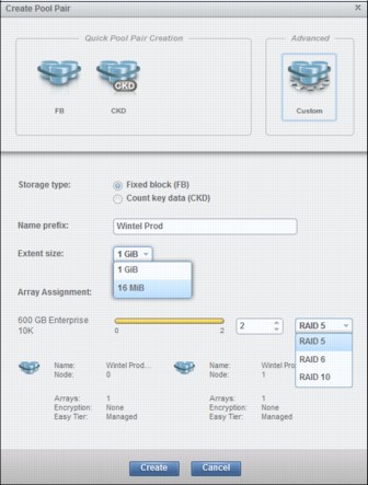
Figure 11-22 Configure FB Storage Pools with Advanced Options
Manually assigning arrays to existing pools
The storage administrator can manually unassign arrays or reassign assigned arrays to existing pools when the current configuration needs to be modified, such as when the administrator adds storage capacity. To manually assign arrays, complete these steps:
1. Select an array and click Assign or Reassign, as shown in Figure 11-23 on page 271. This action opens the Assign Array window.
2. Select the target pool from the drop-down list, and the RAID level that you want.
3. Select the Redistribute check box to redistribute all existing volumes across the pool, including the new array.
4. Click Assign.
|
Note: In a pool that is managed by Easy Tier, redistributing volumes across the pool is automatic. This redistribution is called Dynamic Pool Reconfiguration. See IBM DS8000 EasyTier, REDP-4667.
|

Figure 11-23 Manually assign an array to an existing pool
Creating a single pool
Occasionally, you are required to create a single pool, as opposed to creating a pool pair for balancing a workload. To create a single storage pool, complete these steps:
1. Create a pool pair, as shown in Figure 11-24. However, do not assign any arrays to new pool pair.
Figure 11-24 Create an empty pool pair with no assigned arrays
2. Click Create.
3. Choose one of the pools from the recently created pool pair to delete, as shown in Figure 11-25.

Figure 11-25 Delete one pool of the pool pair
4. Assign one or more arrays to the single pool, as shown in Figure 11-26.

Figure 11-26 Assign an array to a single pool
11.5.3 Creating FB volumes
Create a set of FB volumes by using the Create Volumes tab on either the Volumes window or the Volumes by Pool window. The maximum capacity for an FB volume is 16 TiB. The Storage Management GUI automatically distributes capacity across the two pools.
From the system page, select the Volumes icon. Four options are provided as shown in Figure 11-27:
•Volumes (All volumes are visible in single view.)
•Volumes by Pool (Volumes are grouped by pool.)
•Volumes by Host (Volumes are grouped by host.)
•Volumes by LSS (Volumes are grouped by LSS.)

Figure 11-27 Create FB volumes
Select any option to open the Create Volumes window (Figure 11-28).
The Storage Management GUI provides two options to create FB volumes:
•Quick Volume Creation
The intent of the Quick Volume Creation option is to simply create volumes with standard provisioning that are balanced across pool pairs.
•Advanced
This option is used for custom configuration when you either need to create thin-provisioned volumes, specify the extent allocation method (EAM), or select specific LSSs.
Create FB volumes: Quick volume creation
To used the Quick Volume Creation method, complete these steps:
1. On the Create Volumes window, click the FB icon, under Quick Volume Creation, as shown in Figure 11-28.

Figure 11-28 Create FB volumes by using the Quick Volume Creation option
2. The Create Volumes configuration window is displayed. By default, the Storage Management GUI tries to balance the volumes across the pool pair so that the workload is balanced across both nodes or central processor complex (CPC).
3. Enters the following user-specified values:
– Name prefix: User-defined name for volumes (A suffix ID sequence number will be added during the creation process.)
– Quantity: Number of volumes to be created in selected pools
– Capacity: The capacity of the volumes to be created. Volumes can be configured in the following increments:
• GiB or TiB
• Blocks
• IBM System i volumes
|
Note: IBM System i volumes are chosen from a list of fixed capacities. Currently, the GUI is limited because it cannot create variable-sized IBM i volumes.
|
In the example that is shown in Figure 11-29, 20 volumes of 400 GiB are created. Both pools of the pool pair are selected by default. The system allocates 10 volumes to each pool, balancing the workload.

Figure 11-29 FB volume creation window
Create FB volumes: Advanced configuration
To use the advance configuration option, complete these steps:
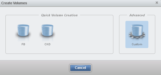
Figure 11-30 Create FB Volumes - Advanced
2. The Type window appears, as shown in Figure 11-31. By default, the Storage type that is selected is Fixed block (FB). For FB volume creation, two volume definition modes are available:
– Volume creation by volume sets
– Volume creation by LSS

Figure 11-31 Advanced - Define FB volumes by volume sets
3. Select the option that you want, then click Allocation Settings to open the Allocation Settings window that is shown in Figure 11-32.

Figure 11-32 Advanced - FB volume creation - Allocation method
4. Select the type of thin provisioning (Standard provisioning (none) or Extent space efficient (ESE) for FlashCopy.
5. If you select Standard provisioning or Extent space efficient, you can then select the extent allocation method (Rotate capacity or Rotate volumes).
6. You can enable the T10 - data integrity feature (DIF) only for FB volumes. Support for Linux on z Systems is available since Release 7.0 (for DS8870). T10-DIF is supported between AIX on POWER with 16 Gbps host bus adapters (HBAs) and the DS8880.
|
Note: When FlashCopy is used on FB volumes, the source and the target volumes must have the same protection type of either T10-DIF or standard.
|
7. If the volume definition mode was set to Define volume by volume sets, click the Volume Sets tab to display the Volume Sets window, as shown in Figure 11-33, and specify the following information:
– Pool selection: By default, a pool pair is selected to balance the workload across the nodes.
– Volume characteristics: The storage administrator defines the following user-determined values:
• Name prefix: User-defined name for volume set. (A suffix ID sequence number will be added during the creation process.)
• Quantity: Number of volumes to create.
• Capacity: The capacity of the volumes to create. Volumes can be configured in increments of GiB, TiB, blocks, or IBM System i volumes.

Figure 11-33 Advanced - FB volume creation - Volume sets
8. If the volume definition mode was set to Define volume by LSS, click the Volumes by LSS tab to display the Volumes by LSS window, as shown in Figure 11-34 on page 277, and specify the following information:
– Pool selection: By default, a pool pair is selected to balance the workload across the nodes.
– LSS range: The LSS IDs to create. If only a single LSS is required, make the range a single ID. For example, LSS range 30 - 30 creates a single LSS.
– Volume characteristics: The storage administrator defines the following user-determined values:
• Name prefix: User-defined name for volume in the LSSs. A suffix ID sequence number is added during the creation process.
• Quantity: Number of volumes to create for each LSS.
• Capacity: The capacity of the volumes to create. Volumes can be configured in increments of GiB, blocks, or IBM System i volumes.

Figure 11-34 Advanced - FB volume creation - Volumes by LSS

Figure 11-35 Advanced - FB volume by volume set - Summary
11.5.4 Creating FB host attachments
This section describes the steps that are required to attach FB volumes to open system hosts. You use this sequence:
1. Setting I/O port topology
2. Creating open systems clusters
3. Creating open systems hosts
4. Assigning host ports to hosts
5. Assigning FB volumes to open systems hosts
Setting I/O port topology
For an open system host to access FB volumes that are configured on the DS8880, the host must be connected to the DS8880 through a Fibre Channel connection (FICON). The Fibre Channel Protocol (FCP) must be configured on the I/O port so that the host can communicate.
DS8880 has two kinds of host adapters (HAs): 4-port 16 Gbps and 4-port or 8-port 8 Gbps Fibre Channel (FC) adapters. Each port can be independently configured to one of the following Fibre Channel topologies:
•Fibre Channel Arbitrated Loop (FC-AL): Only for 8 Gbps host adapters
•FCP: Also known as Fibre Channel-switched fabric (which is also called switched point-to-point) for open system host attachment, and for Metro Mirror, Global Copy, Global Mirror, and Metro/Global Mirror connectivity
•FICON: To connect to z Systems hosts, and for z/OS Global Mirror connectivity.
|
Note: FC-AL is not supported by 16 Gbps adapters.
|
For open system hosts, the I/O port must be configured as either FCP or FC-AL. To set the I/O port topology, complete these steps:
1. From the Storage Management GUI System window, click the Actions menu and select Modify I/O Port Protocols to open the Modify I/O Port Protocols window (Figure 11-36).

Figure 11-36 Modify I/O Port Protocols window
2. Select the port to modify. Multiple ports can be selected by using the Shift or Ctrl key.
3. From the Actions tab, click Modify Protocol to open the Modify Protocol window, as shown in Figure 11-37.

Figure 11-37 Modify I/O Port - Select a new protocol - single or multiple 16 and 8 Gbps ports
Figure 11-37 is divided into two main sections:
– Available protocols for 16 Gbps host adapters (for single or multiple ports that are selected)
– Available protocols for 8 Gbps host adapters (for single or multiple ports that are selected)
For open system host attachment, select either one of the following items:
– Small Computer System Interface (SCSI) FCP: For open system hosts that connect to a SAN.
– FC-AL: For open system hosts that are connected directly to the DS8880 (only for 8 Gbps).
4. Click Modify to perform the action.
Creating open system clusters and hosts
Starting with DS8880 Release 8.1 of the microcode, hosts of the same type can be grouped into a cluster for simplified volume mapping operations and management. Private volume mappings are supported, along with support of all cluster events and notifications. This section describes how to configure clusters and hosts by using the Storage Management GUI. For reference, a host port is the Fibre Channel port of the HBA Fibre Channel adapter that is installed on the host system. An I/O port is the Fibre Channel port of the HA that is installed in the DS8880.
To configure an open system cluster, complete the following steps:
1. Create a cluster: Configure a cluster object to access the storage system.
2. Create a host: Configure a host object to access the storage system.
3. Assign hosts: Assign hosts to a cluster object.
4. Assign a host port: Assign a host port to a host object by identifying one of the worldwide port names (WWPNs) of the HBA that is installed on the host system.
5. Modify the I/O port mask: Modify the I/O port mask to allow or disallow an I/O port that the host can use to communicate with the DS8880.
To configure an open system host, complete the following steps:
1. Create a host: Configure a host object to access the storage system.
2. Assign a host port: Assign a host port to a host object by identifying one of the WWPNs of the HBA that is installed on the host system.
3. Modify the I/O port mask: Modify the I/O port mask to allow or disallow an I/O port that the host can use to communicate with the DS8880.
Creating clusters
To configure a cluster object, complete these steps:
1. Click the Hosts icon in the Storage Management GUI System window

Figure 11-38 Configure hosts

Figure 11-39 Create Cluster
4. The Create Cluster window opens, as shown in Figure 11-40. Specify the name of the cluster, and click Create.

Figure 11-40 Create Cluster window
Creating hosts
To configure a host object, complete these steps:
1. Click the Hosts icon in the Storage Management GUI System window.
Figure 11-41 Configure hosts

Figure 11-42 Create Host
4. The Add Hosts window opens, as shown in Figure 11-43. Specify the following items:
– Name: The user-defined name for the host to add
– Type: This item represents the operating system of the host to add. Figure 11-43 shows the available host types.

Figure 11-43 Add Host window that shows all available host types
Assigning hosts to a cluster
If required, after a host is created, it can be assigned to a defined host cluster. To do so, complete these steps:
1. From the Hosts window, select the host to be assigned to a cluster.

Figure 11-44 Assign to Cluster
3. The Assign Host window opens as shown in Figure 11-45. From the drop-down list, select the cluster to add the host to.

Figure 11-45 Assign Host window
4. Click Assign to complete the action.
5. Repeat the previous actions to add all hosts that are required in the cluster. After you complete all the hosts, assigned hosts will be listed under the cluster in the Hosts window as shown in Figure 11-46.
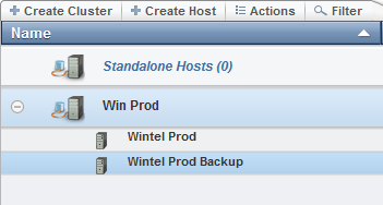
Figure 11-46 Hosts window showing the created cluster
Assigning host ports
After the host is added, host ports must be assigned to the defined host. To do so, complete these steps:
1. From the Hosts window, select the host to which to assign the host port. Either right-click, or from the Actions tab, select Assign Host Port, as shown in Figure 11-47.

Figure 11-47 Assign Host Port
2. This action opens the Assign Host Port to Host window. If the host that is being added is effectively connected to the DS8880, the available WWPNs are listed in the drop-down. If the host that is being added is not connected to the DS8880, the WWPN of the host HBA must be added manually.
Select from one of the WWPNs that are shown in the drop-down list in Figure 11-48, or manually enter the WWPN of the HBA of the host that you are adding. Click Assign.

Figure 11-48 Add a host port to an existing host
Typically, most open system hosts have multiple FC connections to the DS8880 for redundancy and performance. Ensure that all additional host WWPNs that are connected for this host are defined to the host object by using the same procedure.
Modifying the I/O port mask
When the host is configured, by default it has access to all I/O ports. To see this property, right-click a host object and select Properties, as shown in Figure 11-49.

Figure 11-49 Host properties with all I/O ports that are allowed for a host
If the system administrator wants to restrict the I/O ports that can communicate with the host, I/O port masking needs to be defined. Modify the I/O port mask to allow or disallow an I/O port that the host can use to communicate with the DS8880. To do so, complete these steps:
1. From the Hosts window, select the host to modify the I/O port mask. Right-click, or from the Actions tab, select Modify I/O Port Mask.
2. A list of the DS8880 I/O ports is displayed. Select one or more ports to disallow. You can use the Ctrl or Shift key for multiple selections.) Click Save. See Figure 11-50.

Figure 11-50 Modify I/O Port Mask - Disallow ports
The properties of the selected host now reflect the number of I/O ports that have access, as shown in Figure 11-51.

Figure 11-51 Host properties with I/O port masking
I/O ports can be selectively modified from disallowed to allowed by using the previous procedure.
11.5.5 Assigning FB volumes
FB volumes can accept I/O only from the host ports of hosts that are mapped to FB volumes. To map a volume to a host or a cluster, complete these steps:
1. From the Storage Management GUI system page, select Volumes by Host from either the Volumes icon or the Hosts icon, as shown in Figure 11-52.

Figure 11-52 Volumes by Host from the Volumes menu or the Hosts menu
2. The Volumes by Hosts menu opens. Select the volumes to map from the Unmapped Volumes list, as shown in Figure 11-53. From the Actions tab, or by right-clicking, select Map to Host or Cluster.

Figure 11-53 Map unmapped volumes to a host or cluster
3. The Map Volume to Host or Cluster window opens. Select the host or cluster from the list of configured stand-alone hosts and clusters, then click Map, as shown in Figure 11-54.

Figure 11-54 Map volumes to the selected host or cluster
|
Note: When mapping volumes to a cluster, volumes mapped to the cluster are public volumes that are seen by all hosts in the cluster. Volumes mapped to a single host in a cluster are private volumes.
It is the responsibility of the system administrator to ensure that the correct clustering software is implemented to ensure data integrity when a volume is mapped to more than one host.
|
Figure 11-55 shows a mix of public and private volumes mapped to a cluster.

Figure 11-55 Mapping volumes to a cluster.
11.6 Logical configuration for count key data volumes
This section describes the logical configuration for CKD volumes for z Systems.
11.6.1 Configuration flow
As with the historical Storage Management GUI, the logical configuration for CKD volumes is greatly simplified and can now be accomplished with a few steps and within a minimum amount of time.
Figure 11-56 shows the logical configuration flow for CKD.

Figure 11-56 Logical configuration flow for z Systems
Use these steps to logically configure CKD:
1. Create a CKD pool pair.
2. Create the CKD LSSs.
3. Create the CKD volumes.
4. Configure the parallel access volumes (PAVs).
5. Configure the I/O ports for FICON.
11.6.2 Creating CKD storage pools
For the best performance and a balanced workload, two pools must be created. The Storage Management GUI helps the system administrator to create a balanced configuration by creating pools as a pair. The pools are configured so that one pool of the pair is managed by node 0, and the other pool of the pair is managed by node 1.
To create a CKD pool pair, complete these steps:
1. From the Storage Management GUI window, select the Pools icon.
2. Click Arrays by Pool to open the Arrays by Pool window.
3. Click the Create Pool Pair tab.
4. In the Create Pool Pair window that is shown in Figure 11-57, select the number of arrays to assign to the pool pair.

Figure 11-57 Create the CKD pool pair and assign arrays to the pool pair
5. If multiple drive classes are installed on the storage system, decide how many arrays of each drive class are required in each pool.
6. Ensure that storage type CKD is selected.
7. Assign a name to the pool pair. This name is used as the prefix for the pool pair ID.
8. Click Create.
|
Important: The CKD LSSs cannot be created in an address group that already contains fixed-block (FB) LSSs. The address groups are identified by the first digit in the two-digit LSS ID.
|
9. After the pool pair creation is complete, the arrays are assigned to the pool pair, as shown in Figure 11-58. The Storage Management GUI configures the selected arrays for CKD storage and distributes them evenly between the two pools.
|
Note: When you automatically assign arrays when you create a pool pair, the arrays are created as RAID 5 arrays, by default. To configure RAID 6 or RAID 10 arrays, you must use the advanced configuration for pool creation, or assign the arrays manually to an existing storage pool from the unassigned arrays.
|

Figure 11-58 CKD pool pair created and arrays assigned to the pool pair
Creating CKD Pools: Advanced Configuration
When creating CKD storage pools, you can also specify the extent size and RAID level. With Release 8.1 of DS8880 microcode and later, you can specify large 1,113 cylinder, or small 21 cylinder extents for a storage pool or pool pair. The RAID level for the arrays can also be specified at creation time by using the advanced (Custom) configuration option.
To create a custom CKD pool pair, complete these steps:
1. From the System window, click the Pools icon.
3. Click the Create Pool Pair tab. The Create Pool Pair window opens:
4. Specify the pool pair parameters, as shown in Figure 11-20:
– Storage type: Ensure that Count Key Data (CKD) is selected.
– Select the Custom option in the Advanced section.
– Name prefix: Add the pool pair name prefix. A suffix ID sequence number is added during the creation process.
– Extent size: Select 1,113 cylinders for large extents, or 21 cylinders for small extents.
5. Select from the listed drive types and select the number of arrays for each drive type that you want to assign to the pool pair.
6. Choose the RAID level for the selected arrays.
7. When pool pair parameters are correctly specified, click Create to proceed.
Figure 11-59 shows custom configuration options.
Figure 11-59 Configure CKD Storage Pools with Advanced Options
Manually assigning arrays to existing pools
The system administrator can manually unassign arrays or reassign assigned arrays to existing pools when the current configuration needs to be modified, such as when the system administrator adds storage capacity. To do so, complete these steps:
1. From the Arrays by Pool window, select the array that you want to assign, then either right-click the array, or select Actions → Assign.
2. When you manually assign arrays, choose from an existing storage pool and define the RAID type.
3. Click Assign.
Figure 11-60 shows the Arrays by Pool window showing how to assign the arrays.

Figure 11-60 Manually assigning arrays to an existing pool
|
Note: When you automatically assign arrays when you create a pool pair, the arrays are created as RAID 5 arrays, by default. To configure RAID 6 or RAID 10 arrays, you must use the advanced configuration for pool creation, or assign the arrays manually to an existing storage pool from the unassigned arrays.
|
Creating a single pool
Occasionally, you are required to create only a single pool, as opposed to creating a pool pair for balancing the workload. To create a single storage pool, see “Creating a single pool” on page 271.
11.6.3 Creating CKD logical subsystems
The DS8880 LSS emulates a CKD storage control unit image. A CKD LSS must be created before CKD volumes can be associated to the LSS.
To create CKD LSSs, complete these steps:
1. Click the Volumes icon in the system page
2. Select Volumes by LSS from the menu.

Figure 11-61 Create CKD volumes by LSSs
4. The Create CKD LSSs page opens, as shown in Figure 11-62. Complete the required information. After you enter the values for the LSS range, subsystem identifier (SSID) prefix, and LSS type, click Create. The Need Help icon displays information about how the unique SSID for each LSS is determined based on the SSID prefix that is provided.

Figure 11-62 Defining CKD LSSs
|
Note: The CKD LSSs cannot be created in an address group that already contains FB LSSs. The address groups are identified by the first digit in the two-digit LSS ID.
|
Figure 11-63 shows the resulting eight LSSs that are created.

Figure 11-63 CKD LSSs that are created
5. The unique SSID for each LSS is automatically determined by combining the SSID prefix with the ID of the LSS. The SSID can be modified if needed as shown in Figure 11-64.
|
Important: This situation is important in a z Systems environment where the SSIDs were previously defined in the input/output definition files (IODFs) and might differ from the SSIDs that are automatically generated by the Storage Management GUI.
|

Figure 11-64 Modify the CKD LSS SSID
|
Note: Occasionally, the DS8880 Storage Management GUI view does not immediately update after modifications are made. After you modify the SSID, if the view is not updated, refresh the GUI cache to reflect the change by clicking Settings → GUI Preferences → General: Refresh GUI cache.
|
11.6.4 Creating CKD volumes
To create CKD volumes, complete these steps:
1. Select the Volumes icon from the system page, then select Volumes or Volumes by Pool from the menu as shown in Figure 11-65.

Figure 11-65 Select pools to add CKD volumes
2. Select the Create Volumes tab. The Create Volumes window opens.
3. Select CKD under Quick Volume Creation to display the configuration menu that is shown in Figure 11-66.

Figure 11-66 Create multiple groups of CKD volumes
4. Determine the LSS range for the volumes to create. Determine the name prefix and the quantity of volumes to create for each LSS.
5. Multiple groups of CKD volumes in an LSS range for the same pool pair can be created at the same time. Each group of created volumes uses the same name prefix and capacity. To configure multiple groups of columns, click the plus sign (+) icon to add and the minus sign (-) icon to delete rows. The Storage Management GUI automatically distributes the volumes across the two pools.
In the volume creation configuration example that is shown in Figure 11-66 on page 296, three groups of 32 volumes each are in the LSS ID range of 10 - 13. You enter a prefix name and a capacity for each group. The capacity can be specified in three ways:
•Device: Select from the list (3380-2, 3380-3, 3390-1, 3390-3, 3390-9, 3390-27, and 3390-54). These device types have a fixed capacity that is based on the number of cylinders of each model:
– A 3390 disk volume contains 56,664 bytes for each track, 15 tracks for each cylinder, and 849,960 bytes for each cylinder.
– The most common 3390 model capacities are shown:
• 3390-1 = 1113 cylinders
• 3390-3 = 3339 cylinders
• 3390-9 = 10017 cylinders
• 3390-27 = 32760 cylinders
• 3390-54 = 65520 cylinders
•Mod1: Emulates a 3390 Model 1. However, the number of cylinders is variable from 1 to the maximum available capacity in the pool. The required capacity is specified in gigabytes (GBs).
•Cylinders: Enter the number of cylinders for capacity based on a 3390 cylinder @ 849,960 bytes per cylinder.
|
Note: The DS8880 Storage Management GUI quick volume creation method automatically configures volumes with thin provisioning.
|
Create CKD volumes: Advanced configuration
To create volumes with Advanced configuration, complete these steps:
Figure 11-67 Create CKD Volumes: Advanced
2. The Type selection window appears, as shown in Figure 11-68. By default, the Storage type that is selected is Fixed block (FB), so select the Count Key Data (CKD) radio button for Storage Type. Next, select the Data Type, 3380 or 3390 from the drop-down options.

Figure 11-68 Create CKD Volumes: Advanced - Type Selection

Figure 11-69 Create CKD Volumes - Advanced - Allocation Settings
4. Select the type of thin provisioning (Standard provisioning (none) or Extent space efficient (ESE) for FlashCopy.
5. Select the extent allocation method, Rotate capacity or Rotate volumes).

Figure 11-70 Create CKD Volumes: Advanced - Volumes by LSS
7. Specify the following information:
– Pool selection: By default, a pool pair is selected to balance the workload across the nodes.
– LSS range: The LSS IDs to create. If only a single LSS is required, make the range a single ID. For example, LSS range 30 - 30 creates a single LSS.
– Volume characteristics: The storage administrator defines the following user-determined values:
• Name prefix: User-defined name for volume in the LSSs. A suffix ID sequence number is added during the creation process.
• Quantity: Number of volumes to create for each LSS.
• Capacity: There are three methods of definition here.
• Device: Options are based on device type chosen in the Type selection window, 3380 (3380-2, 3380-3) or 3390 (3390-1, 3390-3, 3390-9, 3390-27, 3390-54).
• Mod: Specify the capacity that is required in GiB.
• Cylinders: Specify the capacity based on a 3390 cylinder @ 849,960 bytes per cylinder.
8. Click the Summary tab, as shown in Figure 11-71, review details based on your selected options, and then click Create.

Figure 11-71 Create CKD Volumes - Advanced - Summary
11.6.5 Creating CKD parallel access volumes
The DS8880 storage system supports the configuration and usage of PAVs. PAVs allow the definition of additional unit control blocks (UCBs) to the same logical device, each using an additional alias address. For example, a DASD device at base address 1000 can have alias addresses of 1001, 1002, and 1003. Each of these alias addresses has its own UCB. Because now four UCBs exist to a single device, four concurrent I/Os are possible. Writes to the same extent (an area of the disk that is assigned to one contiguous area of a file) are still serialized, but other reads and writes can occur simultaneously.
In the first version of PAV, the disk controller assigns a PAV to a UCB (static PAV). The second version of PAV processing, Workload Manager (WLM), reassigns a PAV to new UCBs from time to time (dynamic PAV).
The DS8880 supports Hyper PAV. For each I/O, an alias address can be selected from a pool of alias addresses within the same LSS.
The restriction for configuring PAVs is that the total number of base and alias addresses for each LSS cannot exceed 256 (00 - FF). These addresses need to be defined in the IODF so that they match the correct type, base, or alias.
Typically, when you configure PAVs in the IODF, the base addresses start at 00 and increment toward FF. Alias addresses typically are configured to start at FF and decrement (decrease) toward 00. A system administrator might configure only 16 or 32 aliases for each LSS. However, no restrictions exist other than the total of 256 addresses that are available to the LSS (bases and aliases).
The Storage Management GUI configures aliases in this manner, starting at FF and descending. The storage administrator can either configure many aliases against the LSS, in which case, those aliases are assigned to the lowest address in the LSS. Alternatively, the system administrator can define any number of aliases to any specific base address. For more information about PAVs, see IBM DS8870 and IBM z Systems Synergy, REDP-5186.
Configuring parallel access volume: Aliases
To configure aliases (PAVs), complete these steps:
1. Select the Volumes icon from the System window and then click Volumes by LSS.
2. Select the LSS for which to create aliases and click Actions → Modify Aliases or right-click the LSS, as shown in Figure 11-72.

Figure 11-72 Create aliases for the LSS
3. In the Modify Aliases for LSS xx (where xx = 00 - FE) dialog box, enter the number of aliases for the LSS. For example, enter 16 aliases for LSS 10, as shown in Figure 11-73.

Figure 11-73 Modify 16 aliases for LSS 10

Figure 11-74 Sixteen aliases are created for LSS 10
5. Click the plus sign (+) icon to the left of the LSS to expand the LSS and display the base volumes that are assigned to the LSS. An example in Figure 11-75 shows the list of 96 volumes for LSS 10.
The aliases are automatically created against the lowest base volume address in the LSS first. For example, in Figure 11-75, the 16 aliases are created against the lowest base volume address 1000 (DB2_mod_3_1000).

Figure 11-75 Sixteen aliases against the lowest base volume address
6. To display the aliases, select the base volume with those aliases assigned to it and then click Action → Aliases.
The list of aliases that are assigned to the base volume is displayed with the logical unit number (LUN) that is reported to the host (Alias ID) for each alias. See the sample display in Figure 11-76.

Figure 11-76 List of aliases with their alias IDs starting at FF and in descending order
|
Note: The alias IDs start at FF and they are in descending order, as shown in Figure 11-76.
|
7. Aliases can also be created for a single base volume by selecting the base volume, right-clicking, and selecting Action → Modify Aliases. Enter the number of aliases that you want for the base volume, as shown in Figure 11-77.

Figure 11-77 Configure aliases for a single base volume
The five aliases for a single base volume address (DB2_20GB_1122) are created with a starting address of FF and end with FB in descending order, as shown in Figure 11-78.

Figure 11-78 List of five aliases that are created for a single base address
11.6.6 Setting the I/O port protocols for z Systems attachment
For a z Systems host to access assigned CKD volumes, the host must connect to the DS8880 HA over Fibre Channel. The protocol of the host adapter port must be set to FICON.
To set the I/O port protocols of the I/O ports that the host uses to communicate with the DS8880, complete these steps:
1. In the System window, click Actions → Modify I/O protocols.
2. In the Modify I/O protocols window, select one or multiple ports to modify and click Actions → Modify.
3. The Modify Protocol for xx I/O Ports page opens. Select the FICON protocol.
4. Click Modify to set the topology for the selected I/O ports.
Figure 11-79 shows an example of modifying 24 I/O ports.

Figure 11-79 Modify 24 I/O ports to the FICON protocol
11.7 Monitoring system health
The DS8880 uses advanced predictive analysis to predict error conditions. If a system failure occurs, the system automatically provides notification. The system monitoring window provides a visual representation of the DS8880 storage system, including all system actions and system hardware states.
The DS8880 Storage Management GUI provides tools to help monitor the health of the storage system in real time. The following tools provide the status of hardware components, errors, and alerting events in the DS8880 Storage Management GUI:
•Hardware resource alerts
The state of each hardware component of the storage system is displayed on the system page. Hardware components that need attention are highlighted.
•Capacity
Changes that affect the capacity of the storage system are displayed in the capacity pod on the left side of the status area at the bottom of the DS8000 Storage Management GUI. Click the capacity pod to go to the Arrays by Pool page.
•System health
Changes that affect data accessibility and hardware states are displayed in the system health pod on the right side of the status area at the bottom of the DS8000 Storage Management GUI. If a hardware error is displayed, click the system health pod to go to the system page, where you can observe the hardware component that needs attention.
•Alerting events
Error and warning alerts are displayed as badges on the event status icon in the lower-right corner of the DS8000 Storage Management GUI. Click the Event Status icon to see the alerts. Click the specific alert to view the corresponding event in the Events page.
Figure 11-80 shows an example of the overall status of a system with four alerts.

Figure 11-80 System monitoring window
Point to different system components for detailed information. Click the component to create a zoomed view and display details and the current state of that component.
11.7.1 Hardware components: Status and attributes
The DS8880 Storage Management GUI offers the ability to identify different types of hardware components on the storage enclosure. Five of these hardware components are listed as an example:
•Processor nodes
•HMCs for management
•Storage enclosures, including drives
•I/O enclosures, including I/O adapters
•Uninterruptible power supplies (UPSs) for power
This section provides more information about these hardware components and how details are displayed from the system page.
Processor nodes
Two processor nodes exist that are named ID 0 and ID 1. Each node consists of a CPC and the LIC that runs on it. Point to each node to display detailed information about it, as shown in Figure 11-81.

Figure 11-81 Detailed views of the processor nodes
The following are the node attributes shown in Figure 11-81:
•ID: The node identifier, which is node 0 or node 1.
•State: The current state of the node is shown:
– Online: The node is operating.
– Initializing: The node is starting or not yet operational.
– Service required: The node is online, but it requires service. A call home was initiated to IBM Hardware Support.
– Service in progress: The node is being serviced.
– Drive service required: One or more drives that are online require service. A call home was initiated.
– Offline: The node is offline and non-operational. A call home was initiated.
•Release: The version of the licensed machine code (LMC) or hardware bundle that is on the node.
•Processor: The type and configuration of the processor that is on the node.
•Memory: The amount of raw system memory that is installed in the node.
Hardware Management Console
The HMC provides a standard interface on a dedicated console to control managed systems. One HMC is inside the base frame. A second HMC can be ordered to provide redundancy. Point to the HMC component to display the detailed attributes for both HMCs.
The following are the attributes that are displayed for the HMC component:
•Name: The name of the HMC as defined by the user.
•State: The status of the HMC is shown:
– Online: The HMC is operating normally.
– Code updating: The HMC software is being updated.
– Service required: The HMC is online, but it requires service. A call home was initiated to IBM Hardware Support.
– Offline with redundancy: The HMC redundancy is compromised. A call home was initiated to IBM Hardware Support.
– Offline: The HMC is offline and non-operational.
•Release: The version of the licensed machine code that is installed on the HMC.
•Host address: The IP address for the host system of the HMC.
•Role: The primary or secondary HMC.
•Location: The physical location of the HMC. If the HMC is in the base frame, the name of the storage system is displayed. If the HMC is external, the location is identified as off-system.
Storage enclosures
A storage enclosure is a specialized chassis that houses and powers the drives and flash cards in the DS8880 storage system. The storage enclosure also provides the mechanism to allow the drives to communicate with one or more host systems. The DS8880 has two types of storage enclosures:
•High-performance flash enclosures (HPFEs): Contain flash cards, which are Peripheral Component Interconnect Express (PCIe)-connected to the I/O enclosures
•Standard drive enclosures: Contain flash drives and spinning disk drives, which are fiber-connected to the device adapters in the I/O enclosures
The attributes of the storage enclosure are described:
•ID: The storage enclosure number.
•State: The current state of the storage enclosure is shown:
– Online: The storage enclosure is operating normally.
– Service requested: A service request to IBM was generated for one or more drives within the storage enclosure.
– Service required: The storage enclosure is online, but it requires service.
– Service in progress: The storage enclosure is being repaired.
– Offline: The storage enclosure requires service.
•Drive capacity: The raw capacity of the drives or flash cards that are installed in the storage enclosure.
•Drive class: The type and speed in revolutions per minute (RPM) (if specified) of the drives of a drive or flash card in the storage enclosure. Examples include enterprise 10K, enterprise 15K, nearline 7.2K, and flash drives.
•Installed: The time and date when the enclosure was installed.
•S/N: The serial number of the storage enclosure.
A drive or flash card is a data storage device. From the GUI perspective, a drive can be either a magnetic disk drive, which is also called a hard disk drive (HDD), or a flash drive or high performance flash card. To see the data storage devices and their attributes, left-click a storage enclosure when the magnifying glass pointer appears. This action shows the storage enclosure and installed storage devices in more detail.
The attributes for the drives are described:
•S/N: The serial number of the drive.
•State: The current state of the drives is described:
– Online: Operational and normal.
– Initializing: The drive is being prepared for operation.
– Service: The drive is being serviced.
– Offline: The drive requires service.
•Array: The ID of the array that the drive belongs to.
•Capacity: The raw capacity of the drive.
•Class: The class and speed of the drive.
•Interface: The type and speed of the interface that is used by the drive.
•Firmware: The level of firmware that is installed on the drive.
•WWNN: Worldwide node name of the drive.
I/O enclosures
The I/O enclosure contains I/O adapters that are installed in the DS8880 storage system. The I/O adapters transfer data into and out of the system. Point to an I/O enclosure in the frame to get information about the enclosure.
The attributes for the I/O enclosure are described:
•ID: The enclosure ID.
•State: The current state of the I/O enclosure is one of the following states:
– Online: Operational and normal.
– Offline: Service is required. A service request to IBM was generated.
– Service: The enclosure is being serviced.
•S/N: The serial number of the enclosure.
To see the I/O adapters and their attributes, left-click an I/O enclosure when the magnifying glass pointer appears. This action shows the I/O enclosure adapter view (rear of the enclosure).
Three types of adapters are in the I/O enclosures:
•Device adapter (DA)
•Host adapter (HA)
•Flash interface card (a PCIe redrive to the HPFE)
I/O ports
The I/O ports are ports on a host adapter that connect the DS8880 to hosts, switches, or another storage system either directly or through a switch.
Point to a port, and detailed information about the port is displayed. The port topology can be modified by selecting the port, right-clicking, and selecting Modify I/O Port Protocol, as shown in Figure 11-82.
The following are the attributes for the I/O ports:
•ID: The identification number of the I/O port.
•State: The current state of the I/O port is one of the following states:
– Online: The I/O port is operating normally.
– Unconfigured: The I/O port protocol is not configured.
– Offline: The I/O port requires service.
– Protocol: Use one of three Fibre Channel protocols:
• FC-AL: A Fibre Channel arbitrated loop where devices are connected in a one-way loop ring topology. The bandwidth on the loop is shared among all ports. Only two ports can communicate at a time on the loop. One port wins arbitration, after which it can open one other port.
• SCSI FCP: A method for transferring SCSI commands with Fibre Channel Protocol.
• FICON: Fibre Channel connection is a high-speed I/O interface for z Systems host connections.
– WWPN: The unique 16-digit hex number that represents the worldwide port number of the I/O port.
Figure 11-82 shows the options that are used to modify the I/O port protocol.

Figure 11-82 View I/O port - Modify port topology
To restore the view of a component to its position in the frame, click it in the frame.
Uninterruptible power supply
The UPS provides power to a DS8880 frame. Two UPSs exist for each frame for redundancy. The UPS maintains the storage system function if a commercial power failure occurs. If the remaining battery power in the UPS reaches a certain level, the unit initiates an orderly shutdown of system processing as required. A detailed view of each UPS can be displayed by pointing to the components.
The following are the attributes for the UPS component:
•ID: The enclosure number for the UPS.
•State: The current state of the UPS component is one of the following states:
– Online: Operational and normal.
– Battery service required: The UPS is online but one or more batteries require service.
– Battery service in progress: Battery service module is being serviced.
– Power communication: Service is required. The UPS is online but it requires service for power communication.
– Power communication service in progress: The UPS is being serviced to restore power communication.
– Service in progress: The UPS is being serviced.
– Offline: The UPS requires service.
•Input power: The type of electrical power that is supplied to the DS8880.
•Extended power line disturbance (EPLD) feature: This option enables a storage facility to continue operation through a power outage that lasts either 4 seconds or 40 seconds, depending on the following settings:
– Default: Operation can continue through a power outage that lasts up to 4 seconds.
– EPLD: Operation can continue through a power outage that lasts up to 40 seconds.
•Local/remote switch: The setting of the physical local/remote power control switch that is on the back of the DS8880 frame. The switch controls whether the system is to turned off locally or by remote means.
•S/N: The serial number of the UPS.
11.7.2 Monitoring system events
The Events page displays all events that occurred within the storage system, whether they are initiated by a user or by the system.
The Events table updates continuously so that you can monitor events in real time and track events historically.
Events are categorized by five levels of severity:
•Error
•Warning
•Inactive error
•Inactive warning
•Information
To access the Events page, click Monitor → Events, as shown in Figure 11-83. The Events page can also be displayed by clicking the Event Status icon in the lower-right corner of the DS8880 Storage Management GUI system page.

Figure 11-83 The Events page displays the following attributes for each event that occurred
The events can be exported as a comma-separated values (CSV) file by selecting Export Table on the Events page. The Export Table action creates a CSV file of the events that are displayed in the Events table with detailed descriptions.
11.7.3 Audit Logs and Syslog Notifications
Audit logs provide a record for auditing purposes to determine when changes were made to a storage system and by which user. The audit log is an unalterable record of all actions and commands that were initiated by users on the system through the DS8880 Storage Management GUI, DS CLI, DS Network Interface (DSNI), or IBM Spectrum Control. The audit log does not include commands that were received from host systems or actions that were completed automatically by the storage system. The audit log is downloaded as a compressed text file.
An audit log for the DS8880 can also be exported by selecting Export Audit Log on the Events window, as shown in Figure 11-84.

Figure 11-84 Export Table and Export Audit Log options
From DS8880 Release 8.1 microcode, up to eight external syslog servers can be configured to receive forwarded events such as user login/logout, all commands issued by using the GUI or DSCLI while the user is logged in, and remote access events.
Events are sent from Facility 19, and are logged as level 6.
To configure one or more syslog servers, complete these steps:

Figure 11-85 Notifications window
2. On the Notifications window, select Add Syslog Server.
3. Enter the following parameters as shown in Figure 11-86:
– IP Address: IP address of the external syslog server
– Port: TCP port for the external syslog server (default is 514)

Figure 11-86 Notifications - Add Syslog Server
4. After you review the details, click Add to create the syslog server entry.
5. Once the required syslog servers are created, right-clicking a syslog server entry allows you to Modify, Test, Activate, Deactivate, and Remove the selected syslog server as shown in Figure 11-87.

Figure 11-87 Notifications - Syslog Server Options
11.8 Performance monitoring
You can monitor storage system performance to evaluate workload processing and response times.
|
Important: All of the following listed performance statistics are averaged over one minute. The performance graphs cover data that is collected for the last seven days. For long-term performance statistics, use IBM Spectrum Control.
|
To monitor performance, complete these steps:
1. From the System window, select the Monitoring icon.

Figure 11-88 Performance monitoring window
The performance indicators include I/O operations per second (IOPS), latency, bandwidth, cache read hits, and write delays.
3. You can create your own performance graphs for the storage system, pools, and I/O ports. You can use predefined graphs and compare performance statistics for multiple pools or I/O ports.
Figure 11-89 shows a comprehensive view of the available performance functions.

Figure 11-89 Performance monitoring graph comprehensive view
To learn how to obtain statistics from the DS CLI, see 12.5, “Metrics with DS CLI” on page 366.
11.8.1 Performance statistics
Users can monitor the following resources and performance metrics:
•System performance metrics:
– IOPS
Total number of processed requests in thousand I/O operations per second (KIOPS) for the selected I/O operations
– Latency
Response time in milliseconds (ms) for the selected I/O operations
– Transfer Size
Number of kilobytes per I/O operation (KB/operation) for the selected I/O operations
– Bandwidth
Number of megabytes per second (MBps) for the selected bandwidth type
– Cache
Percentage of read hits (read I/O operations that were fulfilled from the system cache or memory) and write delays (I/O operations that were delayed because of write cache space constraints or other conditions) during one minute
– Capacity
Total capacity and allocated capacity of the storage system in gibibytes (GiB)
– Power
Power usage of the storage system in watts
– Temperature
Average temperature of the storage system in degrees Celsius
•Array performance metrics (new with Release 8.1):
– Back-end IOPS
Number of requests that were processed on the selected arrays, in KIOPS for the selected I/O operation type
– Back-end Latency
Response time in ms for the selected I/O operations that were processed on the chosen arrays
– Transfer Size
Number of KB/operation for the selected I/O operations (read, write, or average of both) that were processed on the selected arrays
– Back-end Bandwidth
– Number of megabytes per second (MBps) for the selected bandwidth type (read, write, or combined total) that was processed on the selected arrays
•Pool performance metrics:
– Back-end IOPS
Number of requests that were processed on the arrays in the pool, in KIOPS for the selected I/O operation type
– Back-end Latency
Response time in ms for the selected I/O operations that were processed on the arrays in the pool
– Transfer Size
Number of KB/operation for the selected I/O operations (read, write, or average of both) that were processed on the arrays in the pool
– Back-end Bandwidth
Number of MBps for the selected bandwidth type that was processed on the arrays in the selected pools
– Capacity
Allocated capacity, and defined volume capacity, in GiB, in the pool
– Over-provisioning
Over-provisioned capacity of the pool, as a ratio of defined capacity over total capacity
•I/O port performance metrics:
– IOPS
Number of processed requests in KIOPS for the selected I/O operations (read, write, and total) on the I/O port
– Latency
Response time in ms for the selected I/O operations on the I/O port
– Transfer Size
Number of KB/operation for the selected I/O operations on the I/O port
– Bandwidth
Number of MBps for the selected bandwidth type on the I/O port
You can use these performance metrics to define and save your own graphs. Additionally, the Performance window includes four preset graphs, which are listed in the Favorites menu.
As part of the performance functionality of the DS8880, the storage sample performance logs can be exported as a CSV file for analysis by IBM, as shown in Figure 11-90.

Figure 11-90 StorageSystem_PerformanceSample export CSV file
11.8.2 Working with customized performance graphs
DS GUI offers four predefined performance graphs, which are available in the Favorites menu as shown in Figure 11-91.

Figure 11-91 Predefined graphs
For detailed performance analysis, you can define more detailed statistics and graphs, which can help identify and isolate problems.
You can perform the following actions:
•Define your own performance graphs on demand.
•Add defined graphs to the Favorites menu.
•Pin defined graphs to the toolbar.
•Set defined graphs as a default in the Performance window.
•Rename or delete your graphs. You cannot delete predefined graphs.
•Change the time range of displayed graphs.
From the System window, click the Monitoring icon and click Performance to open the Performance Graphs window, where you can define your own graphs that are based on performance metrics that are available for each resource.
Creating array performance graphs
To create a graph from the System window, click the Monitoring icon. Click Performance to open the Performance Graphs window. Figure 11-92 demonstrates how to complete the following steps:
1. Select Array from the resources to monitor.
2. Select the system to monitor.
3. Select the metrics that you want.
4. Draw the graph, which is shown in Figure 11-93.

Figure 11-92 Array graph definition window
Figure 11-93 shows the resulting graph.

Figure 11-93 Array performance graph
Creating pool performance graphs
To create a graph from the System window, select the Monitoring icon. Click Performance to open the Performance Graphs window. Figure 11-94 shows how to complete these steps:
1. Select Pool from the resources to monitor.
2. Select the pool name to monitor.
3. Select the metrics that you want.
4. Draw the graph, which is shown in Figure 11-95.

Figure 11-94 Pool graph definition window
Figure 11-95 shows the resulting graph.

Figure 11-95 Pool performance graph
Creating system performance graphs
To create a graph from the System window, select the Monitoring icon. Click Performance to open the Performance Graphs window. Figure 11-96 shows how to complete these steps:
1. Select Storage System from the resources to monitor.
2. Select the system to monitor.
3. Select the metrics that you want.
4. Draw the graph, which is shown in Figure 11-97.

Figure 11-96 System graph definition window
Figure 11-97 shows the resulting graph.

Figure 11-97 System performance graph
Creating I/O port performance graphs
To create a graph from the System window, click the Monitoring icon. Click Performance to open the Performance Graphs window. Complete the sequence that is indicated by the numbers that are shown in Figure 11-98.

Figure 11-98 I/O port graph definition window
Figure 11-99 shows the completed graph.

Figure 11-99 I/O port performance graph
Adding a graph to the Favorites menu
You can add a graph to the Favorites menu by completing the sequence that is indicated by the numbers that are shown in Figure 11-100.

Figure 11-100 Add a graph to the Favorites menu
Pinning a graph to the toolbar
Graphs that are added to the Favorites menu can be pinned to the toolbar to enable faster access by completing the sequence that is indicated by the numbers that are shown in Figure 11-101.

Figure 11-101 Pin a graph to the toolbar
11.9 Fibre Channel error rate statistics
Errors that occurred during data transmission through Fibre Channel ports over the past 24 hours can now be displayed in the Error Rates for I/O Port window in the Network window, as shown in Figure 11-102. This feature, which was implemented in the DS8870 Release 7.5 GUI, is useful for a proactive check of SAN-related issues from a DS8880 perspective.

Figure 11-102 Fibre Channel Ports - Error Rates for I/O Port
|
Important: The errors were not generated by the DS8880. The errors were logged so that they are available if you develop any SAN-based problems and you need to cross-reference these errors with your own SAN logs.
|
The following list shows all of the statistics that are available for port error checking:
•Total errors. The total number of errors that were detected on the Fibre Channel port.
•Error frame: A Fibre Channel frame was received that was not consistent with the Fibre Channel protocol.
•Link failure: Fibre Channel connectivity with the port was broken. This type of error can occur when the system that is connected to the port is restarted, replaced, or serviced, and the Fibre Channel cable that is connected to the port is temporarily disconnected. It can also indicate a faulty connector or cable. Link failures result in degraded performance of the Fibre Channel port until the failure is fixed.
•Loss of sync: A synchronization loss error was detected on the Fibre Channel link. This type of error can occur when the system that is connected to the port is restarted, replaced, or serviced, and the Fibre Channel cable that is connected to the port is temporarily disconnected. It also can indicate a faulty connector or cable. If a synchronization loss error persists, it can result in a link failure error.
•Loss of signal: A loss of signal was detected on the Fibre Channel link. This type of error can occur when the system that is connected to the port is replaced or serviced, and the Fibre Channel cable that is connected to the port is temporarily disconnected. It also can indicate a faulty connector or cable. If a loss of signal error persists, it can result in a link failure error.
•CRC error: A Fibre Channel frame was received with cyclic redundancy check (CRC) errors. This type of error is often fixed when the frame is retransmitted. This type of error is often recoverable and it does not degrade system performance, unless the error persists and the data cannot be relayed after retransmission.
•Primitive sequence protocol error: A primitive sequence protocol error was detected. A primitive sequence is an ordered set that is transmitted and repeated continuously to indicate specific conditions within the port. The set also might indicate conditions that are encountered by the receiver logic of the port. This type of error occurs when an unexpected primitive sequence is received.
•Transmission word count: A bit error was detected. A transmission word is the smallest transmission unit that is defined in Fibre Channel. This unit consists of four transmission characters, 4 x 10, or 40 bits. This type of error can include code violations, invalid special code alignment, and disparity errors.
•Link reset transmitted: The state of the Fibre Channel port changed from active (AC) to link recovery (LR1).
•Link reset received: The state of the Fibre Channel port changed from active (AC) to link recovery (LR2) state.
•Out of order data: A missing frame was detected. The frame was either missing from a data sequence or it was received beyond the Fibre Channel port’s sequence reassembly threshold.
•Out of order ACK: An out of order acknowledgment (ACK) frame was detected. ACK frames signify that the transmission was received. The frame was either missing from a data sequence or it was received beyond the Fibre Channel port’s sequence reassembly threshold.
•Duplicate frame: A frame that was detected as previously processed was received.
•Invalid relative offset: A frame with an invalid relative offset parameter in the frame header was received.
•Sequence timeout: The Fibre Channel port detected a timeout condition when a sequence initiator was received.
•Uncorrectable bad blocks: A data block with errors was unable to be fixed by Forward Error Correction (FEC).
•Correctable bad blocks: A data block with errors was fixed by FEC.
•Transport mode write retries: A transport mode write operation retry was requested. The buffer was not large enough to receive unsolicited data.
11.10 Accessing the previous DS GUI
Known limitations exist for the current release of the DS8000 GUI. Directions are provided to the previous DS GUI, which can provide the specific functions that might be required.
For details, see the online help by selecting Help Contents from the menu that is shown on the left side of Figure 11-103.
To access the previous DS GUI, from the DS8880 Storage Management system page, click the Help icon (question mark in the upper-right corner). From the drop-down menu, select Previous GUI. This option opens a separate window to the previous GUI software as shown in Figure 11-103. Log on with the administrator role user name and password.

Figure 11-103 Access the previous GUI
..................Content has been hidden....................
You can't read the all page of ebook, please click here login for view all page.